INTRODUCTION
Victron Energie has established an international
reputation as a leading designer and manufacturer of power
systems. Our R&D department is the driving force behind this
reputation as it is continually seeking new ways of incorporat-
ing the latest technology in our products. Each step forward
results in value-adding technical and economical features.
Our proven philosophy has resulted in a full range of state-of-
the-art equipment for the supply of electrical power that
meets the most stringent requirements.
Victron Energie systems provide you with high-quality AC
supplies in places where there are no permanent sources of
mains power.
An automatic stand-alone power system can be created with a
configuration comprising a Victron Energie inverter, battery
charger, mains manager (if required) and, last but not least,
batteries with sufficient capacity.
Our equipment is suitable for countless situations in the field,
on ships or other places where a mobile 230-Volt AC power
supply is indispensable.
Victron Energie has the ideal power source for all kinds of
electrical appliances used for household, technical and admin-
istrative purposes, including instruments susceptible to inter-
ference. All of these applications require a high-quality power
supply in order to function properly.
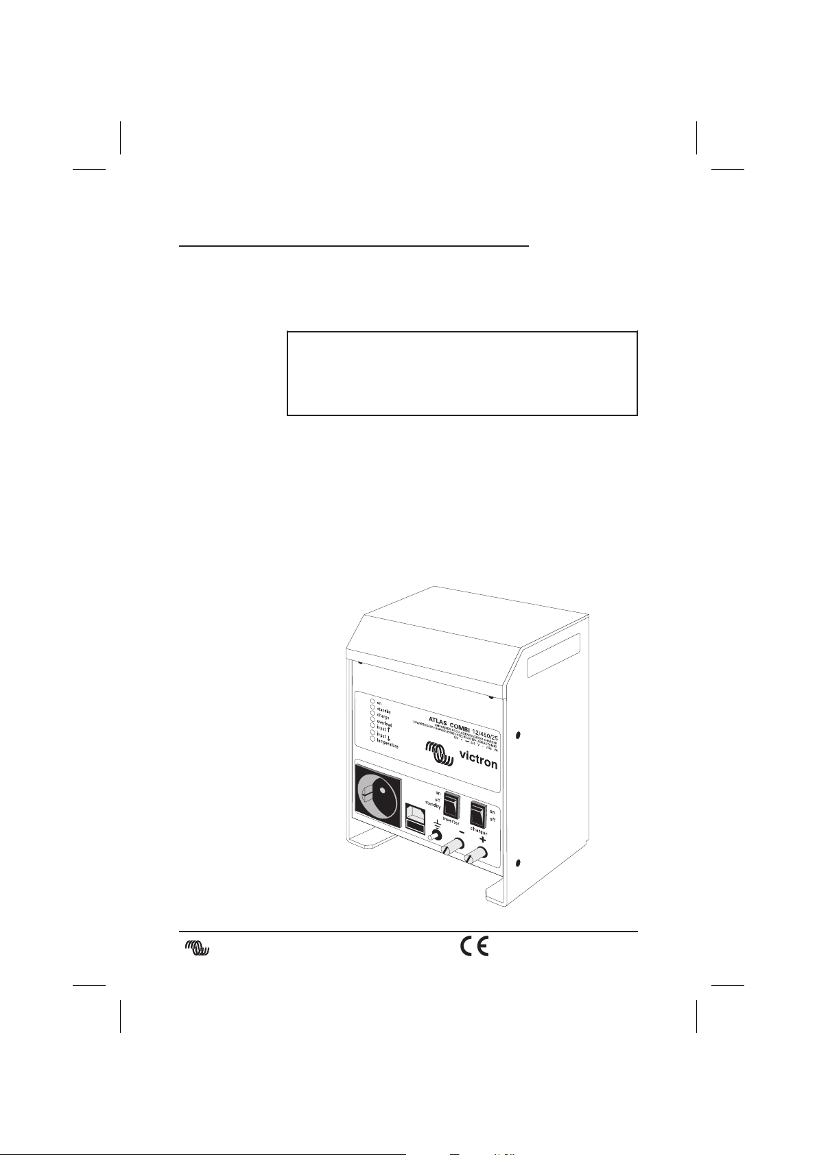
Victron Atlas Combi 12/450
This manual contains directions for installing the Atlas Combi
model 12/450. It describes the functionality and operation of
the Atlas Combi, including its protective devices and other
technical features.
victron energie
user manual 7