Victron energy Lynx Smart BMS 500 User manual

Lynx Smart BMS
ENGLISH

Table of Contents
1. Introduction ........................................................................................................................... 1
1.1. The Lynx Smart BMS ....................................................................................................... 1
2. Features ................................................................................................................................ 2
2.1. Batterie Management System ............................................................................................. 2
2.2. Contactor ..................................................................................................................... 2
2.3. Built-in pre-charge circuit ................................................................................................... 2
2.4. Battery Monitor .............................................................................................................. 2
2.5. Programmable relay ......................................................................................................... 2
2.6. AUX terminal ................................................................................................................. 2
3. Communication and interfacing ................................................................................................... 3
4. System Design considerations and examples .................................................................................. 4
4.1. Integration into the Lynx Distributor System .............................................................................. 4
4.2. System sizing ................................................................................................................ 5
4.2.1. Current rating Lynx Smart BMS ................................................................................. 5
4.2.2. Fusing .............................................................................................................. 5
4.2.3. Cabling ............................................................................................................. 5
5. Installation ............................................................................................................................. 6
5.1. Safety Precautions .......................................................................................................... 6
5.1.1. Safety Warnings Lynx Distribution System ..................................................................... 6
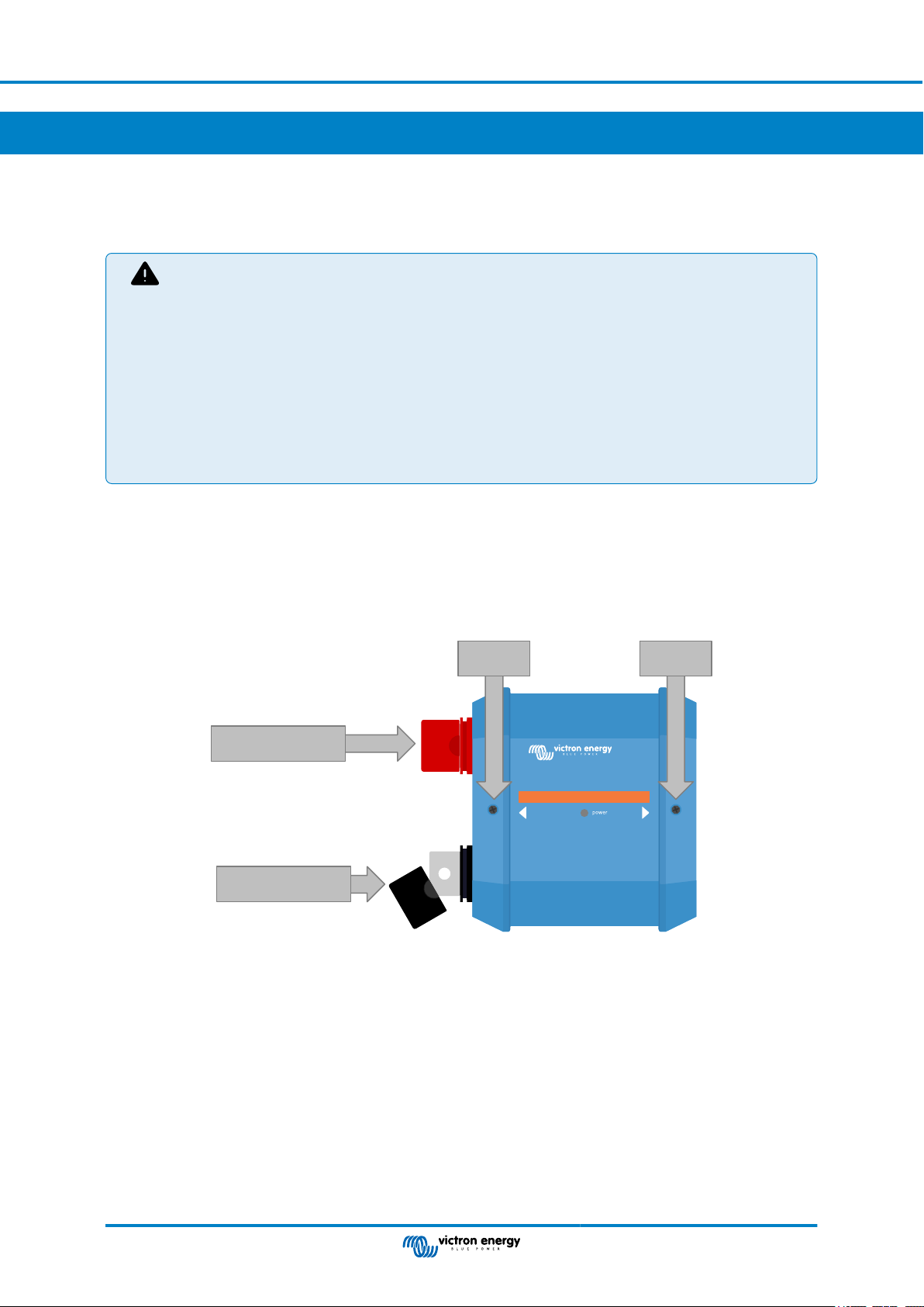
5.2. Mechanical connections .................................................................................................... 6
5.2.1. Lynx Smart BMS connection features .......................................................................... 6
5.2.2. Mounting and interconnecting Lynx modules .................................................................. 7
5.3. Electrical connections ....................................................................................................... 7
5.3.1. Connect DC wires ................................................................................................. 7
5.3.2. Connect RJ10 cable(s) ........................................................................................... 8
5.3.3. Connect BMS cables ............................................................................................. 8
5.3.4. Connect the Multi connector ..................................................................................... 9
5.3.5. Connect ATC/ATC controlled loads and chargers ............................................................. 9
5.3.6. Wiring a Remote on/off switch ................................................................................. 10
5.3.7. Programmable relay wiring ..................................................................................... 10
5.3.8. Connect the GX device ......................................................................................... 11
5.4. System examples in detail ................................................................................................ 11
5.4.1. Lynx Smart BMS, 2x Lynx Distributor and lithium batteries ................................................ 11
5.4.2. Lynx Smart BMS, 1x Lynx Distributor and lithium batteries ................................................ 12
5.4.3. Lynx Smart BMS only ........................................................................................... 13
6. Configuration and settings ....................................................................................................... 14
6.1. Power up for the first time ................................................................................................ 14
6.2. Update firmware ........................................................................................................... 14
6.3. Lynx Smart BMS settings ................................................................................................. 14
6.4. Lynx Distributor settings .................................................................................................. 16
7. Commissioning and Operation of the Lynx Smart BMS .................................................................... 18
7.1. Commissioning the Lynx Smart BMS ................................................................................... 18
7.2. Powering up ................................................................................................................ 18
7.3. BMS operating modes .................................................................................................... 20
7.4. Lynx Smart BMS trigger .................................................................................................. 21
7.5. Battery monitor operation ................................................................................................. 21
7.6. Battery care ................................................................................................................ 21
7.7. VictronConnect-Remote (VC-R) support* .............................................................................. 22
7.8. VictronConnect Bluetooth live data advertisement support* .......................................................... 22
8. Troubleshooting and Support ................................................................................................... 23
8.1. How to recover from OFF mode when no charge voltage was detected ............................................ 23
8.2. Lynx Smart BMS does not power up .................................................................................... 23
8.3. Lynx Smart BMS operational issues .................................................................................... 24
Lynx Smart BMS

8.4. BMS issues ................................................................................................................ 25
8.4.1. The BMS frequently disables the battery charger ........................................................... 25
8.4.2. The BMS is prematurely turning loads off .................................................................... 25
8.4.3. The pre-alarm setting is missing in VictronConnect ......................................................... 25
8.4.4. BMS is displaying alarm while all cell voltages are within range ........................................... 25
8.4.5. How to test if the BMS is functional ........................................................................... 26
8.4.6. System in OFF mode ........................................................................................... 26
8.4.7. ATC/ATD is missing ............................................................................................. 27
8.5. Battery monitor issues .................................................................................................... 27
8.5.1. Incomplete current reading ..................................................................................... 27
8.5.2. Incorrect state of charge reading .............................................................................. 27
8.5.3. State of charge does not increase/decrease fast enough or too fast when charging/discharging. .... 27
8.5.4. Synchronisation issues ......................................................................................... 27
8.6. VictronConnect issues .................................................................................................... 28
8.7. GX device issues .......................................................................................................... 28
9. Warranty ............................................................................................................................. 29
10. Technical specifications ......................................................................................................... 30
11. Appendix ........................................................................................................................... 31
11.1. LED indications, warnings, alarm and error codes ................................................................... 31
11.2. Supported NMEA 2000 PGNs .......................................................................................... 34
11.3. List of battery monitor settings .......................................................................................... 34
11.4. Multi connector pin-out and overview .................................................................................. 35
11.5. Lynx Smart BMS related menu structure of the GX device .......................................................... 35
11.6. Enclosure dimensions ................................................................................................... 37
Lynx Smart BMS

1. Introduction
1.1. The Lynx Smart BMS
The Lynx Smart BMS is a dedicated Battery Management System for Victron Lithium Smart Batteries. There are multiple BMS-es
available for our Smart Lithium series of batteries, and the Lynx Smart BMS is the most feature rich and complete option. Its main
features are:
• Built-in 500A contactor used as a fallback safety mechanism and also suitable as a remote controllable main system switch.
• Battery monitor, indicating state of charge percentage and more data.
• Pre-alarm signal: provide a warning before the system shuts down due to a low cell voltage.
• Bluetooth for use with our VictronConnect App, for setup, monitoring and diagnostic.
• Local and remote monitoring using a Victron GX device, for example the Cerbo GX and our VRM portal.
The Lynx Smart BMS integrates seamlessly into our Lynx Distributor system.
Lynx Smart BMS
Lynx Smart BMS
Page 1 Introduction

2. Features
2.1. Batterie Management System
The BMS is used to monitor, control and protect your Victron Lithium Batteries Smart. It detects the state of charge and protects
against deep discharge and overcharging.
It's main features are:
•Pre-alarm mode configurable via the programmable relay
•ATC/ATD ports to control chargers and loads
•DVCC support for compatible Victron inverter/charger and MPPTs via a connected GX device
•Discharge floor used to set the minimum SoC to determine how far the battery is allowed to be discharged. (requires
VictronConnect v5.70 or later)
A configurable pre-alarm warns with a minimum delay of 30 seconds of an imminent shutdown of the loads as a result of an
impending low cell voltage. By reacting quickly on the pre-alarm, for example by reducing the load or starting a generator to
charge the batteries, the shutting down of the loads can be prevented.
The ATC contact is opened to stop charging at high cell voltage or low temperature, while the ATD contact is opened to stop
discharging at a low cell voltage.
DVCC controls compatible devices via Lynx Smart BMS and a connected GX device. Charging current and voltages are set
automatically, thus Bulk, Absorption and Float algorithms are no longer used. Charging or discharging are stopped at low or high
cell voltage or low temperature.
2.2. Contactor
The built-in contactor serves two purposes:
1. It acts as a secondary safety system to protect the battery in case the primary controls (ATC and ATD contacts as well as
DVCC) fail to disable the loads and/or chargers when required.
2. It can be used as a remote controlled main system on/off switch via the VictronConnect app, a GX device (only Standby and
On), as well as using the Remote on/off terminals.
2.3. Built-in pre-charge circuit
The built-in pre-charge circuit pre-charges capacitive loads such as inverters or inverter/chargers before the contactor closes to
prevent high inrush current.
2.4. Battery Monitor
The Lynx Smart BMS battery monitor operates in a similar fashion as the other Victron Energy battery monitors. It contains a
shunt and battery monitor electronics. Readout of the battery monitor data is via Bluetooth using the VictronConnect App or a GX
device and the VRM portal.
2.5. Programmable relay
The Lynx Smart BMS has a programmable relay that can be used as an alarm relay (combined with the pre-alarm) or to shut
down an alternator via its external regulator (ignition wire).
2.6. AUX terminal
The Lynx Smart BMS is equipped with an auxiliary power supply. This supply outputs the same voltage as the system battery
voltage and is rated at a maximum continuous current rating of 1.1A.
The purpose of the auxiliary power supply is to keep certain systems powered, for example a GX device, after the BMS has
turned off loads in case of a low cell voltage event.
It is recommended that the system includes a GX device powered by the AUX port. This keeps the GX device
supplied with power until the AUX port is finally switched off (max. 2 hours after a low cell voltage event) to
preserve energy.
Lynx Smart BMS
Page 2 Features

3. Communication and interfacing
The Lynx Smart BMS communicates with other devices and services via a variety of interfaces. The following list provides an
overview of the most important interfaces:
•Bluetooth: to change settings and monitor the Lynx Smart BMS via our VictronConnect App.
Note that Bluetooth can be disabled via VictronConnect or a GX device, but can only be re-enabled from a GX device.
•VE.Can: to connect a GX device to the Lynx Smart BMS. The GX device will show all measured parameters, operational state,
battery SoC and alarms and make them available to be controlled via our remote monitoring VRM portal.
•Lynx Distributor fuse monitoring: via our VictronConnect app and a connected GX device. Communication with the Lynx
Distributors is via it's RJ10 connectors. The Lynx Smart BMS can be used to read out the Lynx Distributors, generate alarms in
case a fuse is blown or communication is lost. Fuse status communication requires Lynx Distributor with serial number HQ1909
or later.
•NMEA 2000 via VE.Can: Communication to an NMEA 2000 network can be established via VE.Can using a VE.Can to
NMEA2000 micro-C cable. See the Appendix for supported PGNs [34].
Lynx Smart BMS
Page 3 Communication and interfacing

4. System Design considerations and examples
4.1. Integration into the Lynx Distributor System
The Lynx Smart BMS integrates seamlessly with the Lynx Distributor system, which is not mandatory for operation, but highly
recommended due to its ease of installation.
It is important to note that the battery must always be connected to the left side of the Lynx Smart BMS (in normal position), while
all loads and chargers are connected to the right side.
The example below shows the Lynx Smart BMS in a system with two Lynx Distributors. Together they form a continuous busbar
with fused battery connections, battery monitor, BMS system, contactor and fused load connections.
The Lynx modules can be mounted in any orientation. Should they be mounted upside down, so that the text on the front of the
units is upside down as well, use the special stickers are included with each Lynx module, so that the text is orientated the correct
way.
Fused battery connections Fused DC loads and charge connectionsBattery monitor, BMS and contactor
Lynx Smart BMS with two Lynx Distributors
From battery bank
To DC system,
All DC loads and DC charge
sources
Example of Lynx module orientation: the batteries connect to the left and all loads and chargers connect on the right side
From battery bank
To DC system,
All DC loads and DC charge
sources
Example of Lynx modules mounted upside down: now the batteries connect to the right side, all loads and chargers connect to
the left side and the upside down stickers (included) are affixed.
It is important to note that the battery is always connected to the left side of the Lynx Smart BMS (in normal
position), while all loads and chargers go to the right side.
Lynx Smart BMS
Page 4
System Design considerations and
examples

4.2. System sizing
4.2.1. Current rating Lynx Smart BMS
The main safety contactor of the Lynx Smart BMS has a continuous current rating of 500A and a peak current rating of 600A
for a duration of 5 minutes. Even if the Lynx Smart BMS has an overcurrent protection, make sure that the current rating is not
exceeded.
The following happens in the event that the peak current limit or the 5 minute interval has been exceeded:
• an overcurrent alarm will be generated
• ATC or ATD (depending on current direction) is disabled after a 30s delay
It is not possible to parallel multiple Lynx Smart BMS modules. Only a single Lynx Smart BMS can be used per system.
The table below gives an idea of how much power a Lynx Smart BMS is rated for at different voltages. This will give you an
indication how big the connected inverter/charger system can be. Keep in mind that if inverters or inverter/chargers are used, both
the AC and the DC system will be powered from the batteries.
Voltage vs. Current 12V 24V 48V
500A 6kW 12kW 24kW
4.2.2. Fusing
The Lynx Smart BMS is not a system fuse. It only warns when the current is too high. Fusing needs to be done externally, for
example by connecting Lynx Distributor modules to the Lynx Smart BMS or by using external fuse holders and fuses.
Always use fuses with the correct voltage and current rating. Match the fuse rating to the maximum voltages and currents that
potentially can occur in the fused circuit. For more information on fuse ratings and fuse current calculations see the Wiring
Unlimited book.
The total value of the fuses of all circuits should not be more than the current rating of the Lynx module, or the
Lynx model with the lowest current rating in case of multiple Lynx modules are used.
4.2.3. Cabling
The current rating of the wires or cables used to connect the Lynx Smart BMS to batteries and/or the DC loads, has to be rated
for the maximum currents that can occur in the connected circuits. Use cabling with a sufficient core surface area to match the
maximum current rating of the circuit.
For more information on cabling and cable thickness calculations see our book, Wiring Unlimited.
Lynx Smart BMS
Page 5
System Design considerations and
examples

5. Installation
5.1. Safety Precautions
5.1.1. Safety Warnings Lynx Distribution System
• Installation must strictly follow the national safety regulations in compliance with the enclosure, installation,
creepage, clearance, casualty, markings and segregation requirements of the end-use application.
• Installation must be performed by qualified and trained installers only.
• Do not work on live busbars. Ensure that the busbar is unpowered by disconnecting all positive battery
poles prior to removing the Lynx front cover.
• Work on batteries should be carried out by qualified personnel only. Observe the battery safety warnings as
listed in the battery manual.
• Store this product in a dry environment. The storage temperature should be -40°C to +65°C.
• No liability can be accepted for damage in transit, if the equipment is not transported in its original
packaging.
5.2. Mechanical connections
5.2.1. Lynx Smart BMS connection features
• The Lynx Smart BMS cover can be opened up by unscrewing the two cover screws.
• Removable rubber sleeves to protect the busbar ends.
Cover
screw
Cover
screw
Removable sleeve
Positive busbar
Removable sleeve
Negative busbar
Location of front cover screws and the removable sleeves
Lynx Smart BMS
Page 6 Installation

5.2.2. Mounting and interconnecting Lynx modules
This paragraph explains how to attach several Lynx modules to each other and how to mount the Lynx assembly into its final
location. These are the points to take into consideration when interconnecting and mounting Lynx modules:
• If Lynx modules are going to be connected to the right and if the Lynx module is fitted with a plastic barrier on the right side,
remove the black plastic barrier. If the Lynx module is located as the most right module, leave the black plastic barrier in place.
• If Lynx modules are going to be connected to the left, remove the red and black rubber sleeves. If the Lynx module is located as
the most left module, leave the red and black rubber sleeves in place.
• Remember that for a Lynx Smart BMS, the left side is the battery side and the right side is the DC system side.
• Connect all Lynx modules to each other using the M8 holes and bolts on the left and right. Take care that the modules correctly
slot into the rubber joiner recesses.
• Place the washer, spring washer and nut on the bolts in the correct order and tighten the bolts to a torque of 14Nm.
• Mount the Lynx assembly in its final location using the 5mm mounting holes.
Lynx module
M8 bolt
M8 Spring washer
M8 Washer
Lynx module
Connection sequence when connecting two Lynx modules
5.3. Electrical connections
5.3.1. Connect DC wires
For all DC connections the following applies:
• All cables and wires connected to the Lynx module need to have been fitted with M8 cable lugs.
• Pay attention to the correct placement and order of the cable lug, washer, spring washer and nut on each bolt when attaching
the cable to the bolt.
• Tighten the nuts with a torque of 14Nm.
M8 bolt
M8 Spring washer
M8 Washer
Cable lug
Lynx module
Correct placement of the M8 Cable lug, washer, spring washer and nut
Lynx Smart BMS
Page 7 Installation

5.3.2. Connect RJ10 cable(s)
These instructions only apply, if the system contains Lynx Distributor(s).
There are two RJ10 connectors in each Lynx module, one on the left and one on the right. See below drawing.
RJ10 connector
RJ10 connector
RJ10 connector
Recess
RJ10 connector
Recess
RJ10 connector RJ10 connector
Recess Recess
Locations of the RJ10 connectors and RJ10 cable recesses on the Lynx Distributor, Lynx Smart BMS and the Lynx VE.Can
To connect the RJ10 cables between the Lynx Smart BMS and Lynx Distributor, do the following:
• Plug one side of the RJ10 cable in the RJ10 connector of the Lynx Distributor, with the retainer clip of the RJ10 connector
facing away from you.
• Feed the RJ10 cable through the recess at the bottom of the Lynx Distributor, see above picture.
• Plug the RJ10 cable into the RJ10 connector at the bottom of the Lynx Smart BMS.
Connection example Lynx Smart BMS system - RJ10 cables indicated in yellow
5.3.3. Connect BMS cables
Connect the BMS cables from the lithium battery to the BMS connectors on the Lynx Smart BMS.
BMS connectors
Location of the BMS cable connectors
In case multiple batteries (up to 26 batteries can be connected to the BMS) are used, first interconnect the battery BMS cables
and then connect the BMS cable from the first and last battery to the BMS connectors on the Lynx Smart BMS.
If the BMS cables are too short, use BMS extension cables.
Lynx Smart BMS
Page 8 Installation

Lynx Smart BMS battery BMS cable connection examples
5.3.4. Connect the Multi connector
The multi connector is the green connector on the bottom of the Lynx Smart BMS. The connector has 11 pins, numbered from left
to right starting with pin 1 and ending with pin 11.
See the Appendix for a table with pin-out and description [35].
The multi connector’s screw terminal can be pulled out of the Lynx Smart BMS, allowing for easy wiring.
The Remote on/off (pin 10 and 11) of the terminal are interconnected with a wire loop by default. If the Remote on/off connection
is used with a simple on/off switch, remove the loop and wire as desired.
1 2 3 4 5 6 7 8 9 10 11
Multi connector
Multi connector location
5.3.5. Connect ATC/ATC controlled loads and chargers
The ATC (allow-to-charge) and ATD (allow-to-discharge) are potential free dry contacts of the multi connector that can control
chargers and loads in the system, provided they have a remote on/off connector and are wired appropriately. They can be used in
several ways.
A common example is by providing +12V wired from AUX + (equal to system voltage) to pin 3 and pin 5. An active high signal
is then delivered to the connected remote H ports of the chargers and loads via pin 4 respectively pin 6. In case of a low cell
voltage, ATD opens the contact between pin 5 and pin 6. The load is then switched off and further discharge is prevented. If the
temperature is too low to charge, the ATC contact between pin 3 and pin 4 opens and switches off the chargers.
Instead of using system voltage on AUX +, system minus can be used on AUX - to generate an active L signal. The functionality
is the same as described above, except that the low signal ensures that the loads and chargers are switched off. This active L
signal then can be connected to the remote L terminals of a charger or load. In contrast to the H signal, System minus is also
present in case the contactor opens and the Lynx Smart BMS goes into OFF mode.
Another option is to use the ATC and ATD contacts as remote switches, for example to control a Smart BatteryProtect to turn off
loads in the event of low cell voltage or a charger in the event of low temperature.
See below examples for wiring:
Lynx Smart BMS
Page 9 Installation

For the system to operate correctly, it is essential that all loads and chargers are able to be controlled by
either DVCC or the ATC and ATD signals. Ideally wire the ATC and ATD signals to a devices remote on/off
connector, or, if that is not available, a Smart BatteryProtect or Cyrix-Li can be used.
5.3.6. Wiring a Remote on/off switch
Instead of the pre-installed wire loop between pin 10 and pin 11, a simple on/off switch can be wired to remotely turn the Lynx
Smart BMS on and off.
See below example for correct wiring:
Remote on/off
Simple Remote on/off switch wired between pin 10 and pin 11
For the Lynx Smart BMS to operate, the contact between pin 10 and pin 11 must be closed.
5.3.7. Programmable relay wiring
The programmable relay is an SPDT relay (Single Pole, Double Throw) with 3 contacts:
• Common (COM)
• Normally Open (NO)
• Normally Closed (NC)
The relay makes contact between COM and NC when the relay is not active, while COM and NO makes contact when the relay is
activated.
Depending on the Relay mode setting (Alarm relay or Alternator ATC) in the VictronConnect app, an audible (buzzer or external
speaker) or visible device (LED signal) or the signal line (usually the ignition wire) for the ATC signal of an external alternator
regulator can be connected.
Pin 8 COM PIN 9 NO
Pin 7 NC
Programmable relay not active
Pinout for the programmable relay
Lynx Smart BMS
Page 10 Installation

5.3.8. Connect the GX device
Connect the Lynx Smart BMS VE.Can port to the GX device VE.Can port using a RJ45 cable.
Multiple VE.Can devices can be daisy chained, but make sure that the first and the last VE.Can device both have a VE.Can RJ45
terminator installed.
Power the GX device from the AUX + and AUX – terminal of the Lynx Smart BMS.
RJ45 VE.can
connectors
Location of the VE.Can connectors on the Lynx Smart BMS
VE.Can RJ45
terminator
VE.Can RJ45
terminator
RJ45 UTP
cable
GX device
power cables
Wiring example Lynx Smart BMS and a CCGX
5.4. System examples in detail
5.4.1. Lynx Smart BMS, 2x Lynx Distributor and lithium batteries
A Lynx Smart BMS with two Lynx distributors and a Cerbo GX with GX touch panel form the heart of this system. They
continuously monitor the batteries, fuses, connected loads, chargers and inverter/charger(s).
A typical system can contain the following components:
• Lynx Smart BMS with built-in contactor and battery monitor.
• Lynx Distributor with 2 fused paralleled lithium batteries and identical cable lengths for each battery (up to 5 paralleled series
strings can be used per system).
• Lynx Distributor with fused connections for chargers, inverter/charger(s) and loads.
• A Cerbo GX (or other GX device).
Lynx Smart BMS
Page 11 Installation

ATD (allowed-to-discharge)
2 batteries in parallel
DC loads
Solar charger
RJ10 cable
BMS
cables
Lynx Distributor Lynx Smart BMS Lynx Distributor
RJ10 cable
BatteryProtect
Cerbo GX
VE.Bus
VE.Direct
GX touch 50 Inverter/charger
VE.Can
System with Lithium batteries, Lynx Smart BMS and two Lynx Distributors
5.4.2. Lynx Smart BMS, 1x Lynx Distributor and lithium batteries
The same as before, but this time with a single Lynx Distributor on the load side of the Lynx Smart BMS and the lithium battery
connected directly to the input of the Lynx Smart BMS. This is useful if only a single lithium battery or a single series string of
lithium batteries is used. Otherwise the same components are used.
DC loads
Solar charger
Cerbo GX
VE.Bus
VE.Direct
VE.Can
RJ10 cable
BMS cables
Lynx Smart BMS Lynx Distributor
Fuse
BatteryProtect
ATD (allowed-to-discharge)
GX touch 50
System with a Lynx Smart BMS and a single Lynx Distributor
Lynx Smart BMS
Page 12 Installation

5.4.3. Lynx Smart BMS only
For a very slim line system, the Lynx Smart BMS can be used just by itself. This is usefull if the system contains a single lithium
battery or a single series string of lithium batteries together with a simple DC system.
Please also note that no GX device is used. It is not absolutely necessary for the operation of the Lynx Smart BMS. However,
without GX device it is not possible to control compatible inverter/chargers and MPPTs via DVCC.
DC loads
BMS cables ATD (allowed to discharge)
Lynx Smart BMS
Fuse
System with a Lynx Smart BMS, without other Lynx modules and GX device.
Lynx Smart BMS
Page 13 Installation

6. Configuration and settings
6.1. Power up for the first time
The Lynx Smart BMS will power up when a battery is connected and the wire loop is placed in between pin 10 and 11 of the multi
connector or the Remote on/off switch is switched on.
On first power up and after a "Reset to defaults" (via VictronConnect app), the Lynx Smart BMS automatically determines and
sets these settings:
• System voltage, 12, 24 or 48V, by measuring the battery voltage.
• Pre-alarm support in the batteries.
The settings can also be reviewed and changed manually.
6.2. Update firmware
On a new install, it is recommended to update the firmware of the Lynx Smart BMS. If there is a newer firmware version available,
the VictronConnect app will notify you of this as soon as a connection with the Lynx Smart BMS is made.
To check if the firmware is up to date or to manually update firmware, connect to the Lynx Smart BMS using the VictronConnect
app and follow below steps:
1. Navigate to the product settings by clicking the cogwheel icon in the top right hand corner of the product status screen.
2. Click on the 3 dots icon in the top right hand corner of the settings screen.
3. Select "Product info" from the pop-up menu.
4. The firmware version will be displayed. It is mentioned whether this is the latest firmware version. If a newer firmware version
is available, an "UPDATE" button will appear.
5. To update the firmware, press the "UPDATE" button.
The firmware update is even easier via the VRM: Remote firmware update feature (requires a GX device in the system and
internet connection).
In case of a new installation, it is also recommended to check and update the firmware of each connected lithium battery. This is
done via Bluetooth using the VictronConnect app in a similar manner to that outlined above.
Updating the firmware always starts a new full charging cycle despite the SoC threshold setting, which means
that the charge voltage limit (CVL) is automatically adjusted from 13.5V to 14.2V (for a 12V system).
6.3. Lynx Smart BMS settings
Once powered up, use the VictronConnect app to configure the BMS settings.
Check the Battery voltage setting (12, 24 or 48V):
• This will have been detected automatically, double check it.
Set the Battery capacity setting:
• Enter the total battery bank capacity of the connected battery. Caution, for batteries connected in series, do not add the
capacity of each battery to determine the total capacity of the bank.
• Check out our book Wiring Unlimited section 3.1 to learn how to determine battery capacity.
If the battery capacity input is incorrect, the SoC will also be incorrectly calculated. Make sure the battery
capacity calculation is correct.
Set the Number of batteries in parallel :
• Enter the number of paralleled batteries in the system.
The wrong number of parallel batteries will lead to a miscalculation of the balancing algorithm. Make sure this
value is entered correctly.
Check the Pre-alarm mode setting:
Lynx Smart BMS
Page 14 Configuration and settings

This setting is automatically configured upon initial power-up and after a "Reset to defaults". It is enabled by default.
• enabled: recommended setting. A visual or audible device linked to the programmable relay is activated in case of a pre-alarm.
• disabled: If disabled, it will ignore the discharge current limit at pre-alarm setting.
Older Victron Lithium Batteries Smart manufactured before 2019/2020 do not have the pre-alarm signal.
Nevertheless, the Lynx Smart BMS also generates the pre-alarm signal for these batteries with the restriction
that the threshold for this is derived from the undervoltage alarm setting (in the battery) of 2.6V - 2.8V. The
undervoltage alarm then occurs with a fixed delay of 30 seconds after pre-alarm.
Set the Relay setting:
The programmable relay has two operation modes: Alarm relay and Alternator ATC.
• When set to Alarm relay mode, the Alarm relay setting becomes active and continuous or intermittent operation can be
selected. In intermittent operation the relay switches on and off every 0.8 seconds.
• When configured for Alternator ATC mode, the relay will only activate when the contactor is closed. Before the contactor
is opened, Alternator ATC is opened first and 2 seconds later the contactor. These 2 seconds ensure that the alternator is
switched off before the battery is disconnected from the system.
DVCC settings:
DVCC is forced on and cannot be turned off. However, a few settings can be changed, which are described below.
Please note that these settings only affect compatible DVCC devices such as Victron inverter/chargers and Solar MPPT chargers.
•Discharge Current Limit at pre-alarm (default "No"): if set to "Yes", the discharge current limit is already set to 0A in the event
of a pre-alarm, while the ATC contact remains closed. In this way it’s possible to save some battery power for essential DC
loads, for example on boats such as lighting, bilge pump and navigation.
•Absorption time: is set to 2 hours by default. This can be adjusted if necessary.
•Repeated absorption interval: in days at which a new full charging cycle is started, if the battery SoC does not fall below the
SoC threshold. The default is every 30 days and can be adjusted if required.
•SoC threshold: is set by default to 70%. This is the threshold at which the Lynx Smart BMS starts a new full charging cycle.
This can be adjusted if required.
A new charge cycle means that the CVL (charge voltage limit) is increased from 13.5V (for a 12V battery) to 14.2V.
In addition to the SoC threshold, a new charging cycle is started after a firmware update, when the battery voltages are below
12V/24V/48V (3V per cell) or when a low cell voltage is detected.
Battery monitor settings:
Unlike other battery monitors, the Lynx Smart BMS battery monitor settings are mostly fixed settings and are not customisable.
The reason for this is that the Lynx Smart BMS is always used together with Victron Lithium Batteries Smart and a lot of battery
monitor parameters are therefore known because they relate to the battery type.
The following settings are adjustable. A full list of all settings used can be found in the Appendix section 10.3. [34]
•Charged voltage: the voltage at above which the battery monitor synchronises and resets the SoC to 100%. For
synchronisation to happen, the tail current and charged detection time conditions need to have been met as well. The default
is set to 14.0V and can be adjusted if necessary. In case the system voltage setting is changed, the charged voltage setting
needs to be adjusted as well.
•Tail current: the current at below which the battery monitor synchronises and resets the SoC to 100%. For synchronisation to
happen, the charged voltage and charge detection time conditions need to have been met as well. The default is set to 4% and
can be adjusted if needed.
•Charged detection time: is the time passed after which the battery monitor synchronises and resets the SoC to 100%. For
synchronisation to happen, the charged voltage and tail current conditions need to have been met as well. The default is set to
3 minutes and can be adjusted if necessary.
•Discharge floor:* this parameter has two functions:
• Its primary use is to set the minimum SoC to determine how far you want to discharge the battery.
A limited depth of discharge is good for battery health, but also provides backup power to keep the system running, e.g. until
sunrise for solar systems.
Loads are disabled via ATD or DVCC when the set discharge level is reached, but the contactor remains closed, AUX
remains ON and the ATC contact remains closed as well to allow recharging the battery. At the same time, a Low SoC alarm
is issued.
Setting the discharge floor to zero (not recommended), disables this feature.
Lynx Smart BMS
Page 15 Configuration and settings

The discharge floor prevents full discharge and should be chosen so that there is enough energy to keep
the Lynx Smart BMS powered for 24 hours to provide sufficient time to recharge the battery.
If the battery is not recharged after the discharge floor has been reached, the battery will continue to be
discharged through self consumption until a low cell voltage event occurs, at which point the Lynx Smart
BMS will go into OFF mode with a delay of 2 hours to prevent deep discharge.
• It is used in the calculation for the 'Time remaining' or 'Time-to-go' value displayed in the VictronConnect app, a connected
GX device or on the VRM portal. The battery monitor uses the actual discharge current to calculate the time it takes to reach
the set discharge floor.
•Low SoC warning level:* the level at which a warning is issued before the discharge floor has been reached.
•State of charge:* manually set the current state of charge.
•Synchronise SoC to 100%:* manually synchronise SoC to 100%.
* requires VictronConnect v5.70 or later and Venus OS v2.90 or later
VictronConnect settings Lynx Smart BMS
6.4. Lynx Distributor settings
These instructions only apply if the system contains one or more Lynx Distributors.
Each Lynx distributor must be addressed and set to A, B, C or D. This is done via a 2-way dip switch located inside the Lynx
Distributor. Refer to chapter 6.1.3. Addressing Lynx Distributor in the Lynx distributor manual.
Use the VictronConnect app to give each fuse a custom name (maximum 16 characters). If the fuse name is empty (0
characters), the fuse will be disabled and ignored for monitoring.
1. Navigate to the Settings page by clicking the cog wheel icon at the top right hand corner.
2. On the Settings page scroll down to the Lynx Distributor settings.
3. Tap on a distributor name. A new menu opens with all 4 fuses.
4. Tap on a fuse to assign a custom name and/or to disable the fuse manually from monitoring.
Lynx Smart BMS
Page 16 Configuration and settings

Lynx Smart BMS
Page 17 Configuration and settings
Table of contents
Other Victron energy Camera Accessories manuals

Victron energy
Victron energy Smart Battery Sense User manual

Victron energy
Victron energy Pylontech UP2500 User manual

Victron energy
Victron energy LiFePO4 Battery 12,8V/60Ah Smart User manual

Victron energy
Victron energy Smart BatteryProtect User manual

Victron energy
Victron energy Lynx Ion + Shunt 350 User manual

Victron energy
Victron energy Pylontech US2000 User manual

Victron energy
Victron energy OPzS User manual

Victron energy
Victron energy BSLBATT User manual

Victron energy
Victron energy Lynx Ion User manual