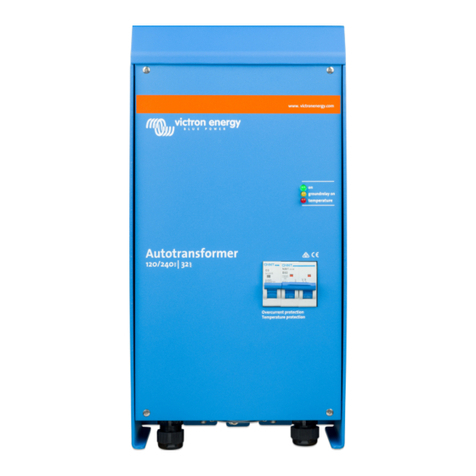
Victron energy 2000W User manual

Table of Contents
1. Safety Instructions ................................................................................................................... 1
2. Features ................................................................................................................................ 2
2.1. Electrical safety .............................................................................................................. 2
2.2. Galvanic corrosion prevention ............................................................................................. 2
2.3. Converting voltages ......................................................................................................... 3
2.4. Soft start ...................................................................................................................... 3
2.5. Internal wiring diagram ...................................................................................................... 3
2.6. Safety when the vessel is out of the water ............................................................................... 4
3. Installation ............................................................................................................................. 5
3.1. What's in the box ............................................................................................................ 5
3.2. Connections overview ...................................................................................................... 5
3.3. AC Input configuration ...................................................................................................... 6
3.4. AC output configuration ..................................................................................................... 6
3.5. Connecting AC input and AC output ...................................................................................... 7
3.6. AC output neutral to earth link ............................................................................................. 8
3.7. Cable cross-section requirements ......................................................................................... 8
3.8. Wiring example .............................................................................................................. 9
3.9. Linking input and output earth when the vessel is out of the water. ................................................... 9
4. Operation ............................................................................................................................ 10
4.1. Inrush current limiter ...................................................................................................... 10
4.2. Temperature protection ................................................................................................... 10
5. Technical specifications .......................................................................................................... 11
6. Dimensions .......................................................................................................................... 12
Isolation Transformer

1. Safety Instructions
WARNING: Before installing, using, storing or transporting this product, read and save the safety instructions
below.
General:
• Review the related documentation of this product to familiarise yourself with safety markings and
instructions before operating the equipment. This product has been designed and tested in accordance with
international standards. Only use the equipment for the intended purpose of application and in accordance
with the specifications as stated in the Technical specification chapter.
• WARNING: RISK OF ELECTRIC SHOCK.
• Do not open the enclosure if the product is still connected to an electrical power source.
• Do not remove the front panel or operate the product without all panels fitted. Refer all servicing to qualified
personnel.
• Caution: never carry heavy loads without assistance.
• Do not expose the product to water, mist, snow, spray, or dust.
• Do not use the product in locations where there is a risk of gas or dust explosions. This product is not
ignition protected.
Installation:
• Always refer to the installation section in the manual before applying power to the equipment.
• Connections, cable sizes and safety features must be according to the locally applicable regulations.
• This is a safety class I product (provided with a protective earthing terminal). An uninterruptible safety
earth ground must be provided at the AC-in and AC-out terminals. An additional grounding point is located
at the outside of the product. Whenever it is likely that the grounding protection has been impaired, the
product must be made inoperative and secured against any unintended operation; refer to qualified service
personnel.
• Make sure that circuit breakers are provided in the connecting wires. Never replace a safety component
with a different type. Consult the manual to determine the correct component.
• Before applying power, verify that the available power source matches the configuration settings of the
product as described in the manual.
• Ensure that the environmental conditions are suitable for the operation of the equipment. Never operate
the product in the rain or a dusty environment. Allow at least 10cm of free space around the product for
ventilation, and ensure that ventilation fans are not blocked. Install in a well-ventilated and heat-resistant
environment. Avoid the presence of, e.g. chemicals, synthetic components, curtains or other textiles in the
immediate vicinity of the product.
• Be sure that the demanded power does not exceed the product's power rating.
Transport and storage:
• When storing or transporting the product, make sure that all mains power leads are disconnected.
• No liability can be accepted for any transport damage when equipment is shipped in non-original packaging.
• Store the product in a dry location. Storage temperature must be between -20°C and 60°C.
Isolation Transformer
Page 1 Safety Instructions

2. Features
The isolation transformer eliminates any electrical continuity between AC shore power and the vessel. It is essential for safety and
eliminates the need for galvanic isolators and polarity alarms.
2.1. Electrical safety
Electrical safety is taken for granted in the case of a standard on-shore installation. A circuit breaker will trip, or a GFCI (Ground
Fault Circuit Interrupter) will trip in case of a short circuit or a current leakage to ground. Connecting the ground wire of the
shore-side supply to a vessel's metal parts will result in galvanic corrosion.
Bringing only the live and neutral wire onboard results in an unsafe situation because GFCIs will not work, nor will a breaker trip in
case of a short circuit to a metal part on the vessel.
2.2. Galvanic corrosion prevention
Galvanic corrosion occurs when two dissimilar metals in electrical contact are simultaneously exposed to an electrically
conducting fluid. Seawater and, to a lesser extent, freshwater are such fluids. In general, the more active alloy of the couple
corrodes preferentially, while the less active (more noble) material is cathodically protected. The rate of galvanic corrosion is a
function of several variables, including area ratios, the conductivity of the fluid, temperature, the nature of the materials, etc.
It is a misunderstanding that galvanic corrosion occurs only in metal and aluminium hulls. In fact, it can occur on any vessel as
soon as a metallic part (the shaft and propeller) is in contact with water. Galvanic corrosion will quickly dissolve your sacrificial
anodes and attack the shaft, propeller and other metal parts in contact with water when the vessel is connected to the shore-side
supply. It might therefore be tempting not to connect the ground conductor: this is, however, extremely dangerous because a
GFCI will not work, nor will a circuit breaker trip in case of a short circuit to a metal part on the vessel.
The best solution to avoid galvanic corrosion and, at the same time, prevent any unsafe situation is to install an isolation
transformer to connect to the shore-side supply. The isolation transformer eliminates any electrical continuity between shore
power and the vessel. The shore power is fed to the transformer's primary side, and the vessel is connected to the secondary.
The isolation transformer completely isolates the vessel from the shore ground. By connecting all metal parts to the neutral output
on the secondary side of the transformer, a GFCI or a breaker will trip in case of a short circuit.
The shore ground connected to immersed metals of the vessel causes
galvanic corrosion.
ID Description
A Shore AC supply
B Shore AC distribution
C GFCI (ground fault circuit interrupter)
D Vessel AC supply
E Galvanic corrosion
Isolation Transformer
Page 2 Features

The shore ground is isolated from the vessel ground, and galvanic
corrosion originating from the shore connection is blocked.
ID Description
A Shore AC supply
B Shore AC distribution
C Isolation transformer
D GFCI (ground fault circuit interrupter)
E Vessel AC supply
2.3. Converting voltages
The isolation transformer converts the input voltage with a 1:1.05 ratio. The 1:1.05 transformer ratio boosts the output voltage of
the isolation transformer by 5%. This is to compensate for shore power voltage drops that are a common occurrence in marinas.
The isolation transformer can be used in 115V or 230V systems and also be used to convert 230V to 120V and 115V to 240V.
Depending on the isolation transformer configuration:
• A 230V input becomes 240V.
• A 230V input becomes 120V.
• A 115V input becomes 240V.
• A 115V input becomes 120V.
The isolation transformer can be used in 50Hz or 60Hz systems. However, the isolation transformer cannot convert frequencies
from 50Hz to 60Hz or vice versa.
2.4. Soft start
Soft start is a standard feature of a Victron Energy isolation transformer. It will prevent the shore power circuit breaker from
tripping due to the transformer inrush current.
2.5. Internal wiring diagram
Internal wiring diagram of the isolation transformer.
ID Description
A Shore AC connection
B Soft start
C Transformer
D Vessel AC connection
E Neutral - Earth link (removable)
F Shore Earth
G Vessel Earth
Isolation Transformer
Page 3 Features

2.6. Safety when the vessel is out of the water
It is recommended, for optimal safety, to connect the shore earth to the vessel's earth when the vessel is out of the water, in
winter or for maintenance. The isolation transformer has a facility for this.
Isolation Transformer
Page 4 Features

3. Installation
3.1. What's in the box
The isolation transformer ships with the following items:
Description
1x hanging bracket, used for mounting the isolation transformer inside a vessel.
1x isolation transformer.
1x long yellow/green jumper wire with female 6.35 mm spade connectors, used to connect AC input earth (PE) to AC output
earth (PE) when the vessel is out of the water for maintenance or winter storage.
1x long yellow/green wire with eye terminals, used for case grounding (not included for the 2000W model).
1x short yellow/green jumper wire with female 6.35 mm spade connectors, used to make AC output neutral (N) to earth (PE)
link.
4x short black jumper wires with 6.35 mm female spade connectors, used for AC configuration.
7x mounting screws for the 3600W model and 4x mounting screws for the 2000W model.
3.2. Connections overview
I
D
Description
1
Male spade terminals to configure the AC input voltage:
For 115V, connect J17 to J20 and connect J4 to J7.
For 230V, connect J4 to J20.
2
Male spade terminals to configure the AC output voltage:
For 115V, connect J29 to J32 and connect J31 to J25.
For 230V, connect J31 to J32.
3
Male spade terminals to establish an AC output neutral to earth connection link for a correct operation of an AC output
GFCI:
J33 and J21.
4AC input terminal (shore power) :
Phase (L) neutral (N) and earth (PE).
5Male spade terminals to bridge AC input earth to AC output earth when the vessel is out of the water:
J34A and J34.
6AC output terminal (AC loads or AC installation):
Phase (L) neutral (N) and earth (PE).
Isolation Transformer
Page 5 Installation

3.3. AC Input configuration
The AC input needs to be configured for 115 or 230V use. This is done by connecting male spade terminals using the black
jumper wires (included). These terminals are located above the AC input connector.
AC input
voltage
Connect
jumper cable
between
Connections
115V J17 and J20
J4 and J7
230V J4 and J20
3.4. AC output configuration
The AC output needs to be configured for 115 or 230V use. This is done by connecting male spade terminals using the black
jumper wires (included). These terminals are located above the AC output connector.
Isolation Transformer
Page 6 Installation

AC output
voltage
Connect
jumper cable
between
Connections
115V J29 and J32
J31 and J25
230V J31 and J32
3.5. Connecting AC input and AC output
Shock hazard. Do not work on the isolation transformer or the electrical system if still connected to an
electrical power source.
Connection sequence:
1. Pass the AC cables through the cable glands at the bottom of the cabinet in the following way:
a. Pass the AC input (shore power) cable through the left side cable gland.
b. Pass the AC output (AC loads) cable through the right side cable gland.
2. Connect the AC input cable to the INPUT terminal block in the following way:
a. Connect the earth wire to the PE terminal.
b. Connect the neutral wire to the N terminal.
Isolation Transformer
Page 7 Installation

c. Connect the phase wire to the L terminal.
3. Connect the AC output cable to the OUTPUT terminal block in the following way:
a. Connect the earth wire to the PE terminal.
b. Connect the neutral wire to the N terminal.
c. Connect the phase wire to the L terminal.
4. Connect the enclosure to the ground (=all the metal parts in the vessel) in the following way:
a. Connect the M6 bolt underneath the enclosure to the vessel ground. See the below drawing for the location of the chassis
earth bolt.
Location of the chassis earth bolt.
3.6. AC output neutral to earth link
A GFCI must be installed in the AC output of the isolation transformer. For the GFCI to operate correctly, the AC output neutral
must be connected to the AC output earth and ground (= all the metal parts in the vessel).
To link the AC output neutral (N) to earth (PE), place a green/yellow jumper wire (included) between the J33 and J21 male spade
connectors.
AC output neutral (N) to earth (PE) link.
3.7. Cable cross-section requirements
Use the following minimal cable cross-sections:
Isolation transformer power rating Voltage Metric AWG
2000W 115V 2.5mm² AWG 13
2000W 230V 1.5mm² AWG 16
3600W 115V 6mm² AWG 10
3600W 230V 2.5mm² AWG 13
Isolation Transformer
Page 8 Installation

3.8. Wiring example
Wiring example isolation transformer installed on a vessel connected to shore power.
I
D
Description
A Shore power.
B Circuit breaker.
C GFCI (Ground Fault Circuit Interrupter).
D Shore cable.
E Isolation transformer.
F AC loads.
3.9. Linking input and output earth when the vessel is out of the water.
For safety reasons, when the vessel is out of the water (on land) during winter or for maintenance, the vessel's earth (PE)
conductor must be connected directly to the shore power earth (PE) conductor.
This can be achieved inside the isolation transformer by connecting the yellow/green jumper wire (included) between male spade
terminals J34A and J34, as indicated below.
AC input earth is connected to AC output earth when the vessel is out of the water (on land) during winter or for maintenance.
Isolation Transformer
Page 9 Installation

4. Operation
Check the input and output voltage configuration before operating the isolation transformer.
4.1. Inrush current limiter
The inrush current limiter prevents upstream circuit breakers from tripping when switching on the isolation transformer.
4.2. Temperature protection
The isolation transformer is fan cooled. The fan speed is temperature-controlled. Its speed (rpm) will increase if the temperature
increases.
The isolation transformer is protected against overtemperature and will switch off in case of overheating.
Isolation Transformer
Page 10 Operation

5. Technical specifications
Isolation Transformer 2000 Watt 3600 Watt
AC input voltage * 115 or 230V 115 or 230V
AC output voltage * 120 or 240V 120 or 240V
Frequency 50/60Hz 50/60Hz
Output current rating 19A (115V)
8.5A (230V)
32A (115V)
16A (230V)
Soft start Yes
Operating temperature range -20°C to 40°C
Humidity Max 95%, non-condensing
Transformer type Toroidal (low noise, low weight), 1:1.05 ratio
Enclosure Aluminium (blue RAL 5012)
Protection category IP21
Safety EN 60076
Weight 12.7kg 23kg
Dimensions (h x w x d), mm 375 x 214 x 135 362 x 258 x 218
*) The isolation transformer can be used as:
• 115V to 120V isolation transformer
• 230V to 240V isolation transformer
• 115V to 240V isolation transformer
• 230V to 120V isolation transformer
Isolation Transformer
Page 11 Technical specifications

6. Dimensions
2000W model
214.5
375.6
135
100 30
17
12 30
6.4(3x)
125 10
281.2
286.2
75.25
100
6.5(2x)
Rev00
Dimensions in mm
Dimension Drawing - Isolation Transformer
ITR040202041
Isolation Transformer 2000W 115/230V
D
E
F
C
1
2
3
4
B
A
3
2
1
5
C
D
4
6
7
8
A
B
8
7
6
5
F
E
Isolation Transformer
Page 12 Dimensions

3600W model
Isolation Transformer
Page 13 Dimensions
This manual suits for next models
1
Table of contents
Other Victron energy Transformer manuals
Popular Transformer manuals by other brands

SSS Siedle
SSS Siedle TR 602-0 quick start guide

marklin
marklin 60061 manual

Charles
Charles Isotransformer 93-IXFMR3/6-A Installation instructions & owner's manual

GÜDE
GÜDE 69010 operating manual

AquaCal AutoPilot
AquaCal AutoPilot ST-100-12 installation guide

DX Engineering
DX Engineering Maxi-Core DXE-BAL050-Series manual