08/27/14 INS-24C1.3XW Rev A
Prior to Using This Document: Videology reserves the right to
modify the information in this document as necessary and without
notice. It is the user’s responsibility to be certain they possess the
most recent version of this document by going to www.videologyinc.
com, searching for the model number, and comparing revision let-
ters on the respective document, located in the document’s footer.
For technical assistance with this product, please contact the suppli-
er from whom the product was purchased.
License Agreement (Software):
This Agreement states the terms and conditions upon which Videol-
ogy Imaging Solutions, Inc. USA and Videology Imaging Solutions,
B.V. Europe (hereafter referred to as “Videology®”) offer to license
to you the software together with all related documentation and
accompanying items including, but not limited to, the executable
programs, drivers, libraries, and data files associated with such
software.
The Software is licensed, not sold, to you for use only under the
terms of this Agreement.
Videology grants to you, the purchaser, the right to use all or a
portion of this Software provided that the Software is used only in
conjunction with Videology’s family of products.
In using the Software you agree not to:
• Decompile, disassemble, reverse engineer, or otherwise
attempt to derive the source code for any Product (except to the
extent applicable laws specifically prohibit such restriction);
• Remove or obscure any trademark or copyright notices.
Limited Warranty (Hardware and Software):
ANY USE OF THE SOFTWARE OR HARDWARE IS AT YOUR OWN
RISK. THE SOFTWARE IS PROVIDED FOR USE ONLY WITH VIDE-
OLOGY’S HARDWARE. THE SOFTWARE IS PROVIDED FOR USE “AS
IS” WITHOUT WARRANTY OF ANY KIND, TO THE MAXIMUM EXTENT
PERMITTED BY LAW, VIDEOLOGY DISCLAIMS ALL WARRANTIES OF
ANY KIND, EITHER EXPRESS OR IMPLIED, INCLUDING, WITHOUT
LIMITATION, IMPLIED WARRANTIES OR CONDITIONS OF MER-
CHANTABILITY, QUALITY AND FITNESS FOR A PARTICULAR APPLI-
CATION OR PURPOSE. VIDEOLOGY IS NOT OBLIGATED TO PROVIDE
ANY UPDATES OR UPGRADES TO THE SOFTWARE OR ANY RELATED
HARDWARE.
Limited Liability (Hardware and Software):
In no event shall Videology or its Licensor’s be liable for any dam-
ages whatsoever (including, without limitation, incidental, direct,
indirect, special or consequential damages, damages for loss of
business profits, business interruption, loss of business information,
or other pecuniary loss) arising out of the use or inability to use this
Software or related Hardware, including, but not limited to, any of
Videology’s family of products.
1. Document History
Revision Issue Date Reason CN#
Rev A 08-27-14 Initial release Preliminary
The lightning flash with an arrowhead symbol, within an
equilateral triangle is intended to alert the user to the
presence of uninsulated dangerous voltage within the
product’s enclosure that may be of sufficient magnitude to
constitute a risk of electric shock to persons.
The exclamation point within an equilateral triangle is
intended to alert the user to the presence of important
operating and maintenance (servicing) instructions in the
literature accompanying the appliance.
INFORMATION - This equipment generates, uses, and can radiate
radio frequency energy and, if not installed and used in accordance
with the instruction manual, may cause harmful interference to
radio communications. As an OEM product, it is expected and rec-
ommended that the user will place this model into a proper housing.
Operation of this equipment in a residential area is likely to cause
harmful interference in which case the user will be required to cor-
rect the interference at his own expense.
WARNING: Changes or modifications not expressly approved by
the manufacturer could void the user’s authority to operate the
equipment.
CAUTION: To prevent electric shock and risk of fire hazards:
- Do NOT use power sources other than those specified.
- Do NOT expose this appliance to rain or moisture.
This installation should be made by a qualified service person and
should conform to all local codes.
2. Warning
•The camera requires periodic inspection.
Contact an authorized technician to carry out the inspection.
•Stop using your camera when you find it malfunctioning.
If the camera emits smoke or is unusually hot for a long period, a
fire may be caused.
•Do not install the camera on a surface that cannot support it.
If the camera is installed on an inappropriate surface, it may fall
and cause injury.
•Do not hold plug with wet hands.
It could cause an electric shock.
•Do not dis-assemble the camera.
It may result in an electric shock or other hazards.
•Do not use the camera close to a gas or oil leak.
It may result in a fire or other hazards.
OSD Instructions
24C1.3XW
WDR Analog 800TVL
Table of Contents
1. Document History 1
2. Warning 1
3. Precautions 2
4. Camera Operation 2
4.1 Menu 2
4.2 How to Setup the Functions 2
4.3 Focus Adj 2
4.4 Lens 2
4.5 Exposure 2
4.6 White Balance 3
4.7 Backlight 3
4.8 DNR 3
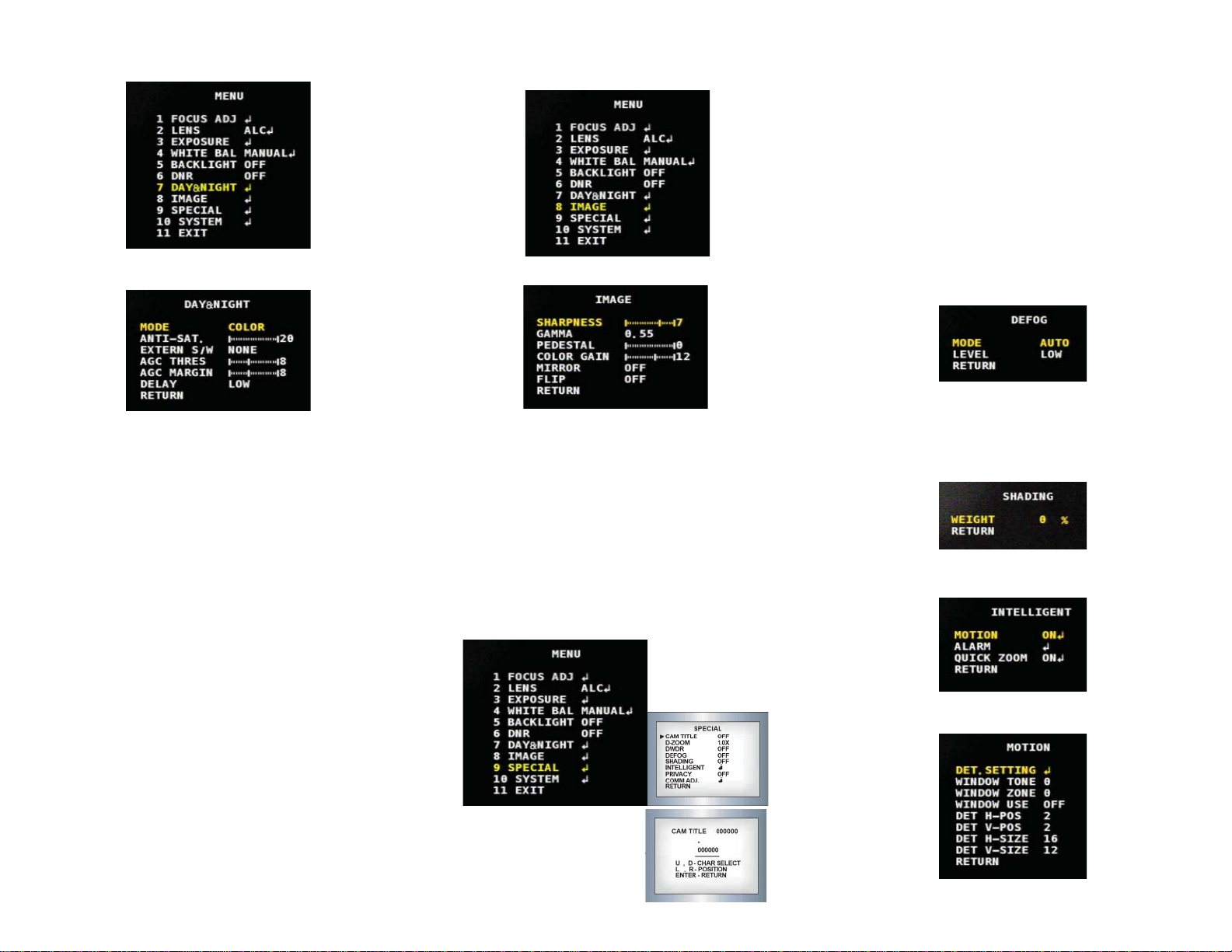
4.9 Day & Night 4
4.10 Image 4
4.11 Special 4
4.12 System 5
4.13 Exit 5
5. Troubleshooting 5
6. Specifications 6
7. Contact Information 6