Videotec PUNTO Hi-PoE User manual

ENGLISHITALIANOFRANÇAISDEUTSCH
EN English - Instructions manual
IT Italiano - Manuale di istruzioni
FR Français - Manuel d’instructions
DE Deutsch - Bedienungslanleitung
PUNTO Hi-PoE
Technopolymer housing for IP cameras


EN English - Instructions manual
ENGLISH
PUNTO Hi-PoE
Technopolymer housing for IP cameras

Contents ENGLISH
1 About this manual ......................................................................................................... 3
1.1 Typographical conventions.................................................................................................................................. 3
2 Notes on copyright and information on trademarks.................................................. 3
3 Safety rules..................................................................................................................... 3
4 Identication.................................................................................................................. 4
4.1 Product description and type designation..................................................................................................... 4
4.2 Product markings .................................................................................................................................................... 4
5 Preparing the product for use ...................................................................................... 5
5.1 Unpacking and contents....................................................................................................................................... 5
5.1.1 Unpacking.................................................................................................................................................................................. 5
5.1.2 Contents...................................................................................................................................................................................... 5
5.2 Safely disposing of packaging material........................................................................................................... 5
5.3 Preparatory work before installation................................................................................................................ 5
5.3.1 Attaching the support ........................................................................................................................................................... 5
6 Assembling and installing ............................................................................................ 5
6.1 Assembly..................................................................................................................................................................... 5
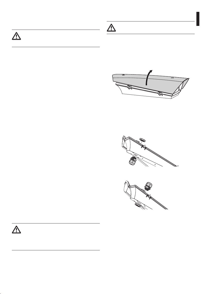
6.1.1 How to open the housing..................................................................................................................................................... 5
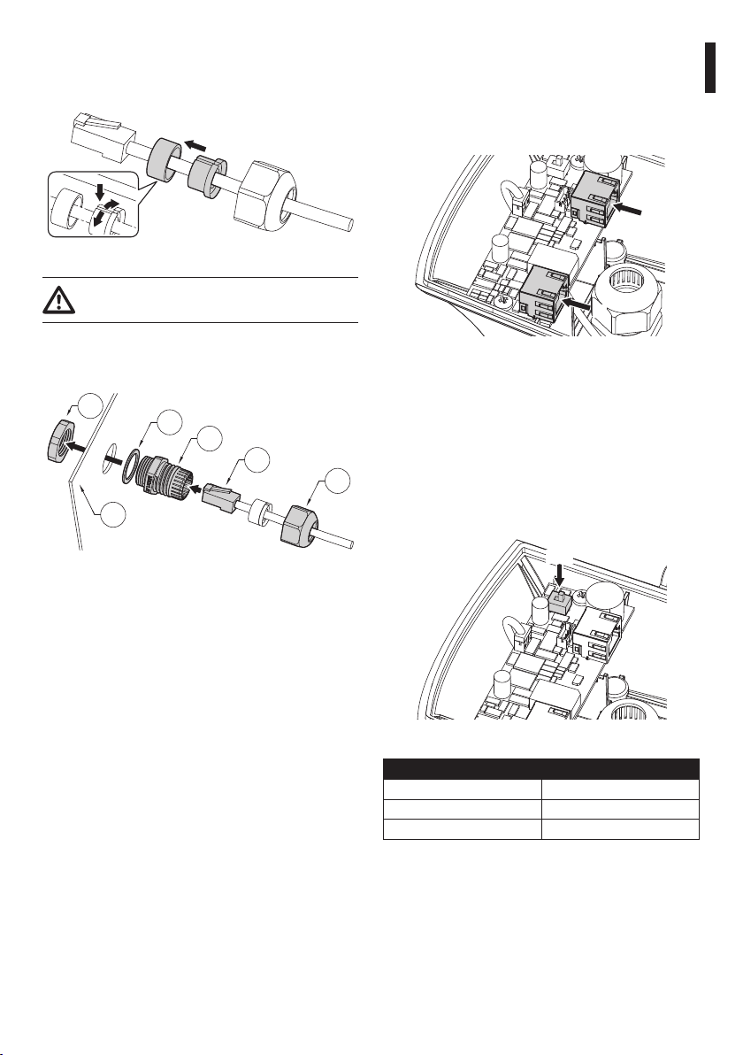
6.1.2 Cable glands assembly.......................................................................................................................................................... 5
6.1.3 Fixing the sunshield................................................................................................................................................................ 6
6.2 Installation.................................................................................................................................................................. 6
6.2.1 Fixing of housing to support............................................................................................................................................... 6
6.2.2 How to install the camera..................................................................................................................................................... 6
6.2.3 Ethernet cable installation ................................................................................................................................................... 7
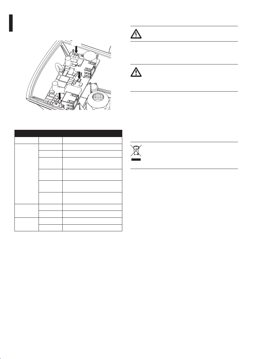
6.2.4 Connection of the PoE power supply board.................................................................................................................. 7
7 Conguration................................................................................................................. 7
7.1 Absorbed power conguration.......................................................................................................................... 7
7.2 Operating status....................................................................................................................................................... 8
7.3 Closing the housing................................................................................................................................................ 8
8 Maintaining and cleaning............................................................................................. 8
8.1 Window and plastic cover cleaning .................................................................................................................. 8
9 Disposal of waste materials.......................................................................................... 8
10 Technical data .............................................................................................................. 9
10.1 General...................................................................................................................................................................... 9
10.2 Mechanical............................................................................................................................................................... 9
10.3 Electrical ................................................................................................................................................................... 9
10.4 Environment............................................................................................................................................................ 9
10.5 Certications........................................................................................................................................................... 9
11 Technical drawings .................................................................................................... 10

Instructions manual - English - EN
3MNVCHEEPOE_1407_EN
1 About this manual
Before installing and using this unit, please read this
manual carefully. Be sure to keep it handy for later
reference.
1.1 Typographical conventions
DANGER!
High level hazard.
Risk of electric shock. Disconnect the
power supply before proceeding with any
operation, unless indicated otherwise.
WARNING!
Medium level hazard.
This operation is very important for the
system to function properly. Please read
the procedure described very carefully and
carry it out as instructed.
INFO
Description of system specications.
We recommend reading this part carefully
in order to understand the subsequent
stages.
2 Notes on copyright and
information on trademarks
The quoted names of products or companies are
trademarks or registered trademarks.
3 Safety rules
• The manufacturer declines all responsibility
for any damage caused by an improper use
of the appliances mentioned in this manual.
Furthermore, the manufacturer reserves the right
to modify its contents without any prior notice.
The documentation contained in this manual has
been collected with great care, the manufacturer,
however, cannot take any liability for its use. The
same thing can be said for any person or company
involved in the creation and production of this
manual.
• The device must be installed only and exclusively
by qualied technical personnel.
• Before starting any operation, make sure the
power supply is disconnected.
• Do not use cables that seem worn or old.
• Never, under any circumstances, make any
changes or connections that are not shown in
this handbook. Improper use of the appliance
can cause serious hazards, risking the safety of
personnel and of the installation.
• Use only original spare parts. Non-original spare
parts could cause re, electrical discharge or other
hazards.
• Before proceeding with installation check the
supplied material to make sure it corresponds
to the order specication by examining the
identication labels (4.2 Product markings, page 4).

EN - English - Instructions manual
4 MNVCHEEPOE_1407_EN
• This device was designed to be permanently
installed on a building or on a suitable structure.
The device must be installed permanently before
any operation.
• When installing the device, comply with all the
national standards.
• Any device which could be installed inside the
product must comply with the current safety
standards.
• For all connections, use cables that are able to
withstand temperatures of at least 75°C (167°F).
• Power supply to the product must be exclusively
provided by the PoE cable (Power over Ethernet).
• Use power supplies compliant with regulations
IEEE 802.3at/af and 60950-1.
• The product must be fastened with suitable
equipment. The fastening means must guarantee
the mechanical seal when a force equal to at least
4 times the weight of the device is applied.
4 Identification
4.1 Product description and type
designation
The PUNTO Hi-PoE housing exploits the PoE and Hi-
PoE technology in an optimal way, using the power
provided by the Ethernet cable as the sole source of
electricity to power the network camera along with
heating/demisting.
PUNTO Hi-PoE provides high reliability and exibility
of the network installation and simplies installation
operations with important cost reduction.
PUNTO Hi-PoE can be congured via a dip switch
according to the PoE or Hi-PoE standards depending
to the system requirements.
Very easy to install thanks to the side opening system
that allows the full access to the camera, lenses and
all internal connections.
The front is designed to oer protection from UV rays
and atmospheric agents.
4.2 Product markings
See the label attached to the product.

Instructions manual - English - EN
5MNVCHEEPOE_1407_EN
5 Preparing the product for
use
Any change that is not expressly approved
by the manufacturer will invalidate the
guarantee.
5.1 Unpacking and contents
5.1.1 Unpacking
When the product is delivered, make sure that the
package is intact and that there are no signs that it
has been dropped or scratched.
If there are obvious signs of damage, contact the
supplier immediately.
Keep the packaging in case you need to send the
product for repairs.
5.1.2 Contents
Check the contents to make sure they correspond
with the list of materials as below:
• Housing
• Housing equipment
• Instructions manual
• Desiccant bag
5.2 Safely disposing of packaging
material
The packaging material can all be recycled. The
installer technician will be responsible for separating
the material for disposal, and in any case for
compliance with the legislation in force where the
device is to be used.
When returning a faulty product we recommend
using the original packaging for shipping.
5.3 Preparatory work before
installation
5.3.1 Attaching the support
The product must be fastened with suitable
equipment. The fastening means must
guarantee the mechanical seal when a force
equal to at least 4 times the weight of the
device is applied.
6 Assembling and installing
The assembly and installation must be
performed only by skilled personnel.
6.1 Assembly
6.1.1 How to open the housing
Loosen the 2 screws on the side, turn the cover and
the upper half of the body about the opening hinge
axis.
Fig. 1
6.1.2 Cable glands assembly
The cable glands are suitable for cables with a
diameter between 5 and 10 mm.
Fix the cable glands as shown in the gure.
Fig. 2Support with external cable passage..
Fig. 3Support with internal cable passage..

EN - English - Instructions manual
6 MNVCHEEPOE_1407_EN
6.1.3 Fixing the sunshield
It’s possible to x the sunshield to the housing using
screws, washers and spacers provided.
Fig. 4
6.2 Installation
6.2.1 Fixing of housing to support
Apply a generous amount of thread locking
compound into the screw holes (Loctite
243®).
Fix the housing to the support using the supplied
screws.
Fig. 5Fixing on support with external cable passage.
Fig. 6Fixing on support with internal cable passage.
6.2.2 How to install the camera
Fasten the camera with the 1/4" screw. If necessary,
use the supplied spacers to correctly position the
camera and optics (03).
02
03
01
Fig. 7
Fasten down the adjustable slide in the correct
position using the appropriate screws.
Fig. 8

Instructions manual - English - EN
7MNVCHEEPOE_1407_EN
6.2.3 Ethernet cable installation
Insert the Ethernet cable in the gasket and block it as
shown in gure.
Fig. 9
Pay attention to the xing. Tightening
torque: 7Nm max.
Pass the cable with connector RJ45 (05) through the
M20 cable gland (02). Tighten the cable gland plug
(06).
02
01
05
06
04
03
Fig. 10
6.2.4 Connection of the PoE power
supply board
Connect the PoE cable from the Power Injector to the
J1 connector.
Connect the camera to the J2 connector.
J2
J1
Fig. 11
7 Configuration
7.1 Absorbed power
conguration
Before powering the device, you must set the
maximum power consumption of the housing
operating on dip switch SW1.
SW1
Fig. 12
ABSORBED POWER CONFIGURATION
SW1 Maximum power
POE PoE, class 3 (13W max)
POE+ Hi-PoE, class 4 (25W max)
Tab. 1

EN - English - Instructions manual
8 MNVCHEEPOE_1407_EN
7.2 Operating status
The LEDs shown in the gure allow to check the
product's operating status.
LD3
LD1
LD2
Fig. 13
Refer to the table to identify the operating status.
OPERATING STATUS
LED LED Status Apparatus Status
LD1 (Ca-
mera)
O The camera is not connected
On The camera is correctly powered
1 ashing The camera has a low identica-
tion resistance
2 ashings The camera has a high identica-
tion resistance
5 ashings The camera has an excessive
energy consumption
9 ashings The camera requires more energy
than the available
LD2 (Power
supply)
O The device is not powered
On The device is correctly powered
LD3 (He-
ater)
O Heating is inactive
On Heating is active
Tab. 2
7.3 Closing the housing
Take the dessicant salt bag out of its pack and insert
it into the product. Close the housing as soon as
possible to maintain the dessicant capability of the
salt bag.
8 Maintaining and cleaning
Before doing any technical work on the
device, disconnect the power supply.
8.1 Window and plastic cover
cleaning
Avoid ethyl alcohol, solvents, hydrogenated
hydrocarbide, strong acid and alkali. Such
products may irreparably damage the
surface.
Surface dirt should be rinsed away with water and
then the window cleaned with a neutral soap diluted
with water, or specic products for spectacle lens
cleaning. These should be applied with a soft cloth.
9 Disposal of waste
materials
This symbol mark and recycle system
are applied only to EU countries and not
applied to the countries in the other area of
the world.
Your product is designed and manufactured with
high quality materials and components which can be
recycled and reused.
This symbol means that electrical and electronic
equipment, at their end-of-life, should be disposed of
separately from your household waste.
Please dispose of this equipment at your local
Community waste collection or Recycling centre.
In the European Union there are separate collection
systems for used electrical and electronic products.

Instructions manual - English - EN
9MNVCHEEPOE_1407_EN
10 Technical data
10.1 General
Entirely made of technopolymer
RAL9002 Colour
Stainless steel external screws
10.2 Mechanical
Cable glands: 1xM20
Glass window (WxH): 60/95x63mm (2.4/3.7x2.5in)
Internal usable area (WxH): 70x70mm (2.7x2.7in)
Internal usable length: 250mm (9.8in)
Unit weight: 0.8kg (1.7lb)
10.3 Electrical
Power absorbed in input/Available power for camera
(selectable with dip-switch)
• PoE input Class 3 (13W): PoE camera Class 2 (7W)
• Hi-PoE input Class 4 (25W): PoE camera Class 3
(13W)
Data line: 10/100Base-T
Heater
• PoE input Class 3: 3W, Ton 15°C±3°C (59°F ±5°F),
To 22°C±3°C (77°F±5°F)
• Hi-PoE input Class 4: 7W, Ton 15°C±3°C (59°F
±5°F), To 22°C±3°C (77°F±5°F)
Demisting: 1W
Compatible with IEEE 802.3af, IEEE 802.3at/PoE Plus
10.4 Environment
Indoor/Outdoor
Operating temperature with heating: From -20°C
(-4°F) to +60°C (140°F)
Chemical agents resistance
• High resistance: basics, alcohols, gas, hydrocarbon
• Good resistance: Organic acids, inorganic acids,
oils
• Low resistance: Solvents
10.5 Certications
CE: EN61000-6-3, EN60950-1, EN50130-4
EN60529 IP66/IP67

MNVCHEEPOE_1407_EN
11 Technical drawings
The dimensions of the drawings are in
millimetres.
30
70
60
A - A B - B
14610170
77
109
139
146
57
62
31
118
65
391
B
B
300
424.2
300
31
A A
250 70
40
USABLE AREA
USABLE
AREA
Fig. 14 PUNTO Hi-PoE.
Headquarters Italy Videotec S.p.A.
Via Friuli, 6 - I-36015 - Schio (VI) Italy
Tel. +39 0445 697411 - Fax +39 0445 697414
Email: [email protected]
France Videotec France S.à.r.l.
Voie du Futur, Zac des Portes - 27100 - Val-de-Reuil, France
Tel. +33 2 32094900 - Fax +33 2 32094901
Email: info.fr@videotec.com
Asia Pacic Videotec (HK) Ltd
Flat 8, 19/F. - On Dak Industrial Building
2-6 Wah Sing Street - Kwai Chung, NT, Hong Kong
Tel. +852 2333 0601 - Fax +852 2311 0026
Email: info.hk@videotec.com
Americas Videotec Security, Inc.
35 Gateway Drive, Suite 100 - Plattsburgh, NY 12901 - U.S.A.
Tel. +1 518 825 0020 - Fax +1 518 825 0022
Email: info.usa@videotec.com - www.videotec.us
www.videotec.com

IT Italiano - Manuale di istruzioni
ITALIANO
PUNTO Hi-PoE
Custodia in tecnopolimero per telecamere IP

Sommario ITALIANO
1 Informazioni sul presente manuale ............................................................................. 3
1.1 Convenzioni tipograche ..................................................................................................................................... 3
2 Note sul copyright e informazioni sui marchi commerciali........................................ 3
3 Norme di sicurezza ........................................................................................................ 3
4 Identicazione ............................................................................................................... 4
4.1 Descrizione e designazione del prodotto....................................................................................................... 4
4.2 Marcatura del prodotto ......................................................................................................................................... 4
5 Preparazione del prodotto per l'utilizzo...................................................................... 5
5.1 Disimballaggio e contenuto ................................................................................................................................ 5
5.1.1 Disimballaggio.......................................................................................................................................................................... 5
5.1.2 Contenuto .................................................................................................................................................................................. 5
5.2 Smaltimento in sicurezza dei materiali di imballaggio.............................................................................. 5
5.3 Lavoro preparatorio prima dell’installazione................................................................................................. 5
5.3.1 Fissaggio del supporto.......................................................................................................................................................... 5
6 Assemblaggio e installazione....................................................................................... 5
6.1 Assemblaggio ........................................................................................................................................................... 5
6.1.1 Apertura della custodia......................................................................................................................................................... 5
6.1.2 Assemblaggio dei pressacavi.............................................................................................................................................. 5
6.1.3 Fissaggio del tettuccio........................................................................................................................................................... 6
6.2 Installazione............................................................................................................................................................... 6
6.2.1 Fissaggio della custodia al supporto................................................................................................................................ 6
6.2.2 Installazione della telecamera ............................................................................................................................................ 6
6.2.3 Installazione del cavo Ethernet .......................................................................................................................................... 7
6.2.4 Collegamento della scheda alimentatore PoE.............................................................................................................. 7
7 Congurazione .............................................................................................................. 7
7.1 Congurazione potenza assorbita .................................................................................................................... 7
7.2 Stato di funzionamento......................................................................................................................................... 8
7.3 Chiusura della custodia ......................................................................................................................................... 8
8 Manutenzione e pulizia................................................................................................. 8
8.1 Pulizia del vetro e delle parti in plastica .......................................................................................................... 8
9 Smaltimento dei riuti.................................................................................................. 8
10 Dati tecnici ................................................................................................................... 9
10.1 Generale ................................................................................................................................................................... 9
10.2 Meccanica ................................................................................................................................................................ 9
10.3 Elettrico..................................................................................................................................................................... 9
10.4 Ambiente.................................................................................................................................................................. 9
10.5 Certicazioni ........................................................................................................................................................... 9
11 Disegni tecnici ........................................................................................................... 10

Manuale di istruzioni - Italiano - IT
3MNVCHEEPOE_1407_IT
1 Informazioni sul presente
manuale
Prima di installare e utilizzare questa unità, leggere
attentamente questo manuale. Conservare questo
manuale a portata di mano come riferimento futuro.
1.1 Convenzioni tipograche
PERICOLO!
Pericolosità elevata.
Rischio di scosse elettriche. Prima di
eseguire qualsiasi operazione assicurarsi di
togliere tensione al prodotto, salvo diversa
indicazione.
ATTENZIONE!
Pericolosità media.
L'operazione è molto importante per il
corretto funzionamento del sistema. Si
prega di leggere attentamente la procedura
indicata e di eseguirla secondo le modalità
previste.
INFO
Descrizione delle caratteristiche del
sistema.
Si consiglia di leggere attentamente per
comprendere le fasi successive.
2 Note sul copyright e
informazioni sui marchi
commerciali
I nomi di prodotto o di aziende citati sono marchi
commerciali o marchi commerciali registrati
appartenenti alle rispettive società.
3 Norme di sicurezza
• Il produttore declina ogni responsabilità per
eventuali danni derivanti da un uso improprio
delle apparecchiature menzionate in questo
manuale. Si riserva inoltre il diritto di modicarne
il contenuto senza preavviso. Ogni cura è
stata posta nella raccolta e nella verica della
documentazione contenuta in questo manuale,
tuttavia il produttore non può assumersi alcuna
responsabilità derivante dall'utilizzo della stessa.
Lo stesso dicasi per ogni persona o società
coinvolta nella creazione e nella produzione di
questo manuale.
• L'installazione e la manutenzione del dispositivo
deve essere eseguita solo da personale tecnico
qualicato.
• Prima di eseguire qualsiasi operazione assicurarsi
di togliere tensione al prodotto.
• Non utilizzare cavi con segni di usura o
invecchiamento.
• Non eettuare per nessun motivo alterazioni o
collegamenti non previsti in questo manuale.
L'uso di apparecchi non idonei può portare a
gravi pericoli per la sicurezza del personale e
dell'impianto.
• Utilizzare solo parti di ricambio originali. Pezzi di
ricambio non originali potrebbero causare incendi,
scariche elettriche o altri pericoli.
• Prima di procedere con l'installazione controllare
che il materiale fornito corrisponda alle speciche
richieste esaminando le etichette di marcatura (4.2
Marcatura del prodotto, pagina 4).

IT - Italiano - Manuale di istruzioni
4 MNVCHEEPOE_1407_IT
• Questo dispositivo è stato progettato per essere
installato in maniera permanente su un edicio
o su una struttura adeguata. Il dispositivo deve
essere installato in maniera permanente prima di
eettuare qualsiasi operazione.
• Si devono rispettare le normative nazionali per
l'installazione del dispositivo.
• Ogni dispositivo che può essere installato
all’interno del prodotto deve essere conforme alle
norme di sicurezza attuali.
• Per tutte le connessioni, utilizzare cavi idonei a
sopportare temperature di almeno 75°C.
• L'alimentazione del prodotto deve essere fornita
esclusivamente dal cavo PoE (Power over Ethernet).
• Utilizzare alimentatori conformi alle normative IEEE
802.3at/af e 60950-1.
• Il prodotto deve essere ssato con mezzi adeguati.
I mezzi di ssaggio devono garantire la tenuta
meccanica applicando una forza pari almeno a 4
volte il peso complessivo dell’apparecchiatura.
4 Identificazione
4.1 Descrizione e designazione
del prodotto
La custodia PUNTO Hi-PoE sfrutta in maniera ottimale
la tecnologia POE e Hi-POE utilizzando la potenza
resa disponibilie dal cavo Ethernet come unica
fonte di alimentazione per alimentare la telecamera
network ed il riscaldamento/disappannamento.
PUNTO Hi-PoE ore una maggiore adabilità e
essibilità dell’impianto network e semplica le
operazioni d’installazione con conseguente riduzione
dei costi.
PUNTO Hi-PoE può essere congurata tramite un
dip- switch secondo lo standard PoE oppure Hi-PoE in
base alle esigenze dell'impianto.
Estremamente semplice da installare, l’apertura
laterale facilita ampiamente l’accesso alla telecamera,
alle ottiche e a tutte le connessioni interne.
Il frontale è disegnato in modo da garantire
protezione dai raggi solari e dagli agenti atmosferici.
4.2 Marcatura del prodotto
Vedere l’etichetta posta sul prodotto.

Manuale di istruzioni - Italiano - IT
5MNVCHEEPOE_1407_IT
5 Preparazione del
prodotto per l'utilizzo
Qualsiasi cambiamento non espressamente
approvato dal costruttore fa decadere la
garanzia.
5.1 Disimballaggio e contenuto
5.1.1 Disimballaggio
Alla consegna del prodotto vericare che l'imballo
sia integro e non abbia segni evidenti di cadute o
abrasioni.
In caso di evidenti segni di danno all'imballo
contattare immediatamente il fornitore.
Conservare l'imballo nel caso sia necessario inviare il
prodotto in riparazione.
5.1.2 Contenuto
Controllare che il contenuto sia corrispondente alla
lista del materiale sotto elencata:
• Custodia
• Dotazione per custodia
• Manuale di istruzioni
• Sacchetto disidratante
5.2 Smaltimento in sicurezza dei
materiali di imballaggio
I materiali d'imballo sono costituiti interamente da
materiale riciclabile. Sarà cura del tecnico installatore
smaltirli secondo le modalità di raccolta dierenziata
o comunque secondo le norme vigenti nel Paese di
utilizzo.
In caso di restituzione del prodotto malfunzionante
è consigliato l'utilizzo dell'imballaggio originale per
il trasporto.
5.3 Lavoro preparatorio prima
dell’installazione
5.3.1 Fissaggio del supporto
Il prodotto deve essere ssato con mezzi
adeguati. I mezzi di ssaggio devono
garantire la tenuta meccanica applicando
una forza pari almeno a 4 volte il peso
complessivo dell’apparecchiatura.
6 Assemblaggio e
installazione
L'assemblaggio e l'installazione vanno
eseguiti solo da personale qualicato.
6.1 Assemblaggio
6.1.1 Apertura della custodia
Svitare le 2 viti poste sul anco, far ruotare tettuccio
e corpo superiore attorno all’asse delle cerniere di
apertura.
Fig. 1
6.1.2 Assemblaggio dei pressacavi
I pressacavi sono adatti a cavi con diametro compreso
tra 5 e 10mm.
Fissare i pressacavi come illustrato in gura.
Fig. 2Supporto per passaggio esterno dei cavi.
Fig. 3Supporto con passaggio interno dei cavi.

IT - Italiano - Manuale di istruzioni
6 MNVCHEEPOE_1407_IT
6.1.3 Fissaggio del tettuccio
È possibile ssare il tettuccio alla custodia utilizzando
viti, rondelle e distanziali forniti in dotazione.
Fig. 4
6.2 Installazione
6.2.1 Fissaggio della custodia al
supporto
Applicare nei fori delle viti una buona
quantità di frenaletti (Loctite 243®).
Fissare la custodia al supporto utilizzando le viti
fornite in dotazione.
Fig. 5Fissaggio su supporto con passaggio esterno dei cavi.
Fig. 6Fissaggio su supporto con passaggio interno dei cavi.
6.2.2 Installazione della telecamera
Fissare la telecamera con la vite da 1/4". Se necessario
utilizzare i distanziali in dotazione per collocare nel
modo corretto la telecamera e l'ottica (03).
02
03
01
Fig. 7
Fissare la slitta regolabile nella posizione corretta con
le apposite viti.
Fig. 8

Manuale di istruzioni - Italiano - IT
7MNVCHEEPOE_1407_IT
6.2.3 Installazione del cavo Ethernet
Inserire il cavo Ethernet nella guarnizione e bloccare il
tutto come illustrato in gura.
Fig. 9
Prestare attenzione durante il ssaggio.
Coppia di serraggio: 7Nm max.
Far passare il cavo con connettore RJ45 (05)
attraverso il pressacavo M20 (02). Avvitare il tappo del
pressacavo (06).
02
01
05
06
04
03
Fig. 10
6.2.4 Collegamento della scheda
alimentatore PoE
Collegare il cavo PoE proveniente dal Power Injector
al connettore J1.
Collegare la telecamera al connettore J2.
J2
J1
Fig. 11
7 Configurazione
7.1 Congurazione potenza
assorbita
Prima di alimentare il dispositivo è necessario
impostare la potenza massima assorbita dalla
custodia agendo sul dip-switch SW1.
SW1
Fig. 12
CONFIGURAZIONE POTENZA ASSORBITA
SW1 Potenza massima
POE PoE, classe 3 (13W max)
POE+ Hi-PoE, classe 4 (25W max)
Tab. 1

IT - Italiano - Manuale di istruzioni
8 MNVCHEEPOE_1407_IT
7.2 Stato di funzionamento
I LED illustrati in gura permettono in qualsiasi
momento di vericare lo stato di funzionamento del
prodotto.
LD3
LD1
LD2
Fig. 13
Fare riferimento alla tabella per identicare lo stato di
funzionamento.
STATO DI FUNZIONAMENTO
LED Stato LED Stato Apparato
LD1 (Teleca-
mera)
Spento La telecamera non è connessa
Acceso La telecamera è alimentata in
modo corretto
1 lampeg-
gio
La telecamera ha una resistenza
di identicazione bassa
2 lampeggi La telecamera ha una resistenza
di identicazione alta
5 lampeggi La telecamera ha un consumo
eccessivo
9 lampeggi La telecamera richiede più poten-
za di quella disponibile
LD2
(Alimenta-
zione)
Spento Il dispositivo non è alimentato
Acceso Il dispositivo è alimentato corret-
tamente
LD3 (Riscal-
damento)
Spento Il riscaldamento è inattivo
Acceso Il riscaldamento è attivo
Tab. 2
7.3 Chiusura della custodia
Estrarre il sacchetto disidratante dalla confezione
e inserirlo nel prodotto. Chiudere la custodia al più
presto al ne di mantenerne la capacità disidratante.
8 Manutenzione e pulizia
Prima di eettuare interventi tecnici
sull’apparecchio togliere l’alimentazione
elettrica.
8.1 Pulizia del vetro e delle parti
in plastica
Evitare alcool etilico, solventi, idrocarburi
idrogenati, acidi forti e alcali. L’utilizzo
di detti prodotti danneggia in modo
irreparabile la supercie trattata.
Si consigliano saponi neutri diluiti con acqua o
prodotti specici per la pulizia delle lenti degli
occhiali con l’utilizzo di un panno morbido.
9 Smaltimento dei rifiuti
Questo simbolo e il sistema di riciclaggio
sono validi solo nei paesi dell'EU e non
trovano applicazione in altri paesi del
mondo.
Il vostro prodotto è costruito con materiali e
componenti di alta qualità, che sono riutilizzabili o
riciclabili.
Prodotti elettrici ed elettronici che portano questo
simbolo alla ne dell'uso devono essere smaltiti
separatamente dai riuti casalinghi.
Vi preghiamo di smaltire questo apparecchio in un
Centro di raccolta o in un'Ecostazione.
Nell'Unione Europea esistono sistemi di raccolta
dierenziata per prodotti elettrici ed elettronici.
Table of contents
Languages:
Other Videotec IP Camera manuals