Videotec TWT User manual

MANUALE
D’USO

Pag. 1TWT9605
INDICE
INDICE.................................................................................................................................................................................... 1
INTRODUZIONE.................................................................................................................................................................... 2
Contenuto dell’imballo............................................................................................................................................................................... 2
Cosa contiene questo manuale................................................................................................................................................................. 2
Convenzioni tipografiche........................................................................................................................................................................... 2
NORME DI SICUREZZA........................................................................................................................................................ 2
DATI DI MARCATURA........................................................................................................................................................... 3
DESCRIZIONE DEL TRASMETTITORE TWT...................................................................................................................... 3
Caratteristiche........................................................................................................................................................................................... 3
INSTALLAZIONE................................................................................................................................................................... 3
Apertura dell’imballaggio........................................................................................................................................................................... 3
Controllo della marcatura.......................................................................................................................................................................... 3
CONFIGURAZIONE DEL TRASMETTITORE TWT.............................................................................................................. 4
Trimmers e jumpers di configurazione ...................................................................................................................................................... 4
Procedura di configurazione...................................................................................................................................................................... 4
Impostazione dell’impedenza di uscita.................................................................................................................................................. 4
Impostazione del guadagno del pre-amplificatore..................................................................................................................................... 4
Test del segnale video .............................................................................................................................................................................. 5
COLLEGAMENTI................................................................................................................................................................... 5
Esempio di installazione............................................................................................................................................................................ 5
Collegamento dell’unità TWT.................................................................................................................................................................... 5
Collegamento dell’ingresso video.......................................................................................................................................................... 5
Collegamento dell’uscita bifilare............................................................................................................................................................ 5
Collegamento dell’alimentazione........................................................................................................................................................... 5
ACCENSIONE E SPEGNIMENTO......................................................................................................................................... 6
MANUTENZIONE................................................................................................................................................................... 6
RISOLUZIONE DI PROBLEMI .............................................................................................................................................. 6
CARATTERISTICHE TECNICHE .......................................................................................................................................... 6
Il produttore declina ogni responsabilità per eventuali danni derivanti da un uso improprio delle apparecchiature
menzionate in questo manuale; si riserva inoltre il diritto di modificarne il contenuto senza preavviso.
Ogni cura é stata posta nella raccolta e nella verifica della documentazione contenuta in questo manuale:
tuttavia il produttore non può assumersi alcuna responsabilità derivante dall’utilizzo della stessa. Lo stesso dicasi
per ogni persona o società coinvolta nella creazione e nella produzione di questo manuale.

Pag. 2TWT9605
Introduzione
Contenuto dell’imballo
• 1 trasmettitore TWT
• 1 manuale d’uso
Alla consegna del prodotto verificare che l’imballo sia integro e non abbia segni evidenti di cadute o abrasioni. In caso
di evidenti segni di danno all’imballo contattare immediatamente il fornitore.
Controllare che il contenuto sia rispondente alla lista del materiale sopra indicata.
Cosa contiene questo manuale
In questo manuale è descritto il trasmettitore TWT, con le particolari procedure di installazione, configurazione e
utilizzo. E’ necessario leggere attentamente questo manuale, in particolar modo il capitolo concernente le norme di
sicurezza, prima di installare ed utilizzare il trasmettitore.
Convenzioni tipografiche
Nel presente manuale si fa uso di diversi simboli grafici, il cui significato è riassunto di seguito:
Rischio di scariche elettriche; togliere l’alimentazione prima di procedere con le operazioni, se non é
espressamente indicato il contrario.
L’operazione é molto importante per il corretto funzionamento del sistema: si prega di leggere attentamente la
procedura indicata, ed eseguirla secondo le modalità previste.
Descrizione delle caratteristiche del sistema: si consiglia di leggere attentamente per comprendere le fasi
successive.
Norme di sicurezza
Il trasmettitore TWT é conforme alle normative vigenti all’atto della pubblicazione del presente manuale per
quanto concerne la sicurezza elettrica, la compatibilità elettromagnetica ed i requisiti generali.
Si desidera tuttavia garantire gli utilizzatori (tecnico installatore e operatore) specificando alcune avvertenze per
operare nella massima sicurezza:
• Collegare ad una linea di alimentazione corrispondente a quella indicata sulle etichette di marcatura (vedere il
successivo capitolo Dati di marcatura)
• Prima di spostare o effettuare interventi tecnici sull’apparecchio, disinserire l’alimentazione
• Non utilizzare cavi di tensione con segni di usura o invecchiamento, in quanto rappresentano un grave pericolo per
l’incolumità degli utilizzatori
• L’installazione dell’apparecchio (e dell’intero impianto di cui esso fa parte) deve essere effettuata da personale
tecnico adeguatamente qualificato
• L’apparecchio deve essere aperto soltanto da personale tecnico qualificato. La manomissione dell’apparecchio fa
decadere i termini di garanzia
• Non utilizzare l’apparecchio in presenza di sostanze infiammabili
• Non permettere l’uso dell’apparecchio a bambini o incapaci
• Accertarsi che l’apparecchio sia fissato in maniera solida e affidabile
• L’apparecchio si considera disattivato soltanto quando l’alimentazione é disinserita e i cavi di collegamento con altri
dispositivi sono stati rimossi
• Per l’assistenza tecnica rivolgersi esclusivamente al personale tecnico autorizzato
• Conservare con cura il presente manuale per ogni futura consultazione

Pag. 3TWT9605
Dati di marcatura
Sul trasmettitore TWT sono riportate due etichette conformi alla marcatura CE.
La prima etichetta contiene:
• Codice di identificazione del modello (Codice a barre Extended 3/9 )
• Tensione di alimentazione (Volt)
• Frequenza (Hertz)
• Consumo (Watt)
La seconda etichetta indica il numero di serie del modello (codice a barre Extended 3/9)
All’atto dell’installazione controllare se le caratteristiche di alimentazione del trasmettitore corrispondono a quelle
richieste. L’uso di apparecchi non idonei può portare a gravi pericoli per la sicurezza del personale e dell’impianto.
Descrizione del trasmettitore TWT
L’unità TWT è un trasmettitore bifilare di segnale video. Se collegato al ricevitore TWRB/TWRR, permette la
trasmissione del segnale video su 2 fili.
Caratteristiche
• Sistema completamente compatibile con il colore
• Notevoli distanze di trasmissione : una coppia trasmettitore/ricevitore può essere impiegata su tratte da uno a due
chilometri. Mediante l’uso di amplificatori intermedi, si possono raggiungere distanze di 3,4 chilometri
• Nessun problema causato da eventuali LOOP verso terra
• Altissima immunità ai disturbi elettromagnetici
• Ottimizzazione all’equazione in frequenza
• Economicità e praticità
• Piccole dimensioni
• Alimentazione AC / DC
• Protezione contro le sovratensioni
• Scelta dell’impedenza di uscita
• Pre-amplificatore +10 dB / 5 Mhz
Installazione
La fase di installazione deve essere effettuata solo da personale tecnico qualificato.
Apertura dell’imballaggio
Se l’imballo non presenta evidenti difetti (dovuti a cadute o abrasioni anomale), procedere al controllo del materiale in
esso contenuto, secondo la lista fornita al paragrafo Contenuto dell’imballo al capitolo Introduzione.
I materiali d’imballo sono costituiti interamente da materiale riciclabile. Sarà cura del tecnico installatore smaltirli
secondo le modalità di raccolta differenziata o comunque secondo le norme vigenti nel Paese di utilizzo.
Controllo della marcatura
Prima di procedere con l’installazione controllare se il materiale fornito corrisponde alle specifiche richieste,
esaminando le etichette di marcatura, secondo quanto descritto al capitolo Dati di marcatura.
Non effettuare per nessun motivo alterazioni o collegamenti non previsti in questo manuale: l’uso di apparecchi non
idonei può portare a gravi pericoli per la sicurezza del personale e dell’impianto.

Pag. 4TWT9605
Configurazione del trasmettitore TWT
Trimmers e jumpers di configurazione
Nella figura seguente identificare i trimmers ed i jumpers di configurazione :
Procedura di configurazione
Le seguenti procedure sono da effettuare in assenza di alimentazione, se non diversamente indicato
La procedura di configurazione consente di predisporre l’unità ad un funzionamento ottimale e deve essere
effettuata solo da personale tecnico qualificato. Le operazioni da eseguire in fase di configurazione sono le seguenti :
1. Impostazione dell’impedenza di uscita
2. Impostazione del guadagno del pre-amplificatore
Impostazione dell’impedenza di uscita
L’impedenza di uscita deve assumere valori diversi a seconda del tipo di cavo utilizzato per la trasmissione del
segnale video dall’unità TWT al ricevitore TWRB/TWRR:
• Per cavi isolati in PE o carta : regolare l’impedenza di uscita a 125 Ohm
• Per cavi in PVC : regolare l’impedenza di uscita a 90 Ohm
Dove agire: Jumper J2
Impostazioni :
• Impedenza 90 Ohm: posizionare J2 come mostrato nella figura ( posizione 90 Ohm )
• Impedenza 125 Ohm : posizionare J2 nella posizione 125 Ohm
Impostazione del guadagno del pre-amplificatore
Dove agire: Jumper J1
Impostazioni :
• Guadagno a 0 dB: posizionare J1 come mostrato nella figura ( posizione 0 dB )
• Guadagno a +10 dB : posizionare J1 nella posizione +10 dB
Alimentazione
AC / DC
GND
IN
Ingresso
video
Uscita
bifilare

Pag. 5TWT9605
Test del segnale video
La seguente procedura deve essere seguita per la verifica in laboratorio del funzionamento dell’unità TWT.
1. Settare il Jumper J1 in posizione 0 dB
2. Collegare una telecamera ( o un qualsiasi segnale video 1 Vpp - 75 Ohm ) al connettore K1
3. Collegare l’alimentazione ( AC / DC ) al connettore K3
4. Alimentare il trasmettitore TWT
5. Alimentare la telecamera
6. Controllare, con un oscilloscopio, che tra i punti A e GND ci sia un segnale di +2 Vpp a circuito aperto
7. Controllare, con un oscilloscopio, che tra i punti B e GND ci sia un segnale di -2 Vpp a circuito aperto
8. Togliere l’alimentazione all’unità TWT
9. Togliere l’alimentazione alla telecamera
Collegamenti
Esempio di installazione
Il segnale video della telecamera in ingresso al trasmettitore TWT viene visualizzato sul monitor collegato in uscita al
ricevitore TWRB/TWRR; il segnale video è trasmesso attraverso un cavo bifilare :
MATERIALE IMPIEGATO
Parte video:
• 1 monitor
• 1 telecamera
• 1 trasmettitore TWT
• 1 ricevitore TWRB/TWRR
Collegamento dell’unità TWT
Collegamento dell’ingresso video
Dove agire : morsettiera K1 del trasmettitore TWT
Impostazioni : collegare il segnale video proveniente dalla telecamera alla morsettiera K1
Collegamento dell’uscita bifilare
Dove agire : morsettiera K2 del trasmettitore TWT, morsettiera K3 del ricevitore TWRB/TWRR
Impostazioni : collegare i morsetti con il cavo bifilare secondo la tabella seguente
Trasmettitore TWT : morsettiera K2 Ricevitore TWRB/TWRR : morsettiera K3
morsetto A ------------ ------------ morsetto A
morsetto B ------------ ------------ morsetto B
Per il collegamento utilizzare solo doppino telefonico twistato non schermato
Collegamento dell’alimentazione
Dove agire : morsettiera K3 del trasmettitore TWT
Impostazioni : collegare l’alimentazione alla morsettiera K3
TWT
TWRB/TWRR

Pag. 6TWT9605
Accensione e spegnimento
Prima di fornire alimentazione:
• controllare se il materiale fornito corrisponde alle specifiche richieste, esaminando le etichette di marcatura,
secondo quanto descritto al capitolo Dati di marcatura.
• controllare che il trasmettitore TWT e gli altri componenti dell’impianto siano chiusi e sia quindi impossibile il
contatto diretto con parti in tensione.
• accertarsi che tutte le parti siano fissate in maniera solida ed affidabile
• controllare che le fonti di alimentazione ed i cavi di collegamento siano in grado di sopportare il consumo del
sistema
ACCENSIONE: il trasmettitore non è fornito di interruttore di accensione : fornire alimentazione all’unità.
SPEGNIMENTO: togliere alimentazione all’unità
Manutenzione
Il trasmettitore TWT non necessita di particolare manutenzione.
Si raccomanda di utilizzarlo poggiato su una base solida, con i cavi di alimentazione e di collegamento in posizione tale
da non essere causa di intralcio all’operatore.
Risoluzione di problemi
Il trasmettitore TWT è caratterizzato da una notevole facilità d’uso, ma ciononostante possono insorgere dei problemi
sia in fase di installazione o durante l’uso.
Problema Possibile causa Intervento correttivo
All’accensione il segnale video
non viene visualizzato in uscita Manca alimentazione Controllare il cavo di alimentazione
Collegamenti errati Controllare i collegamenti secondo
quanto descritto al capitolo Collegamenti
Il trasmettitore TWT non funziona Eseguire la procedura di test descritta al
capitolo Test del segnale video
Il ricevitore TWRB/TWRR non
funziona Fare riferimento al manuale d’uso del
ricevitore TWRB/TWRR
Caratteristiche tecniche
Tensione d’alimentazione: 20 V --- 30 V, AC / DC, 100mA max (riferirsi ai dati di marcatura)
Ingresso video: 1 Vpp, 75 Ohm
Uscita video: 2x2 Vpp
Impedenza d’uscita: 125 Ohm / 90 Ohm
Risposta in frequenza: 30 Hz - 5 Mhz ( -0.5 dB )
Pre-amplificatore: +10 dB, 5 Mhz
Protezione per l’alimentazione: Varistore
Dimensioni: 105x55x80 mm
Grado di protezione: IP-65 (VDE)

OPERATING
INSTRUCTIONS

Pag. 1TWT9605
INDEX
INDEX..................................................................................................................................................................................... 1
INTRODUCTION.................................................................................................................................................................... 2
Packing contents....................................................................................................................................................................................... 2
Contents of this Manual............................................................................................................................................................................. 2
Typographic conventions........................................................................................................................................................................... 2
SAFETY RULES .................................................................................................................................................................... 2
IDENTIFICATION DATA........................................................................................................................................................ 3
DESCRIPTION OF TWT TRANSMITTER............................................................................................................................. 3
Features.................................................................................................................................................................................................... 3
INSTALLATION ..................................................................................................................................................................... 3
Unpacking ................................................................................................................................................................................................. 3
Check of identification data....................................................................................................................................................................... 3
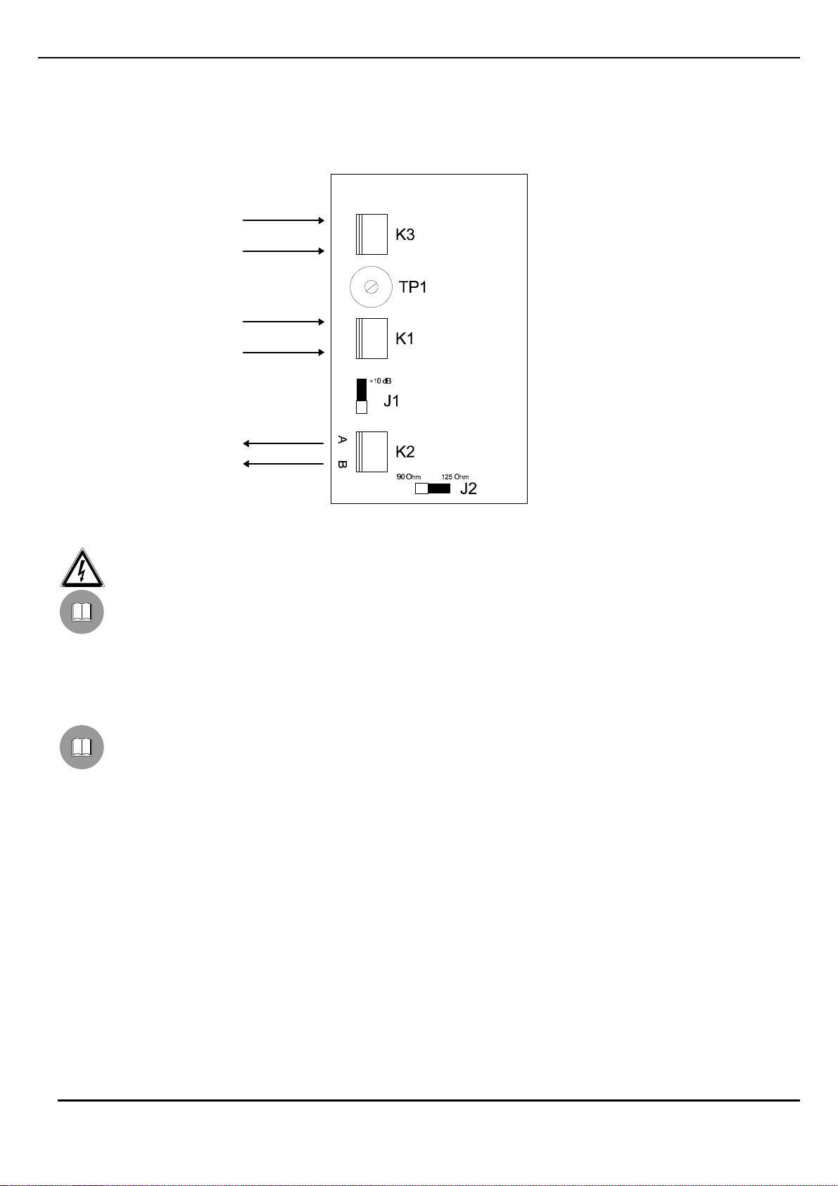
CONFIGURATION OF TWT TRANSMITTER ....................................................................................................................... 4
Configuration jumpers and trimmers......................................................................................................................................................... 4
Configuration procedure............................................................................................................................................................................ 4
Output impedence adjustment............................................................................................................................................................... 4
Pre-amplifier gain adjustment.................................................................................................................................................................... 4
Video signal test........................................................................................................................................................................................ 5
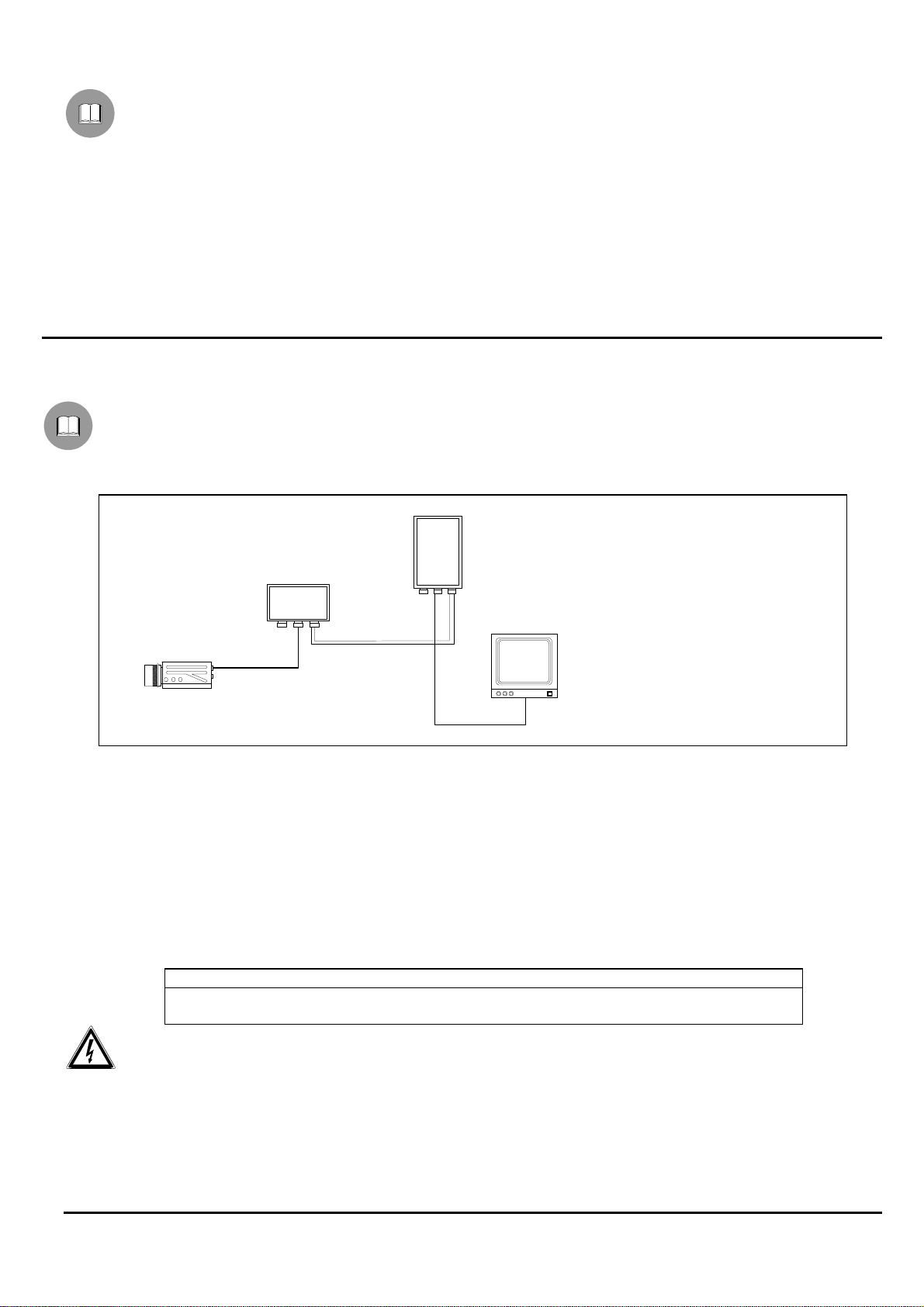
CONNECTIONS..................................................................................................................................................................... 5
Installation example................................................................................................................................................................................... 5
Connection of TWT unit............................................................................................................................................................................. 5
Video input connection.......................................................................................................................................................................... 5
Twisted pair output connection.............................................................................................................................................................. 5
Power supply connection ...................................................................................................................................................................... 5
SWITCHING ON AND OFF.................................................................................................................................................... 6
MAINTENANCE ..................................................................................................................................................................... 6
PROBLEM SOLUTION.......................................................................................................................................................... 6
SPECIFICATIONS.................................................................................................................................................................. 6
The manufacturer declines all responsibility for any damage caused by an improper use of the appliances
mentioned in this manual; furthermore, the manufacturer reserves the right to modify its contents without any
prior notice.
The documentation contained in this manual has been collected with great care: the manufacturer, however,
cannot take any liability for its use. The same thing can be said for any person or company involved in the
creation and production of this manual.

Pag. 2TWT9605
Introduction
Packing contents
• 1 transmitter TWT
• 1 instruction manual
After the delivery, check that the packing is not damaged and shows no evident signs of falls or abrasions. Should this
be so, contact immediately the supplier.
Check that the contents correspond to the above-mentioned list of materials.
Contents of this Manual
This manual describes the TWT transmitter together with its specific procedures of installation, configuration and use.
Read this manual carefully, in particular the chapter concerning the safety rules, before installing and using the
transmitter.
Typographic conventions
Different graphic symbols are used in this manual, the meaning of which is here described:
Hazard of electric shock; disconnect the power supply before proceeding, if not otherwise specified.
The operation is very important for the correct working of the system: read carefully the procedure indicated,
and carry it out according to the required modalities.
Description of system features: read carefully to understand the following phases.
Safety rules
TWT transmitter complies with the normative laws in force at the time of editing of this manual, concerning
electric safety, electromagnetic compatibility and general requirements.
Anyway, in order to ensure the users (installer technician and operator), the following warnings are specified for
safety’s sake:
• Connect to a feeder corresponding to the specifications indicated on the data plate (see next chapter Identification
data)
• Before any shifting or technical operations on the appliance, unplug it from the mains
• Do not use voltage cables showing wear or ageing, since they may seriously compromise the users’ safety
• The appliance (and the complete system, which it belongs to) must be installed only by qualified technical staff
• The appliance must be opened only by qualified technical staff. The tampering of the appliance may void the
guarantee terms.
• Do not use the appliance in the presence of inflammable substances
• Do not allow children or people not familiar with the appliance to use it
• Make sure the appliance is fixed in a solid and reliable way
• The appliance is completely off-line only when the plug is diconnected and the cables connected to other appliances
have been removed
• For after-sale service call only authorised technical staff.
• Keep this manual close to hand for any future reference

Pag. 3TWT9605
Identification data
On TWT transmitter there are two plates complying with EC specifications.
The first plate includes:
• Model identification code (Extended bar code 3/9 )
• Mains voltage (Volt)
• Frequency (Hertz)
• Power consumption (Watt)
The second plate shows the model serial number (Extended bar code 3/9)
When installing the appliance, check that the power supply specifications of the receiver correspond to those required.
The use of improper appliances may seriously compromise the safety of the personnel and the installation.
Description of TWT transmitter
TWT unit is a twisted pair video transmitter. If connected to TWRB/TWRR receiver, it allows the transmission
of the video signal over 2 wires.
Features
• Completely compatible with colour
• Remarkable transmission distances : a couple transmitter/receiver can be used for distances from one to two
kilometers. By means of intermediate amplifiers, it is possible to reach distances up to 3, 4 kilometers
• No trouble arising from possible ground LOOPS
• High protection against electromagnetic noises
• Optimization to frequency equation
• Cheapness and convenience
• Small dimensions
• AC / DC power supply
• Overvoltage protection
• Output impedence choice
• Pre-amplifier + 10 dB / 5 Mhz
Installation
The installation must be carried out only by qualified technical staff.
Unpacking
If the packing shows no relevant defects (due to falls or anomalous abrasions), check the material contained,
according to the list given at paragraph Packing contents chapter Introduction.
The packing materials can be completely recycled. The installer technician is required to dispose of them according to
the differentiated collecting modalities or ,anyway, according to the normative laws in force in the Country of use.
Check of identification data
Before installing the appliance, check that the material supplied corresponds to the specifications indicated on
the data plate, following the chapter Identification data. Do not carry out any modification or connections which are not
provided for in this manual: the use of improper appliances may seriously compromise the safety of the personnel and
the installation.

Pag. 4TWT9605
Configuration of TWT transmitter
Configuration jumpers and trimmers
In the following drawing, identify the configuration jumpers and trimmers :
Configuration procedure
The following procedures must be carried out with power supply off, if not otherwise specified
The configuration procedure prepares the unit for perfect working and must be carried out only by qualified
technical staff. The operations to perform during the configuration phase are the following:
1. Output impedence adjustment
2. Pre-amplifier gain adjustment
Output impedence adjustment
The output impedence has to assume different values according to the type of cable used for the video signal
transmission from TWT unit to TWRB/TWRR receiver:
• For PE or paper insulated cables : adjust the output impedence to 125 Ohm
• For PVC cables : adjust the output impedence to 90 Ohm
Where to operate : Jumper J2
Adjustments :
• 90 Ohm impedence : set J2 as shown in the drawing ( 90 Ohm position )
• 125 Ohm impedence: set J2 at 125 Ohm position
Pre-amplifier gain adjustment
Where to operate : Jumper J1
Adjustments :
• Gain at 0 dB: set J1 as shown in the drawing ( 0 dB position )
• Gain at +10 dB : set J1 at +10 dB position
AC / DC
Power supply
GND
IN
Video
input
Twisted pair
output

Pag. 5TWT9605
Video signal test
The following procedure must be carried out for a laboratory check of TWT working.
1. Set Jumper J1 at 0 dB position
2. Connect a telecamera ( or any video signal 1 Vpp - 75 Ohm ) to K1 connector
3. Connect the power supply ( AC / DC ) to K3 connector
4. Feed TWT transmitter
5. Feed the telecamera
6. By means of an oscilloscope, check if a signal +2 Vpp at open circuit is present between points A and GND
7. By means of an oscilloscope, check if a signal -2 Vpp at open circuit is present between points B and GND
8. Disconnect the power supply of TWT unit
9. Disconnect the power supply of the telecamera
Connections
Installation example
The telecamera video signal in TWT input is displayed on the monitor connected to TWRB/TWRR output; the video
signal is transmitted through a twisted pair cable: MATERIAL USED
Video part:
• 1 monitor
• 1 telecamera
• 1 transmitter TWT
• 1 receiver TWRB/TWRR
Connection of TWT unit
Video input connection
Where to operate : K1 terminal block of TWT transmitter
Adjustments : connect the video signal from the telecamera to K1 terminal block
Twisted pair output connection
Where to operate : K2 terminal block of TWT transmitter, K3 terminal block of TWRB/TWRR receiver
Adjustments : connect the terminals with twisted pair cable, according to the following table
TWT transmitter : K2 terminal block TWRB/TWRR receiver : K3 terminal block
terminal A ------------- ----------- terminal A
terminal B ------------- ----------- terminal B
Use only twisted pair cable not shielded
Power supply connection
Where to operate : K3 terminal block of TWT transmitter
Adjustments : connect the power supply to K3 terminal block
TWT
TWRB/TWRR

Pag. 6TWT9605
Switching on and off
Before connecting the appliance:
• check that the material supplied corresponds to the specifications indicated on the data plate, following the chapter
Identification data
• check that TWT transmitter and the other components of the installation are closed in order to avoid direct contact
with energized parts.
• make sure that all the parts are fixed in a solid and reliable way
• check that the electrical capacity and the connection cables will support the system power consumption
SWITCHING ON: the transmitter has no switch : connect the unit.
SWITCHING OFF: disconnect the unit
Maintenance
TWT transmitter does not need a special maintenance.
Make sure it always rests on a solid base, and that the power supply and connection cables do not hinder the operator.
Problem solution
Even if TWT transmitter is very easy to use, some problems may arise during installation, configuration or use.
Problem Possible cause Remedy
At the switching on, the video
signal is not displayed in the
output
Power supply disconnected Check the power supply cable
Incorrect connections Check the connections according to what
described at chapter Connections
The TWT transmitter does not
work Carry out the adjustment procedure described
at chapter Video signal test
The TWRB/TWRR receiver
does not work Refer to TWRB/TWRR manual
Specifications
Power supply: 20 V --- 30 V, AC / DC, 100mA max (refer to identification data)
Video input: 1 Vpp, 75 Ohm
Video output: 2x2 Vpp
Output impedence: 125 Ohm / 90 Ohm
Frequency response: 30 Hz - 5 Mhz ( -0.5 dB )
Pre-amplifier: +10 dB, 5 Mhz
Power supply protection: Varistor
Dimensions: 105x55x80 mm
Protection: IP-65 (VDE)

MANUEL
D’INSTRUCTIONS

Pag. 1TWT9605
INDEX
INDEX..................................................................................................................................................................................... 1
INTRODUCTION.................................................................................................................................................................... 2
Contenu de l’emballge............................................................................................................................................................................... 2
Contenu de ce manuel.............................................................................................................................................................................. 2
Conventions typographiques..................................................................................................................................................................... 2
NORMES DE SÉCURITÉ....................................................................................................................................................... 2
CARACTÉRISTIQUES TECHNIQUES.................................................................................................................................. 3
DESCRIPTION DU TRANSMETTEUR TWT......................................................................................................................... 3
Caractéristiques ........................................................................................................................................................................................ 3
INSTALLATION ..................................................................................................................................................................... 3
Déballage.................................................................................................................................................................................................. 3
Contrôle des caractéristiques techniques ................................................................................................................................................. 3
CONFIGURATION DU TRANSMETTEUR TWT................................................................................................................... 4
Trimmers et jumpers de configuration....................................................................................................................................................... 4
Procédure de configuration....................................................................................................................................................................... 4
Réglage de l’impédence de sortie......................................................................................................................................................... 4
Réglage du gain du pré-amplificateur ....................................................................................................................................................... 4
Test du signal vidéo .................................................................................................................................................................................. 5
RACCORDEMENTS .............................................................................................................................................................. 5
EXEMPLE D’INSTALLATION................................................................................................................................................ 5
Raccordement de l’unité TWT................................................................................................................................................................... 5
Raccordement de l’entrée vidéo............................................................................................................................................................ 5
Raccordement de la sortie bifilaire........................................................................................................................................................ 5
Raccordement de l’alimentation............................................................................................................................................................ 5
ALLUMAGE ET COUPURE................................................................................................................................................... 6
ENTRETIEN ........................................................................................................................................................................... 6
RÉSOLUTION DES PROBLÈMES........................................................................................................................................ 6
DONNÉES TECHNIQUES ..................................................................................................................................................... 6
Le producteur décline toute responsabilité pour les dommages éventuels dus à une utilisation non appropriée
des appareils mentionnés dans ce manuel; on réserve en outre le droit d’en modifier le contenu sans préavis. La
documentation contenue dans ce manuel a été rassemblée et vérifiée avec le plus grand soin: cependant, le
producteur ne peut pas s’assumer aucune responsabilité dérivante de l’emploi de celle-là. La même chose vaut
pour chaque personne ou société impliquées dans la création et la production de ce manuel.

Pag. 2TWT9605
Introduction
Contenu de l’emballge
• 1 transmetteur TWT
• 1 manuel d’emploi
Lors de la livraison du produit, vérifier si l’emballage est correct et s’il n’a pas subi des signes évidents de chutes ou de
choc. Si l’emballage présente des signes évidents de dommage, contacter immédiatement le transporteur. Vérifier que
le contenu correspond à la liste du matériel indiqué ci-dessus.
Contenu de ce manuel
Dans ce manuel on décrit le transmetteur TWT, et les procédures particulières d’installation, configuration et emploi. Il
est nécessaire de lire attentivement ce manuel, surtout le chapitre concernant les normes de sécurité, avant
d’installer et employer le transmetteur.
Conventions typographiques
Dans ce manuel on emploie des symboles graphiques différents, dont le sens est résumé ci-dessous:
Risque de décharge électrique; couper l’alimentation avant de procéder avec toute opération, si le contraire
n’est pas expressément indiqué.
L’opération est très importante pour le fonctionnement correct du système: lire attentivement la procédure
indiquée, et l’exécuter suivant les modalités prévues.
Description des caractéristiques du système: lire attentivement pour comprendre les phases suivantes.
Normes de sécurité
Le transmetteur TWT est conforme aux normes en vigueur au moment de la publication de ce manuel pour ce
qui concerne la sécurité électrique, la compatibilité électromagnétique et les conditions requises generales.
On désire toutefois garantir les utilisateurs (technicien installateur et opérateur) en précisant certaines instructions pour
opérer en toute sécurité:
• Raccorder à un feeder suivant les indications des plaques des caractéristiques techniques (voir le chapitre suivant
Caractéristiques techniques)
• Avant de déplacer ou effectuer des interventions techniques sur l’appareil, débrancher la prise d’alimentation.
• Ne pas employer de câbles de tension avec signes d’usure ou vieillissement, parce qu’ils peuvent compromettre
sérieusement la sécurité des utilisateurs.
• L’installation de l’appareil (et du système complet dont il fait partie) doit être effectuée par une personne qualifiée du
point de vue technique.
• L’appareil doit être ouvert seulement par un personnel technique qualifié. L’altération de l’appareil fait déchoir les
termes de garantie
• Ne pas employer l’appareil en présence de substances inflammables
• Ne pas laisser des enfants ou des personnes non qualifiées utiliser l’appareil
• Vérifier si l’appareil est fixé de façon solide et fiable
• L’appareil est désactivé seulement quand la prise d’alimentation est débranchée et les câbles de raccordement
avec d’autres dispositifs ont été enlevés.
• Pour le service après-vente s’adresser exclusivement à personnel technique autorisé.
• Conserver soigneusement ce manuel pour toute consultation ultérieure

Pag. 3TWT9605
Caractéristiques techniques
Sur le transmetteur TWT il y a deux plaques conformes aux caractéristiques techniques CE.
La première plaque contient:
• Code d’identification du modèle (Code à barre EXT3/9 )
• Tension d’alimentation (Volt)
• Fréquence (Hertz)
• Max. consommation (Watt)
La deuxième plaque indique le numéro de série du modèle (Code à barre EXT3/9)
Lors de l’installation vérifier si les caractéristiques d’alimentation du transmetteur correspondent aux caractéristiques
requises. L’emploi d’appareils non appropriés peut compromettre sérieusement la sécurité du personnel et de
l’installation.
Description du transmetteur TWT
L’unité TWT est un transmetteur bifilaire de signal vidéo. S’il est raccordé au récepteur TWRB/TWRR, il
permet la transmission du signal vidéo sur deux fils.
Caractéristiques
• Système complètement compatible avec la couleur
• Grandes longueurs de transmission : un couple transmetteur/récepteur peut être employé pour distances de un
jusqu’à deux kilomètres. En employant des amplificateurs intermédiaires, on peut rejoindre des distances de 3, 4
kilomètres
• Aucun problème causé par des possibles BOUCLES à la terre
• Très haute immunité aux bruits électromagnétiques
• Optimisation à l’équation en fréquence
• Économique et facile
• Petites dimensions
• Alimentation AC / DC
• Protection contre les survoltages
• Choix de l’impédence de sortie
• Pré-amplificateur +10 dB / 5 Mhz
Installation
L’installation doit être effectuée seulement par un technicien qualifié.
Déballage
Si l’emballage ne présente pas d’évidents défauts dus à des chutes ou des chocs anormaux, procéder au contrôle du
matériel contenu, suivant la liste fournie au chapitre Introduction, Contenu de l’emballage.
L’emballage est entièrement fait de matériel recyclable. Le technicien installateur devra l’éliminer selon les modalités
de recolte diversifiée ou en tout cas suivant les normes en vigueur dans le Pays d’emploi.
Contrôle des caractéristiques techniques
Avant d’installer l’appareil, vérifier si les caractéristiques techniques du matériel fourni, figurant sur les plaques,
correspondent aux spécifications requises, en se rapportant au chapitre Caractéristiques techniques . Ne jamais
effectuer de modifications ou de raccordements non prévus dans ce manuel: l’emploi d’appareils non appropriés peut
compromettre sérieusement la sécurité des personnes et de l’installation.

Pag. 4TWT9605
Configuration du transmetteur TWT
Trimmers et jumpers de configuration
Dans la figure suivante, identifier les trimmers et les jumpers de configuration :
Procédure de configuration
Les procédures suivantes sont effectuées hors tension, sauf avis contraire
La procédure de configuration permet d’obtenir un fonctionnement optimal de l’unité et doit être effectuée
seulement par personnel technique qualifié. Les opérations à effectuer en phase de configuration sont les suivantes :
1. Réglage de l’impédence de sortie
2. Réglage du gain du pré-amplificateur
Réglage de l’impédence de sortie
L’impédence de sortie doit prendre des valeurs différentes selon le type de câble employé pour la transmission
du signal vidéo de l’unité TWT au récepteur TWRB/TWRR:
• Pour câbles isolés en PE ou papier : régler l’impédence de sortie à 125 Ohm
• Pour câbles en PVC : régler l’impédence de sortie à 90 Ohm
Où l’on doit agir :Jumper J2
Réglages : • Impédence 90 Ohm: placer J2 comme montré en figure ( position 90 Ohm )
• Impédence125 Ohm : placer J2 en position 125 Ohm
Réglage du gain du pré-amplificateur
Où l’on doit agir :Jumper J1
Réglages : • Gain à 0 dB: placer J1 comme montré en figure ( position 0 dB )
• Gain à +10 dB : placer J1 en position +10 dB
Alimentation
AC / DC
GND
IN
Entrée
vidéo
Sortie
bifilaire
Table of contents
Languages:
Popular Transmitter manuals by other brands

evertz
evertz 7700 Series manual

Nailor
Nailor ELECTRA-FLO G5 Operation and maintenance manual

Telran communications
Telran communications OPIA00001 user manual

Williams Sound
Williams Sound Hearing Helper T800 Manual and user guide

Vega
Vega VEGABAR 83 operating instructions

Knick
Knick VariTrans P 41000 TRMS manual