INSTALLAZIONE:
Prima di eseguire qualsiasi operazione ricordarsi di togliere tensione al prodotto.
Aggiungere all’acqua liquido antigelo di tipo automobilistico nel caso di
utilizzo a temperature inferiori a 3°C.
Ꮨ
Occorre inserire sulla linea di alimentazione, a monte
dell’apparecchiatura, un interruttore generale unipolare 1 0 (distanza
apertura dei contatti d>3 mm). Tale interruttore deve essere utilizzato
come mezzo di separazione dell’alimentazione prima di eseguire
qualsiasi operazione di manutenzione o apertura dell’apparecchiatura.
Il dispositivo è fornito con i propri accessori installati.
• Fissare solidamente la gabbia metallica (1) ad una parete mediante i 4 fori (2)
appositamente predisposti (Fig. 1).
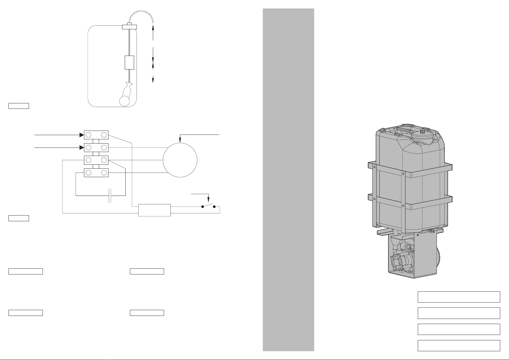
• Togliere dalla tanica il tappo comprensivo di livellostato (4).
• Regolare la posizione del livellostato e del peso, come indicato in Fig. 3.
• Togliere la tanica dalla gabbia metallica (Fig. 2) sganciando il raccordo idraulico
maschio/femmina (5).
• Aprire il coperchio sulla scatola del motore (3).
• Collegare l’alimentazione come indicato in Fig. 4.
• Richiudere il coperchio.
• Riempire di acqua la tanica e inserirla nella gabbia metallica facendo attenzione di
eseguire correttamente l’inserzione del raccordo idraulico maschio/femmina (5).
• Assicurarsi che dal raccordo di mandata della pompa (6) esca una piccola quantità
di acqua.
• Collegare il tubo di mandata.
• Il sistema è pronto per essere alimentato.
ITALIANO ENGLISH
FRANCAIS DEUTSCH
INSTALLATION:
Turn off the power before performing any kind of operations.
Add to the water antifreezing liquid, like the one used for car, if
temperature lower than 3°C / 37°F.
Ꮨ
It is necessary to insert a monopolar 1 0 switch (open contact
distance d>3 mm) upstream of the appliance. This switch should be
used to disconnect the power supply before carrying out any
maintenance or opening the appliance.
The device is provided with its installed accessories.
• Fix, in reliably way, the metal cage (1) to a wall by the 4 holes (2) suitably
arranged (Fig. 1).
• Take away the cover comprehensive of level switch from the tank (4).
• Set the level switch and weight position, as shown in Fig. 3.
• Take away the tank from the metal cage (Fig. 2) unhooking the plumber
connector male/female (5).
• Open the cover on the box of the motor (3).
• Connect the power supply as shown in Fig. 4.
• Close the cover.
• Fill the tank with water and insert it in the metal cage paying attention
to execute the insertion of the plumber connector male/female (5)
correctly.
• To be sure what from the connector of sent of the pump (6) a little amount of
water goes out.
• Connect the delivery pipe.
• The system is ready to be powered.
INSTALLATION:
Avant d’effectuer toute opération, il est indispensable de couper
l'alimentation.
Ajouter à l‘eau du liquide antigel, du type pour voiture, en cas
d’utilisation avec température inférieure à 3°C.
Ꮨ
Insérer un interrupteur général unipolaire 1 0 sur la ligne
d'alimentation en amont de l'appareil (distance ouverture des contacts
d>3 mm). Cet interrupteur doit être utilisé pour séparer l'alimentation
avant toute opération d'entretien et toute ouverture de l'appareil.
L’unité est fournie avec ses accessoires montés
• Fixer solidement la cage métallique (1) à la surface au moyen des 4 trous (2) de
fixation (Fig. 1).
• Enlever du réservoir le bouchon avec l’indicateur de niveau (4).
• Régler la position de l’indicateur de niveau et du pois, comme indiqué en
Fig. 3.
• Enlever le réservoir de la cage métallique (Fig. 2), en décrochant le raccord
hydraulique mâle/femelle (5).
• Ouvrir le couvercle de la boîte du moteur (3).
• Raccorder l’alimentation comme indiqué en Fig. 4.
• Fermer le couvercle.
• Remplir d’eau le réservoir et le replacer dans la cage métallique, en faisant
attention d’insérer correctement le raccord hydraulique mâle/femelle (5).
• S’assurer qu’une petite quantité d’eau sort du raccord de refoulement de la
pompe (6).
• Raccorder le tube de refoulement.
• Le système est prêt pour la mise en marche.
INSTALLATION:
Vor allen Eingriffen immer den Netzstecker aus der Steckdose ziehen.
Mit -3°C- Temperatur die Frostschutzflüssigkeit, als die für Auto
benutzt, am Wasser zusammeneinfügen
Ꮨ
Auf der Versorgungsleitung muß ein einpoliger Hauptschalter 1 0
vorgeschaltet werden (Unterbrecherkontaktabstand d>3 mm). Dieser
Schalter ist als Trennvorrichtung zum Abnehmen der Stromversorgung
einzusetzen, bevor Wartungsarbeiten durchgeführt werden oder das
Gerät geöffnet wird.
Diese Vorrichtung wird mit dem folgenden, vorinstallierten Zubehör geliefert:
• Den Metallkäfig (1) mit Hilfe der 4 bereits (2) vorhandenen Löcher den
Metallkäfig an einer Wand befestigen (Fig. 1).
• Den Verschluß einschließlich Wasserstandsregler entfernen (4).
• Den Wasserstandsregler und das Gewicht so positionieren, wie es in Fig. 3 gezeigt wird.
• Den Kanister vom Metallkäfig entfernen (Fig. 2), indem die Hydraulikverbindung
aus Vater- und Mutterteil (5) gelöst wird.
• Die Abdeckung über dem Motorgehäuse öffnen (3).
• Die Versorgung nach Fig. 4 herstellen.
• Die Abdeckung wieder schließen.
• Den Kanister mit Wasser füllen und in den Metallkäfig einlegen. Achten Sie
darauf, daß die Hydraulikverbindung zwischen Vater- und Mutterteil (5) korrekt
hergestellt wird.
• Überzeugen Sie sich, daß aus dem Druckanschluß der Pumpe (6) eine geringe
Wassermenge austritt.
• Die Druckleitung anschließen.
• Das System kann nun gespeist werden.
SPECIFICHE TECNICHE:
-Materiale:
Tanica in polietilene
Gabbia in acciaio inox
-Dimensioni esterne:
710x300x270 mm
-Temperatura d’esercizio:
Da +3°C a +50°C
-Peso:
12.4 kg
-Alimentazione:
230VAC, 50 Hz, 600 W
-Grado di protezione:
IP45
-Prevalenza:
30 m
ITALIANO ENGLISH
FRANCAIS DEUTSCH
TECHNICAL SPECIFICATIONS:
-Materials:
Polyethylene Tank
Stainless steel cage
-External dimensions:
710x300x270 mm / 28x12x11 in
-Working temperature:
From +3°C to +50°C / from +37°F to +122°F
-Weight:
12.4 kg / 27.3 lb
-Power supply:
230VAC, 50 Hz, 600 W
-Protection rating:
IP45
-Delivery:
30 m / 98 ft
SPÉCIFICATIONS TECHNIQUES:
-Matériel:
Réservoir en polyéthylène
Cage en acier inox
-Dimensions externes:
710x300x270 mm
-Température d'utilisation:
De +3°C à +50°C
-Poids:
12.4 kg
-Alimentation:
230VAC, 50 Hz, 600 W
-Degré de protection:
IP45
-Hauteur d’élévation:
30 m
TECHNISCHE DATEN:
-Werkstoff:
Polyäthylentank
Rostfreibehälter
-Außenabmessungen:
710x300x270 mm
-Gebrauchstemperatur:
Von +3°C bis +50°C
-Gewicht:
12.4 kg
-Spannungsversorgung:
230VAC, 50 Hz, 600 W
-Schutzart:
IP45
-Förderhöhe:
30 m