Videotec Wasex User manual

ENGLISH ITALIANO FRANÇAIS DEUTSCH
РУССКИЙ
EN
English - Instructions manual
IT
Italiano - Manuale di istruzioni
FR
Français - Manuel d’instructions
DE
Deutsch - Bedienungslanleitung
RU
- Руководство по эксплуатации
WASEX
Stainless steel washer pump with explosion-
proof solenoid valve for MAXIMUS series


Instructions manual - English - EN
1MNVKWASEX_1511_EN
ENGLISH
WASEX
Stainless steel water tank with explosion-proof solenoid valve for MAXIMUS
series
1 About this manual
Before installing and using this unit, please read this
manual carefully. Be sure to keep it handy for later
reference.
1.1 Typographical conventions
DANGER!
Explosion hazard.
Read carefully to avoid danger of explosion.
DANGER!
High level hazard.
Risk of electric shock. Disconnect the
power supply before proceeding with any
operation, unless indicated otherwise.
CAUTION!
Medium level hazard.
This operation is very important for the
system to function properly. Please read
the procedure described very carefully and
carry it out as instructed.
INFO
Description of system specications.
We recommend reading this part carefully
in order to understand the subsequent
stages.
2 Notes on copyright and
information on trademarks
The quoted names of products or companies are
trademarks or registered trademarks.
3 Safety rules
CAUTION! The electrical system to which
the unit is connected must be equipped
with a 15A max automatic bipolar circuit
breaker. The minimum distance between
the contacts must be 3mm (0.1in). The
circuit breaker must be provided with
protection against the fault current
towards the ground (dierential) and the
overcurrent (magnetothermal).
CAUTION! The device must be installed
only and exclusively by skilled technical
personnel.
This device must be connected to the
ground as shown in gure.
Fig. 1
• Read these instructions.
• Keep these instructions.
• Heed all warnings.
• Follow all instructions.
• Make sure that all the devices are suitable for the
application and for the environment in which they
will be installed.
• Make sure that the connected devices are
completely compatible and suitable for use.
• Make sure the operating temperatures are
compatible with the devices.

EN - English - Instructions manual
2 MNVKWASEX_1511_EN
• The manufacturer declines all responsibility
for any damage caused by an improper use
of the appliances mentioned in this manual.
Furthermore, the manufacturer reserves the right
to modify its contents without any prior notice.
The documentation contained in this manual has
been collected with great care. The manufacturer,
however, cannot take any liability for its use. The
same thing can be said for any person or company
involved in the creation and production of this
manual.
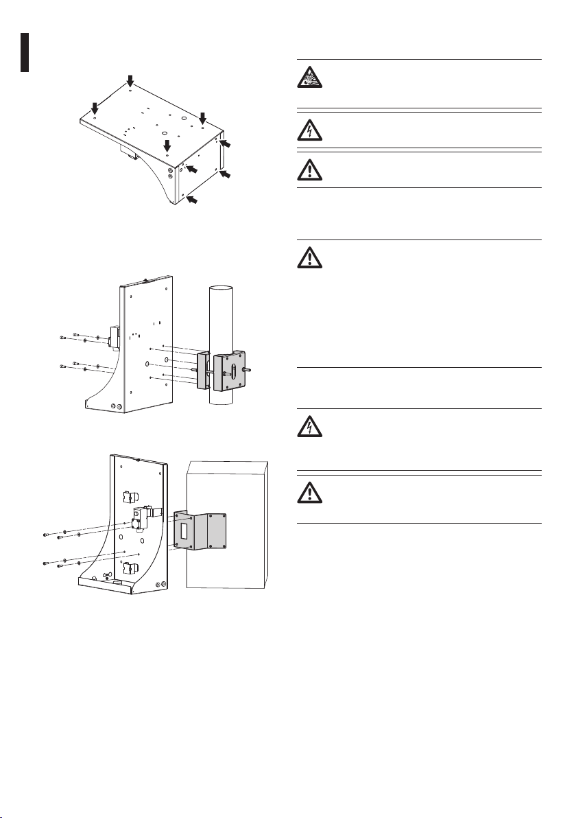
• When installing the devices make sure the system
and installer personnel are absolutely safe.
• Choose an installation site that is strong enough
to sustain the weight of the device, also bearing
in mind particular environmental aspects, such as
exposure to strong winds.
• We strongly recommend using only approved
brackets and accessories during installation.
• Make sure that the device is rmly anchored so
that it cannot become detached.
• Since the user is responsible for choosing the
surface to which the device is to be anchored,
we do not supply screws for attaching the device
rmly to the particular surface. The installer is
responsible for choosing screws suitable for the
specic purpose on hand.
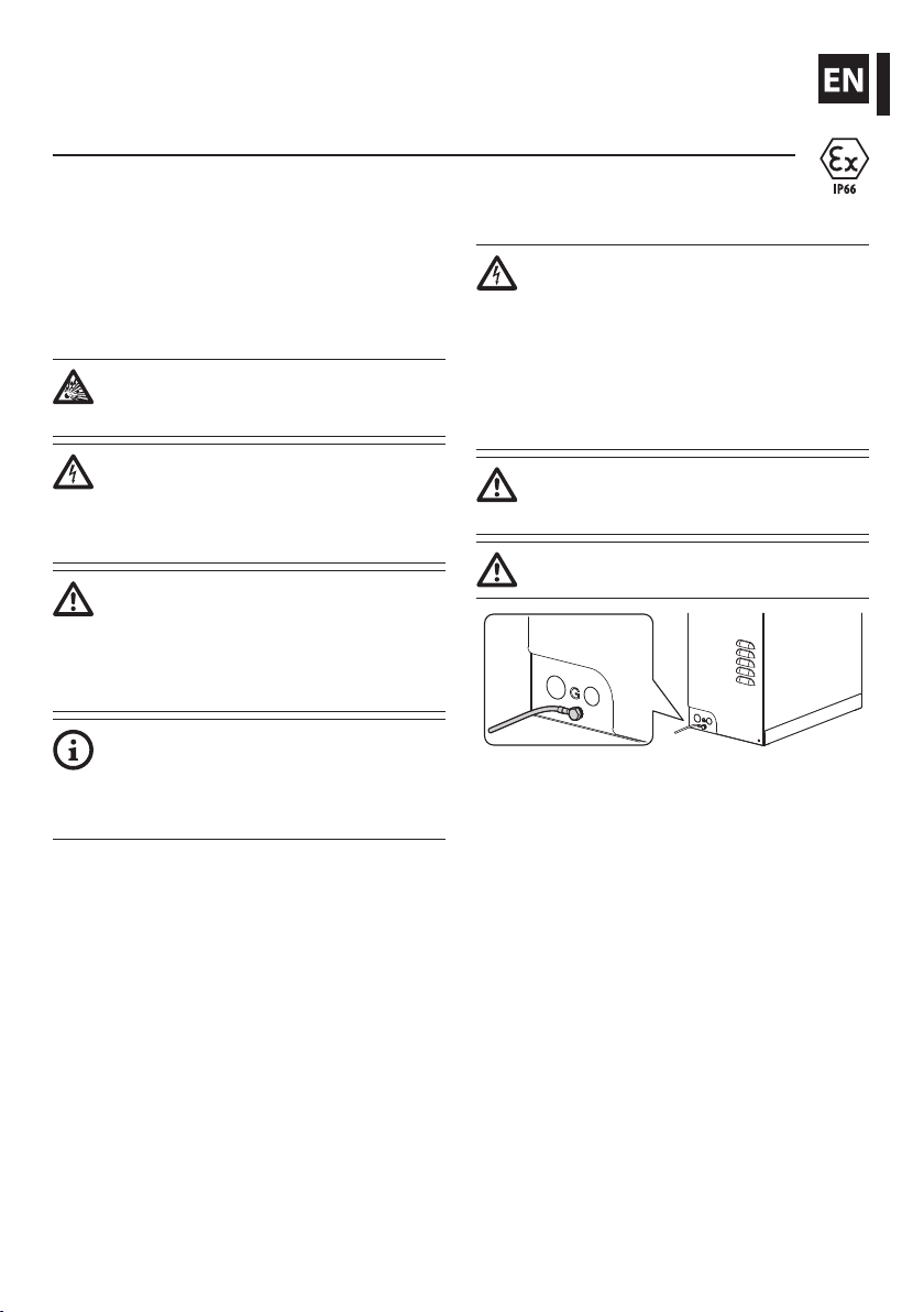
• Before starting any operation, make sure the
power supply is disconnected.
• Do not use cables that seem worn or old.
• Only qualied technical personnel should be
allowed to open the device, and they should work
in a non-explosive atmosphere. Tampering with
the device will invalidate the guarantee.
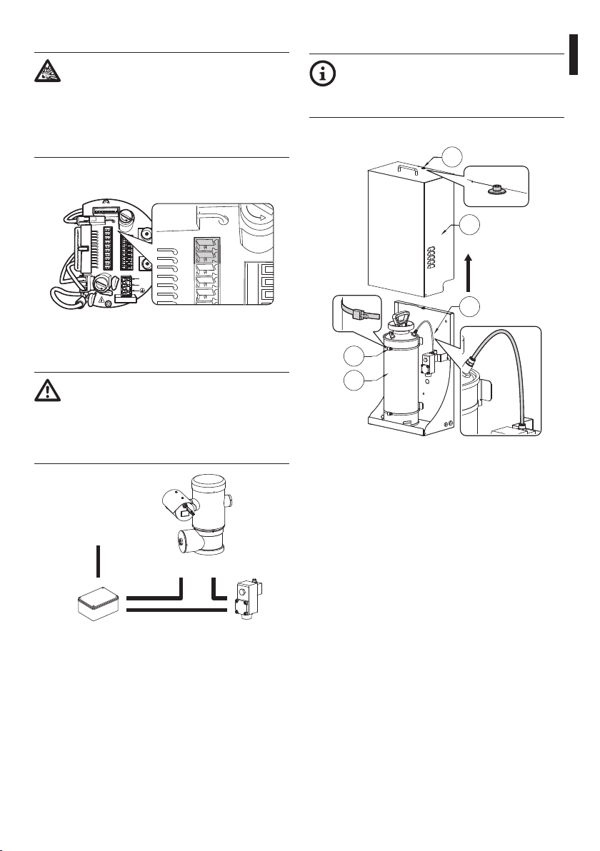
• The device can only be considered to be switched
o when the power supply has been disconnected
and the connection cables to other devices have
been removed.
• Before powering the device install an overload
protection device in the electrical equipment for
the building.
• For technical services, consult only and exclusively
authorized technicians.
• Keep this handbook carefully; it must be available
for consultation on the installation site.
• Never, under any circumstances, make any
changes or connections that are not shown in
this handbook. Improper use of the appliance
can cause serious hazards, risking the safety of
personnel and of the installation.
• Use only VIDEOTEC original spare parts.
• Before proceeding with installation, check the
supplied material to make sure it corresponds
to the order specication by examining the
identication labels (4.2 Product markings, page 3).

Instructions manual - English - EN
3MNVKWASEX_1511_EN
4 Identication
4.1 Product description and type
designation
The WASEX washer pump is built with a stainless
steel AISI 316L enclosure which guarantees excellent
corrosion resistance both in industrial and seaside
areas.
The system guarantees complete cleaning of glass on
the MAXIMUS devices.
The articulated nozzle of the pump can be adjusted
in order to associate to a preset, in the desired
position, the wiper and spray functions.
The pump is controlled by an explosion-proof
solenoid valve which provides liquid passage and
by the MAXIMUS pan & tilt telemetry or by a manual
electric contact.
The tank has a 10 litre capacity and can be lled
with an integrated hand pump or by means of other
devices depending on the user's requirements.
The system is available in 24Vac/dc.
The solenoid valve (01) has a hole for a ½” NPT cable
gland (02).
02
01
Fig. 2
The cable glands must be selected according to what
is indicated by the EN/IEC 60079-14 Standard.
These cable glands guarantee an IP66 protection
level.
We recommend using VIDEOTEC cable
glands or equivalent (Tab. 2, page11).
4.2 Product markings
The marking on the glass washer pump relates to the
marking on the solenoid valve. The marking plate is
tted on the solenoid valve.
Fig. 3
The product serial number is indicated in the label
positioned as shown in the gure.
Fig. 4

EN - English - Instructions manual
4 MNVKWASEX_1511_EN
5 Preparing the product for
use
Any change that is not expressly approved
by the manufacturer will invalidate the
guarantee.
No special requirements are demanded
from those in charge of handling; therefore
follow normal accident prevention
regulations when carrying out this
operation.
5.1 Safety precautions before use
Never exceed performance specications.
Make all connections in a non-explosive
atmosphere.
Before starting any operation, make sure
the power supply is disconnected.
The assembly and installation must be
performed only by skilled personnel.
Make connections and tests in the
laboratory before carrying out installation
on site. Use appropriate tools for the
purpose.
5.2 Unpacking and contents
5.2.1 Unpacking
When the product is delivered, make sure that the
package is intact and that there are no signs that it
has been dropped or scratched.
If there are obvious signs of damage, contact the
supplier immediately.
Keep the packaging in case you need to send the
product for repairs.
Unscrew the 2 side screws to open the
cover.
Fig. 5
5.2.2 Contents
Check the contents to make sure they correspond
with the list of materials as below:
• Washer kit
• Washer pipe support
• Locking bracket for pipe support
• Screws and washers
• Washer pipe (with nozzle)
• Pipe connector
• Stainless steel clamps
• Delivery pipe
• Sealing rings
• Instructions manual
• Solenoid valve user and installation manual

Instructions manual - English - EN
5MNVKWASEX_1511_EN
5.3 Safely disposing of packaging
material
The packaging material can all be recycled. The
installer technician will be responsible for separating
the material for disposal, and in any case for
compliance with the legislation in force where the
device is to be used.
When returning a faulty product we recommend
using the original packaging for shipping.
5.4 Preparatory work before
installation
5.4.1 Drilling the box (optional)
The product has 2 holes with seal rings for passing
through the power cord of the solenoid valve and
the delivery pipe. In order to assemble additional seal
rings, it is possible to create other holes on the base
and left-hand side.
Fig. 6
5.4.2 Assembly of the seal rings
(optional)
During assembly, be careful not to damage
the rubber and thereby reduce its air-
tightness.
Position the sealing ring against the hole. Grip the
sealing ring from the outside using pliers or a similar
tool. Pull it through the hole until the conical part
has come all the way out. The seal ring should adhere
fully to the hole in its nal position.
Fig. 7
Limits of the cable port hole and the used cables
diameters.
LIMITATIONS OF USE RELATING TOTHE DIAMETER OF
THE HOLE AND OF THE CABLES
Sealing ring Ø Cable port
hole (mm/in)
Cable Ø limits
(mm/in)
M16 16.5 5-9
M20 20.5 8-12
Tab. 1

EN - English - Instructions manual
6 MNVKWASEX_1511_EN
5.4.3 Assembly on supports
There are holes in the box for wall or oor mounting.
Fig. 8
The box can be also mounted on the pole mount
adapter or the corner adaptor .
Fig. 9WASEX+NXCOL.
Fig. 10 WASEX+NXCW.
6 Assembling and installing
Never exceed performance specications.
Make all connections in a non-explosive
atmosphere.
Before starting any operation, make sure
the power supply is disconnected.
The assembly and installation must be
performed only by skilled personnel.
6.1 Installation
6.1.1 Installing the pump tank
We recommend lling the tank with water
at room temperature. If using the pump at
temperatures below 3°C (37.4°F) add some
glass cleaner antifreeze liquid to the water.
The liquid used must have an ignition
temperature (IEC 60079-4) at least 50K
above the maximum surface temperature
of the equipment. The liquid used must not
cause ignition of the atmosphere.
6.1.2 Connection of the power supply
line
When commencing installation make sure
that the specications for the power supply
for the installation correspond with those
required by the device.
Make sure that the power source and
connecting cables are suitable for the
power consumption of the system.
6.1.2.1 Connection of the solenoid valve
Connect the solenoid valve. For further information,
refer to the product use and installation manual.

Instructions manual - English - EN
7MNVKWASEX_1511_EN
6.1.2.2 Connection to the pan & tilt
The electric connections between the
solenoid valve and P&T must be housed
in an explosion-proof junction box.
The explosion-proof junction box must
be suitable for the classication of the
explosive atmosphere in the installation
site, according to the regulations in force.
Use the RL2 (J3) internal relay to connect to the pan &
tilt, if necessary.
F
U
S
E
F
U
S
E
100nMBW3
L
N
VAR3
VAR1
AC
AL1
AL2
AL3
AL4
AL5
COM
RL1
RL1
RL2
RL2
GND
W
GND
B
A
B
A
IN
J1
J9
J6
J2
J3
J8
J4
J7
FUS1
VAR2
VIDEO - 1
VIDEO - 2
RS485
ADDRESS & PROTOCOL
FUS2
COM
RL1
RL1
RL2
RL2
J2
J3
J8
FUS2
Fig. 11
Connect and power the solenoid valve with reference
to the connection diagram. (Fig. 12, page7).
The RL2 relay in the pan & tilt can withstand
a voltage of up to 30Vac. Use only 24Vac
models of solenoid valve powered by safety
transformer Turn o one of the supply
poles of the solenoid valve via the RL2 relay
of the pan & tilt.
RL2 RL2
Safety transformer
24Vac power supply
Explosion-proof jun-
ction box
Solenoid valve
Fig. 12
6.1.3 Installation of the pump
It is possible to install or service the pump
without removing the tank. To remove the
tank (01), release the metal clamps (02) and
disconnect the connecting pipe (03).
Undo the safety screw (04) and lift the guard (05).
05
03
04
02
01
Fig. 13

EN - English - Instructions manual
8 MNVKWASEX_1511_EN
Turn the safety valve to release any residual pressure
in the tank.
Fig. 14
Undo the top body of the pump (01) by turning it
anti-clockwise and removing it. Fill the tank (02) (10l
max) Re-install the top body of the pump.
01
02
Fig. 15
Pressurize the tank by pumping the top body of the
pump up to a pressure of 3.5Bar. Turn the handle on
the body of the pump to its safety position.
Fig. 16
Connect the delivery pipe (01), passing it through the
seal ring (02).
01
02
Fig. 17
Insert the guard and tighten the safety screw.
Fig. 18
6.1.4 Washer installation (pan & tilt)
Fasten the bracket (01) onto the body of the pan & tilt
with the metal clamp (02) provided.
02
01
Fig. 19

Instructions manual - English - EN
9MNVKWASEX_1511_EN
Shorten the washer pipe (01) as needed. Unscrew the
nut (02) and slide it along the pipe. Insert the end of
the pipe into the ogive (03).
03
01
02
Fig. 20
Lock the nut to the coupling.
Fig. 21
Attach the pipe to the washer support using the
bracket (01), the screws (02) and the washers (03)
supplied. Connect the supply pipe (04).
02
03
01
04
Fig. 22
To calibrate the jet direct the nozzle towards the glass
of the housing.
Fig. 23
To start the washer, refer to the pan & tilt manual.
6.1.4.1 Installation examples
Fig. 24
Fig. 25
Fig. 26 Pipe attached to the wall with a plate.

EN - English - Instructions manual
10 MNVKWASEX_1511_EN
7 Maintaining and cleaning
Before doing any technical work or
maintenance on the device, make sure that
potentially explosive atmosphere is not
present.
Before doing any technical work on the
device, disconnect the power supply.
7.1 Maintaining
Maintenance must be carried out by
personnel trained to operate on electrical
circuits.
7.1.1 Routine (to be carried out
regularly)
7.1.1.1 Filling the tank
Fill the tank with reference to the pump installation
procedure (6.1.3 Installation of the pump, page7).
7.1.1.2 Cleaning the device
This should be done regularly. If a layer of dust
accumulates on the outside of the housing, it should
never be more than 5mm thick. The device should be
cleaned using a damp cloth; compressed air must not
be used. Maintenance frequency will depend on the
type of environment in which the housing is used.
7.1.1.3 Inspecting the cables
The cables should not show signs of damage or wear,
which could generate hazardous situations. In this
case extraordinary maintenance is necessary.
7.1.2 Extraordinary (to be done only
under particular circumstances)
Replacing the solenoid valve
Fig. 27
Whenever replacing the parts as indicated,
always use VIDEOTEC original.
The manufacturer declines all liability for
damage to any of the apparatus mentioned
in this handbook, when resulting from
tampering, use of non-original spare parts,
and from installation and maintenance/
repairs performed by non-authorised, non-
skilled personnel.
7.1.3 Spare parts
To order the spare parts it is necessary to
provide the serial number of the product on
which the intervention is to be carried out.
8 Disposal of waste
materials
This symbol mark and recycle system
are applied only to EU countries and not
applied to the countries in the other area of
the world.
Your product is designed and manufactured with
high quality materials and components which can be
recycled and reused.
This symbol means that electrical and electronic
equipment, at their end-of-life, should be disposed of
separately from your household waste.
Please dispose of this equipment at your local
Community waste collection or Recycling centre.
In the European Union there are separate collection
systems for used electrical and electronic products.

Instructions manual - English - EN
11MNVKWASEX_1511_EN
9 Technical data
9.1 General
Enclosure made of stainless steel AISI 316L
Water tank capacity: 10l (2.6gal)
Pipe material: Antistatic plastic
9.2 Mechanical
Pressure: 4bar
Delivery head: 20m (66ft)
Dimensions (WxHxL): 429x697x255mm
(16.9x27.4x10in)
Unit weight: 18kg (40lb)
9.3 Electrical
Power supply: 24Vac/dc, 50/60Hz
Consumption: 5W
9.4 Environment
Indoor/Outdoor
Operating temperature: From -40°C (-40°F) up to
+60°C (140°F)
9.5 Certications
EAC EX
Ex d IIC T4
Solenoid valve:
ATEX (EN 60079-0: 2009, EN 60079-1: 2007, EN 60079-
31: 2009)
bII GD Ex d IIC T4 Gb
Ex tb IIIC T130°C Db IP66
Tamb -40/+60°C (-40°F / +140°F)
INMETRO
Ex d IIC T4 Gb IP66
Tamb -40/+60°C (-40°F / +140°F)
9.6 Cable glands
1/2" NPT CABLE GLAND SELECTION LAYOUT
Zone, Gas Cable gland
type
Certication Operating
temperature
Cable Cable glands
part code
Diameter of
the external
cable (mm)
IIC, Zone 1 or
Zone 2
IIB or IIA, Zone 1
Barrier IECEX/ATEX/
EAC
-60 / +80°C
(-76°F / +176°F)
Not armored OCTEXB1/2C 3 - 8
IIB or IIA, Zone 2 With gasket IECEX/ATEX/
EAC
-60 / +100°C
(-76°F / +212°F)
Not armored OCTEX1/2C 3 - 8
Not armored OCTEXS1/2C 7.5 - 11.9
Tab. 2

MNVKWASEX_1511_EN
10 Technical drawings
The dimensions of the drawings are in millimetres.
WASEX+NXCOL WASEX+NXCW
280
210
429
40 30
662
697
255300
500
Ø 11
32
Ø 11
Fig. 28 WASEX.
Headquarters Italy Videotec S.p.A.
Via Friuli, 6 - I-36015 Schio (VI) - Italy
Tel. +39 0445 697411 - Fax +39 0445 697414
Email: [email protected]
www.videotec.com

Manuale di istruzioni - Italiano - IT
1MNVKWASEX_1511_IT
ITALIANO
WASEX
Tanica lavavetro con elettrovalvola antideagrante in acciaio inox per serie
MAXIMUS
1 Informazioni sul presente
manuale
Prima di installare e utilizzare questa unità, leggere
attentamente questo manuale. Conservare questo
manuale a portata di mano come riferimento futuro.
1.1 Convenzioni tipograche
PERICOLO!
Pericolo di esplosione.
Leggere attentamente per evitare pericoli
di esplosione.
PERICOLO!
Pericolosità elevata.
Rischio di scosse elettriche. Prima di
eseguire qualsiasi operazione assicurarsi di
togliere tensione al prodotto, salvo diversa
indicazione.
ATTENZIONE!
Pericolosità media.
L'operazione è molto importante per il
corretto funzionamento del sistema. Si
prega di leggere attentamente la procedura
indicata e di eseguirla secondo le modalità
previste.
INFO
Descrizione delle caratteristiche del
sistema.
Si consiglia di leggere attentamente per
comprendere le fasi successive.
2 Note sul copyright e
informazioni sui marchi
commerciali
I nomi di prodotto o di aziende citati sono marchi
commerciali o marchi commerciali registrati
appartenenti alle rispettive società.
3 Norme di sicurezza
ATTENZIONE! L’impianto elettrico al quale
è collegata l’unità deve essere dotato di
un interruttore di protezione bipolare
automatico da 15A max. La distanza
minima tra i contatti deve essere di 3mm.
L’interruttore deve essere provvisto di
protezione contro la corrente di guasto
verso terra (dierenziale) e la sovracorrente
(magnetotermico).
ATTENZIONE! L'installazione e la
manutenzione del dispositivo deve
essere eseguita solo da personale tecnico
qualicato.
Questo dispositivo deve essere collegato a
terra come illustrato in gura.
Fig. 1
• Leggere le istruzioni.
• Conservare le istruzioni.
• Osservare tutte le avvertenze.
• Attenersi a tutte le istruzioni.
• Assicurarsi che tutti i dispositivi siano adatti per
l’applicazione e l’ambiente per cui sono stati
progettati.
• Assicurarsi che i dispositivi collegati siano
completamente compatibili e adatti all’uso.
• Controllare che le temperature di esercizio siano
compatibili con i dispositivi.

IT - Italiano - Manuale di istruzioni
2 MNVKWASEX_1511_IT
• Il produttore declina ogni responsabilità per
eventuali danni derivanti da un uso improprio
delle apparecchiature menzionate in questo
manuale. Si riserva inoltre il diritto di modicarne il
contenuto senza preavviso. Ogni cura è stata posta
nella raccolta e nella verica della documentazione
contenuta in questo manuale. Il produttore,
tuttavia, non può assumersi alcuna responsabilità
derivante dall'utilizzo della stessa. Lo stesso
dicasi per ogni persona o società coinvolta nella
creazione e nella produzione di questo manuale.
• Accertarsi di installare i dispositivi in maniera
tale da garantire la sicurezza dell’impianto e del
personale addetto all’installazione.
• Scegliere la postazione di installazione in modo
che sia sucientemente solida da sostenere il
peso del dispositivo, considerando anche aspetti
ambientali particolari come esposizione a vento
forte.
• Si raccomanda di utilizzare solo stae o accessori
consigliate per l’installazione.
• Accertarsi che il dispositivo sia ssato in maniera
solida ed adabile.
• Dato che la scelta della supercie di montaggio
è a cura dell’utente non si forniscono viti per il
ssaggio sicuro del dispositivo alla supercie. È
responsabilità dell’installatore utilizzare viti adatte
allo scopo specico richiesto.
• Prima di eseguire qualsiasi operazione assicurarsi
di togliere tensione al prodotto.
• Non utilizzare cavi con segni di usura o
invecchiamento.
• L’apparecchio deve essere aperto soltanto da
personale tecnico qualicato e in atmosfera non
esplosiva. La manomissione dell’apparecchio fa
decadere i termini di garanzia.
• L’apparecchio si considera disattivato soltanto
quando l’alimentazione è disinserita e i cavi di
collegamento con altri dispositivi sono stati
rimossi.
• Prima dell’alimentazione del dispositivo installare
un dispositivo di protezione nell’impianto elettrico
dell’edicio.
• Per l’assistenza tecnica rivolgersi esclusivamente al
personale tecnico autorizzato.
• Conservare con cura il presente manuale; deve
essere a disposizione per eventuali consultazioni
nel luogo in cui viene eseguita l’installazione.
• Non eettuare per nessun motivo alterazioni o
collegamenti non previsti in questo manuale.
L'uso di apparecchi non idonei può portare a
gravi pericoli per la sicurezza del personale e
dell'impianto.
• Utilizzare solo parti di ricambio VIDEOTEC.
• Prima di procedere con l'installazione, controllare
che il materiale fornito corrisponda alle speciche
richieste esaminando le etichette di marcatura (4.2
Marcatura del prodotto, pagina 3).

Manuale di istruzioni - Italiano - IT
3MNVKWASEX_1511_IT
4 Identicazione
4.1 Descrizione e designazione
del prodotto
La pompa lavavetro WASEX è costruita con la cassetta
esterna in acciaio inox AISI 316L la quale garantisce
un’ottima resistenza alla corrosione sia negli ambienti
industriali che marini.
Il sistema garantisce una completa pulizia dei vetri sui
dispositivi MAXIMUS.
È possibile regolare l’ugello snodabile della pompa
per poter associare a un preset, nella posizione
desiderata, le funzioni di tergicristallo e spruzzo.
La pompa è comandata da un’elettrovalvola
antideagrante che permette il passaggio del liquido
ed è comandata dalla telemetria del brandeggio
MAXIMUS oppure tramite un contatto elettrico
manuale.
Il serbatoio ha una capacità di 10 litri e può essere
caricato tramite una pompa manuale integrata
oppure tramite altri dispositivi a seconda delle
esigenze dell’utilizzatore.
Il sistema è disponibile in 24Vac/dc.
L'elettrovalvola (01) presenta un foro per pressacavo
1/2" NPT (02).
02
01
Fig. 2
La scelta del pressacavo deve essere fatta secondo
quanto previsto dalla norma EN/IEC 60079-14.
Tali pressacavi assicureranno il grado di protezione
IP66.
Si consiglia l'utilizzo di pressacavi
VIDEOTEC o equivalenti (Tab. 2, pagina11).
4.2 Marcatura del prodotto
La marcatura della pompa lavavetro è denita
dalla marcatura dell'elettrovalvola. La targhetta di
marcatura è posta sull'elettrovalvola stessa.
Fig. 3
Il numero di serie del prodotto è indicato
nell'etichetta posizionata come in gura.
Fig. 4

IT - Italiano - Manuale di istruzioni
4 MNVKWASEX_1511_IT
5 Preparazione del prodotto
per l'utilizzo
Qualsiasi cambiamento non espressamente
approvato dal costruttore fa decadere la
garanzia.
Per la movimentazione non sono richiesti
particolari requisiti da parte del personale
addetto, pertanto, si raccomanda di
eettuare tale operazione osservando le
comuni norme di antinfortunistica.
5.1 Precauzioni di sicurezza
prima dell'utilizzo
Non superare le prestazioni specicate.
Eseguire tutte le connessioni in atmosfera
non esplosiva.
Prima di eseguire qualsiasi operazione
ricordarsi di togliere tensione al prodotto.
L'assemblaggio e l'installazione vanno
eseguiti solo da personale qualicato.
Eettuare i collegamenti e prove in
laboratorio prima dell’installazione nel sito.
Utilizzare degli utensili adeguati.
5.2 Disimballaggio e contenuto
5.2.1 Disimballaggio
Alla consegna del prodotto vericare che l'imballo
sia integro e non abbia segni evidenti di cadute o
abrasioni.
In caso di evidenti segni di danno all'imballo
contattare immediatamente il fornitore.
Conservare l'imballo nel caso sia necessario inviare il
prodotto in riparazione.
Per aprire il coperchio svitare le 2 viti
laterali.
Fig. 5
5.2.2 Contenuto
Controllare che il contenuto sia corrispondente alla
lista del materiale sotto elencata:
• Kit lavavetro
• Sostegno tubo lavavetro
• Staa bloccaggio tubo lavavetro
• Viti e rondelle
• Tubo lavavetro (completo di ugello)
• Raccordo per tubo
• Fascette inox
• Tubo di mandata
• Anelli di tenuta
• Manuale di istruzioni
• Manuale d'uso ed installazione dell'elettrovalvola

Manuale di istruzioni - Italiano - IT
5MNVKWASEX_1511_IT
5.3 Smaltimento in sicurezza dei
materiali di imballaggio
I materiali d'imballo sono costituiti interamente da
materiale riciclabile. Sarà cura del tecnico installatore
smaltirli secondo le modalità di raccolta dierenziata
o comunque secondo le norme vigenti nel Paese di
utilizzo.
In caso di restituzione del prodotto malfunzionante
è consigliato l'utilizzo dell'imballaggio originale per
il trasporto.
5.4 Lavoro preparatorio prima
dell’installazione
5.4.1 Foratura della scatola (opzionale)
Il prodotto è fornito con 2 fori muniti di anelli di
tenuta per il passaggio del cavo di alimentazione
dell'elettrovalvola e del tubo di mandata. Per il
montaggio di ulteriori anelli di tenuta, in alternativa,
possono essere aperti altri fori sul fondo e sul lato
sinistro.
Fig. 6
5.4.2 Montaggio degli anelli di tenuta
(opzionale)
Durante il montaggio è necessario prestare
attenzione a non danneggiare la gomma
per non comprometterne l’impermeabilità.
Posizionare l'anello di tenuta in corrispondenza del
foro. Aerrare l’anello di tenuta dall’esterno con una
pinza o un attrezzo simile. Tirarlo facendolo passare
attraverso il foro no all’uscita completa della parte
conica. L'anello di tenuta in posizione nale dovrà
aderire completamente al foro di passaggio.
Fig. 7
Limiti di utilizzo del diametro del foro di passaggio e
del diametro dei cavi utilizzati.
LIMITI D’UTILIZZO DEL DIAMETRO DEL FORO DI
PASSAGGIO E DEL DIAMETRO DEI CAVI UTILIZZATI
Anello di tenuta Ø foro di passag-
gio (mm)
Limiti Ø cavo
(mm)
M16 16.5 5-9
M20 20.5 8-12
Tab. 1

IT - Italiano - Manuale di istruzioni
6 MNVKWASEX_1511_IT
5.4.3 Montaggio sui supporti
La scatola può essere ssata direttamente a parete o
a pavimento utilizzando i fori presenti.
Fig. 8
La scatola può essere montata anche su collare da
palo o adattatore angolare.
Fig. 9WASEX+NXCOL.
Fig. 10 WASEX+NXCW.
6 Assemblaggio e
installazione
Non superare le prestazioni specicate.
Eseguire tutte le connessioni in atmosfera
non esplosiva.
Prima di eseguire qualsiasi operazione
ricordarsi di togliere tensione al prodotto.
L'assemblaggio e l'installazione vanno
eseguiti solo da personale qualicato.
6.1 Installazione
6.1.1 Installazione del serbatoio della
pompa
Si raccomanda di riempire il serbatoio con
acqua a temperatura ambiente. Nel caso
di utilizzo a temperature inferiori a 3°C
aggiungere all’acqua del liquido antigelo
per lavavetri. Il liquido utilizzato deve avere
una temperatura di accensione (IEC 60079-
4) di almeno 50K oltre la temperatura
massima di supercie dell'apparecchiatura.
Il liquido utilizzato non deve causare
accensioni dell'atmosfera.
6.1.2 Collegamento della linea di
alimentazione
All’atto dell’installazione controllare che
le caratteristiche di alimentazione fornite
dall’impianto corrispondano a quelle
richieste dal dispositivo.
Controllare che le fonti di alimentazione
ed i cavi di collegamento siano in grado di
sopportare il consumo del sistema.
6.1.2.1 Collegamento dell'elettrovalvola
Collegare l'elettrovalvola. Fare riferimento al manuale
d’uso ed installazione del prodotto per ulteriori
informazioni.
Table of contents
Languages:
Other Videotec Water Pump manuals
Popular Water Pump manuals by other brands

Graco
Graco Check-Mate 2100 Instructions-parts list

Pentair
Pentair AURORA 3310 INSTRUCTION, INSTALLATION, MAINTENANCE AND REPAIR MANUAL

Grundfos
Grundfos KPC Series Installation and operating instructions

Kodiak
Kodiak PSP125ABK Installation, operation & maintenance manual

HEISSNER
HEISSNER HFP10000-00 Instructions for use

Spowdi
Spowdi Pro MKII installation manual