Videx 380N/UK Assembly instructions

ART. 380N/UK
Telephone Interface Module
66250010-EN
V2.0 - 24/09/18
We recommend
This equipment is installed by a
Competent Electrician, Security or
Communications Engineer.
Installation and
Programming Manual
ENG

66250010-EN - V2.0 - 24/09/18
THE POWER TO SECURE
- 2 -
Art. 380N/UK Telephone Interface Module - Installation Instructions
Telephone Interface Module
APPROVAL
The equipment has been approved in accordance with Council Decision 98/482/EC for pan-European single terminal connection
to the public switched telephone network (PSTN). However, due to dierences between the individual PSTNs provided in dierent
countries, the approval does not, of itself, give an unconditional assurance of successful operation on every PSTN network
termination point. In the event of problems, you should contact your equipment supplier.
The Art.380N/UK telephone interface is fully approved to be connected to the following circuits:
• Public Switched Telephone Network (PSTN) - non DDI.
• Private Branch Exchange (PBX) or Private Automatic Branch Exchange (PABX).
If the unit is to be used on any other network that is not listed above, you must rst contact the vendor.
The Art.380N/UK telephone interface complies fully, in all modes of operation, with the requirements of the European Standard:
ETSI ES 203 021-3, V2.1.2 (2006-01): Access and Terminals (AT); Harmonized basic attachment requirements for Terminals for
connection to analogue interfaces of the Telephone Networks.
MANUFACTURER
All Countries:
VIDEX ELECTRONICS S.P.A.
www.videx.it - technical@videx.it
Tel: +39 0734-631699 - Fax: +39 0734-632475
Theproduct isCE markeddemonstratingits conformity and isfor distribution
within all member states of the EU with no restrictions. This product follows
the provisions of the European Directives 2014/30/EU (EMC); 2014/35/EU
(LVD); 2011/65/EU (RoHS): CE marking 93/68/EEC.
UK Customers:
VIDEX SECURITY LTD.
Tech Line: 0191 224 3174 - Fax: 0191 224 1559
CUSTOMER SUPPORT
VIDEX ELECTRONICS S.P.A.
Via del Lavoro, 1 - 63846 Monte Gilberto (FM) Italy
Tel: (+39) 0734-631699 - Fax: (+39) 0734-632475
Declaration of Approval

66250010-EN - V2.0 - 24/09/18
- 3 -
Telephone Interface Module
Art. 380N/UK Telephone Interface Module - Installation Instructions
Contents
Introduction.......................................................................................................................................................................................3
Technical Information .......................................................................................................................................................................4
Connections to a Telephone Line .....................................................................................................................................................6
Connections to Telephones & Other Devices ..................................................................................................................................7
General Directions for Installation...................................................................................................................................................9
Programming the Art.380N/UK..................................................................................................................................................... 12
User Commands.............................................................................................................................................................................. 18
Wiring Diagrams............................................................................................................................................................................. 19
Troubleshooting............................................................................................................................................................................. 23
General Information....................................................................................................................................................................... 25
Notes................................................................................................................................................................................................ 26
Introduction
MANUAL INTRODUCTION
The information in this manual is intended as an installation and programming guide for the Art.380N/UK telephone interface
module. This manual should be read carefully before the installation commences. Any damage caused to the equipment due
to faulty installation where the information in this manual has not been followed is not the responsibility of Videx Security Ltd.
It is recommended that the Art.380N/UK telephone interface and any other Videx equipment is installed by a competent
electrician, security or communications engineer.
For UK customers Videx run free training courses for engineers who are unfamiliar or who have not installed this product before.
Technical help is also available on tel: 0191 224 3174 during oce hours (8:30am - 5:00pm MON to FRI) or via e-mail: tech@
videxuk.com.
A copy of this Technical Manual can also be downloaded from the Videx websites: www.videxuk.com, www.videx.it.

66250010-EN - V2.0 - 24/09/18
- 4 -
Telephone Interface Module
Art. 380N/UK Telephone Interface Module - Installation Instructions
Technical Information
ART. 380N/UK MODULE
VIDEX
R.1.0
HW Rev. X.X
ART. 380N/UK
TELEPHONE INTERFACE
INTERFACCIA TELEFONICA
380N
VX.X
157.5mm 65mm
85mm
Fig. 1
DESCRIPTION
The Art.380N/UK is a self contained telephone interface module
for use on an analogue telephone line, see Fig.1. Its primary
function is to enable a user to communicate with a telephone
line and a door entry point (or points) from the same telephone
handset. This handset can be a standard corded model, a cordless
such as a DECT telephone or even a hands free telephone. The
main features of the Art.380N/UK include:
• Communicate with both a telephone line and door entry
points.
• Open a door using the telephone keypad.
LEGEND
Current hardware revision (HW Rev. X.X)
Mains input terminals
Telephone ringing frequency jumpers (JPA and JPB)
Current rmware revision (V X.X)
Serial BUS connections, including reset terminals
Incoming/Outgoing telephone line connections
Door entry panel connections, relay & auxiliary terminals
Speech volume balance control POT
Line/Tel. RJ11 socket
• Open the speech to a door entry point without rst being called.
• Activate up to two auxiliary outputs A1 and A2 (outputs can be either momentary or latching).
• Reverse the polarity of the door open relay from C/NO to C/NC (for use with fail open lock releases).
• Make the following call adjustments in programming mode:
• Number of rings (from 1 – 10 rings).
• Door open time (from 1 – 18 seconds).
• Door open key set as “0” (default), “8” or “9”.
• Internal/external speech volume and balance controls.
• Divert the call to a pre-programmed telephone number (1 number max.).
• Program a 4 digit access code to protect the programming and the use of facilities in either divert mode or normal mode.
• PABX mode (allows the module to operate without the need for a telephone line).
• Dial in facility which allows the Art.380N/UK to be activated from an incoming telephone call.
JUMPER SETTINGS JPA AND JPB
The two jumpers, see Fig.2, are used to setup the telephone
ringing frequency as either 50Hz or 25Hz, by default this is set
to 25Hz. In most cases these jumpers can be left in the default
position.
50Hz 25Hz
(default)
JPB
JPA
Fig. 2
A B C E F G H ID

66250010-EN - V2.0 - 24/09/18
- 5 -
Telephone Interface Module
Art. 380N/UK Telephone Interface Module - Installation Instructions
BALANCE CONTROL POT
The balance control POT, see Fig.3, allows the speech volume of the Art.380N/UK to
be adjusted in conjunction with the mic and speaker volumes of the door station (or
interface: Art.2280 or Art.2380) that the Art.380N/UK is connected to. If the speech
towards the telephone is poor adjusting the balance control POT will improve it.
By default this is set to approximately half way and can be adjusted to increase (turning
the POT clockwise) or decrease (turning the POT anti-clockwise) the overall speech
volume of the Art.380N/UK.
When making any adjustments to the speech volume of the system it is recommended
that the mic and speaker POTs of the door station are adjusted rst. Next adjustments
can be made using the 27 command (refer to notes on page 17). Finally the balance
control POT can be used to ‘ne tune’ the speech volume to an acceptable level since
the overall speech volume of the system that the Art.380N/UK is connected to will vary
from system to system.
Fig. 3
TERMINAL CONNECTIONS
Terminal Description
230Vac Live terminal for mains input. 230-240Vac @ 50/60Hz operating frequency
0Neutral terminal for mains input.
+12 (x2) +12Vdc power outputs, 100mA max. (can be used to trigger a DC relay in conjunction with auxiliary A1 or A2).
–0V ground.
SK Clock signal for use with Videx serial bus devices. Normally sits at 12Vdc and will alternate during data transfer.
Also used for hard wired reset when linked to -(0V ground) terminal.
SI Data signal for use with Videx serial bus devices. Normally sits at 12Vdc and will alternate during data transfer.
L1 / L2 Telephone Line inputs. Can be used as an alternative connection to the line/tel RJ11 socket and usually connected
to the main incoming BT line (from original BT master socket in the property).
T1 / T2 Telephone Line outputs. Linked internally to the L1/L2 line inputs when Art.380N/UK in standby. Both connections
T1/T2 to new master socket in the property (connects to terminals 2 and 5 within new master socket).
2Receive speech (Rx) from the door panel. Sits between 8-12Vdc (approx.) in standby. Will drop down to 1Vdc
(approx.) during conversation from door panel (live speech).
1Transmit speech (Tx) to the door panel. Sits between 8-12Vdc (approx.) in standby. Will drop down to 4Vdc
(approx.) during conversation to door panel (live speech).
0V speech ground input (also used as reference point for voltage checks).
6Call line trigger input from door panel to activate a call to the telephone. Will sit at 0V in standby and will jump up
to 8-12Vac or dc when the call button is pressed on the door panel.
NO (NC) Normally open relay output (default). Relay polarity can be adjusted to NC via programming (refer to page 14).
CCommon relay output.
A2 Auxiliary output 2, open collector output (200mA max.) and becomes 0V when activated. Can be either momentary
or latching depending on programming (refer to page 14).
A1 Auxiliary output 1, open collector output (200mA max.) and becomes 0V when activated. Can be either momentary
or latching depending on programming (refer to page 14).
TECHNICAL SPECIFICATION
Mains Voltage (input) : 230Vac +6% -10% 50/60Hz
Voltage output : 2 +12Vdc (100mA max.)
Ring Frequency Adjustment : 2, JPA and JPB, 25Hz (default) or 50Hz
Max. number of Telephones : 2 (with REN value of 1)
Telephone Line IN : L1 and L2 connections or via Line/Tel RJ11 socket (using the lead supplied)
Telephone Line OUT : T1 and T2 (connecting to a new master socket across terminals 2 and 5)
Programming : Via telephone using DTMF tones
Programmable Divert Numbers : 1 (min. 3 digits, max. 40 digits)
Auxiliary Oututs : 2 (A1 and A2 switched 0V output 200mA max.)
Dry Contact Relay : 1 (2A DC, 2A AC resistive; 1A AC inductive: 24Vdc, 120Vac
Enclosure Material : ABS plastic
Dimensions : 157.5mm (W) x 85mm (L) x 65mm (D) [standard 9 module DIN box]
Working Temp. : -10 +50oC
Technical Information

66250010-EN - V2.0 - 24/09/18
- 6 -
Telephone Interface Module
Art. 380N/UK Telephone Interface Module - Installation Instructions
Connections to a Telephone Line
INTRODUCTION
Each incoming telephone line into your property must be tted with a 6 pin primary BT socket and installed by the PTO (Public
Telecommunication Operator) for UK based customers or the equivalent telecommunications operater for your country for all overseas
customers.
IMPORTANT NOTE: It is illegal to tamper in any way with this primary socket and you can’t install it yourself. Additional connections
to the primary socket must be carried out using a BT style plug. You cannot connect directly to the terminals inside.
The Art.380N/UK telephone interface unit is supplied with a BT style plug. For more information, see relevant paper work supplied
with extension sockets.
When connecting additional equipment to a telephone line it is good practise to rst check the equipment already installed by
previous engineers. This includes any additional secondary sockets, digital set top box such as Sky Digital, faxes, modems, Broadband
and REDCARE alarm monitoring etc. The following precautions should be observed when connecting to any of the named above.
SECONDARY SOCKETS
If secondary sockets are installed, open each one and check it is a secondary socket and not another master (a secondary socket will
not contain any components whereas a master socket will have a capacitor, resistor and suppressor tted). Only one master socket
should be connected after the Art.380N/UK. If there are more than one tted they must be replaced with secondary (slave) sockets.
SKY DIGITAL, FAXES, REDCARE ALARM MONITORING AND MODEMS
Sky digital, fax machines, Redcare or any other
form of telephone line based monitoring and
conventional modems must be tted before
the Art.380N/UK and not after.
A new master socket can be tted after the
Art.380N/UK (connected into terminals T1
and T2) and the telephone connected into the
master socket, see Fig.4.
VIDEX
R.1.0
PRIMARY
MASTER SOCKET
SECONDARY SOCKET SECONDARY SOCKET
Sockets for Sky, Fax machines, REDCARE and modems
Telephone
(incoming BT line
into the property)
NEW
MASTER
SOCKET
Fig. 4
BROADBAND
On installations with broadband and other
digital signals it is important to connect the
Art380N/UK into an ADSL broadband lter,
see Fig.5.
Any broadband signals will then be ltered
o to the appropriate broadband and digital
devices and the analogue telephone signal
can pass through the Art.380N/UK and out
through to the new master socket.
When connected in this way an incoming
call from the entry panel will only ring the
master telephone socket and secondary
telephone socket that is connected after the
Art.380N/UK. Incoming broadband signals
will only pass through the digital side of
the ADSL broadband lter. An incoming call
from the entry panel will not ring any sockets
connected on this side of the lter.
VIDEX
R.1.0
DIGITAL
ANALOGUE
PC BROADBAND
SECONDARY SOCKET
ADSL BROADBAND FILTER
INCOMING MASTER SOCKET
PC BROADBAND
SECONDARY SOCKET
TELEPHONE
MASTER SOCKET
TELEPHONE
SECONDARY SOCKET
Sockets that will not ring
from the entry panel
Sockets that
will ring from
the entry panel
CONNECTIONS TO ENTRY PANEL
INCOMING
BROADBAND
Fig. 5

66250010-EN - V2.0 - 24/09/18
- 7 -
Telephone Interface Module
Art. 380N/UK Telephone Interface Module - Installation Instructions
CONNECTING MORE THAN ONE HANDSET
The Art.380N/UK is only capable of ringing a maximum of two
telephones with a REN value of 1 each (since the Art.380N/UK
has a REN value of 2). Quite often the REN value of the telephone
can be found on a product label attached to the base of the
telephone or in any other technical documentation that may
accompany the telephone.
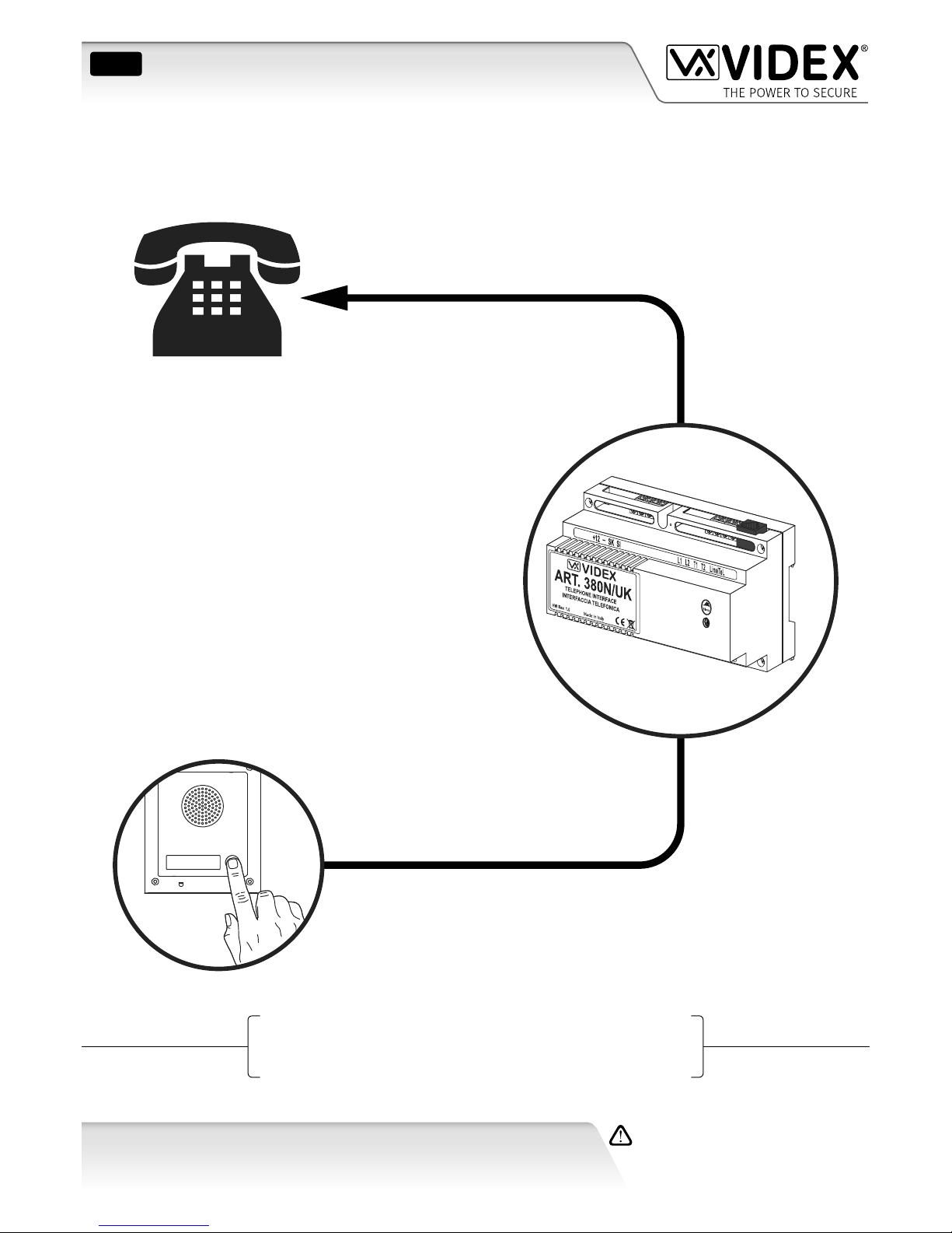
The Art.380N/UK would connect to the existing master socket
in the property. The primary telephone would be connected to
a new master socket from the Art.380N/UK, while the additional
telephone would be connected to a secondary socket, see Fig.6.
Art.380N/UK
MASTER
SOCKET
SECONDARY
SOCKET
EXISTING MASTER SOCKET TELEPHONE 1
(REN 1)
TELEPHONE 2
(REN 1)
Fig. 6
CONNECTING A REN BOOSTER
If more than 2 telephones are required they can be connected to
the Art.380N/UK via a REN booster (the REN booster, sometimes
referred to as a telephone extension booster, is a third party
product not supplied by Videx).
When using a REN booster it is important to note that the REN
booster itself will have a REN value (usually a REN value of 1) and
also requires it’s own power (typically 230Vac mains input).
IMPORTANT NOTE: When using a REN booster the Art.380N/UK
must be in PABX mode (refer to PABX setup and programming
on page 16). It will then be necessary to press ‘0’ on the
telephone to get an outside line.
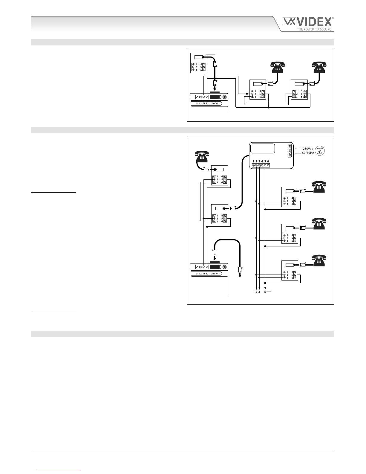
Like in the example above the Art.380N/UK would connect to the
existing master socket in the property. The REN booster would
then be connected to a new master socket from the Art.380N/
UK, while additional telephones would be connected to the
secondary sockets connected from the REN booster, see Fig.7.
In the example, Fig.7, a secondary socket can still be connected
from the new master socket from the Art.380N/UK as the overall
REN value of the REN booster and Telephone 1 does not exceed
a REN value of 2. Additional secondary sockets can be connected
from the REN booster providing the overall REN value of the
telephones connected on the system (i.e. into the secondary
sockets) does not exceed a total REN value of 8, the maximum
REN value output of the REN booster.
Art.380N/UK
(setup in PABX mode)
REN BOOSTER
(REN 1)
(max. REN
output = 8)
SECONDARY
SOCKET
TELEPHONE 4
(REN 1)
SECONDARY
SOCKET
TELEPHONE 3
(REN 1)
NEW MASTER
SOCKET
SECONDARY
SOCKET
TELEPHONE 2
(REN 1)
SECONDARY
SOCKET
TELEPHONE 1
(REN 1)
PLUG INTO
EXISTING
MASTER
SOCKET
Connections to additional Secondary
Sockets up to a total REN value of 8
Fig. 7
IMPORTANT NOTE:The REN booster shown in Fig.7 above is to show how a REN booster can be connected from the Art.380N/UK
and it should be noted that the maximum REN value output of the REN booster may vary from manufacturer to manufacturer.
The total REN value output can usually be found in any accompanying technical documentation for the device.
CONNECTING TO A PABX TELEPHONE SYSTEM
There are two ways in which to connect the Art.380N/UK to a PABX telephone system:
• Connecting into a spare analogue trunk input (sometimes referred to as a trunk card);
• Connecting into an analogue extension.
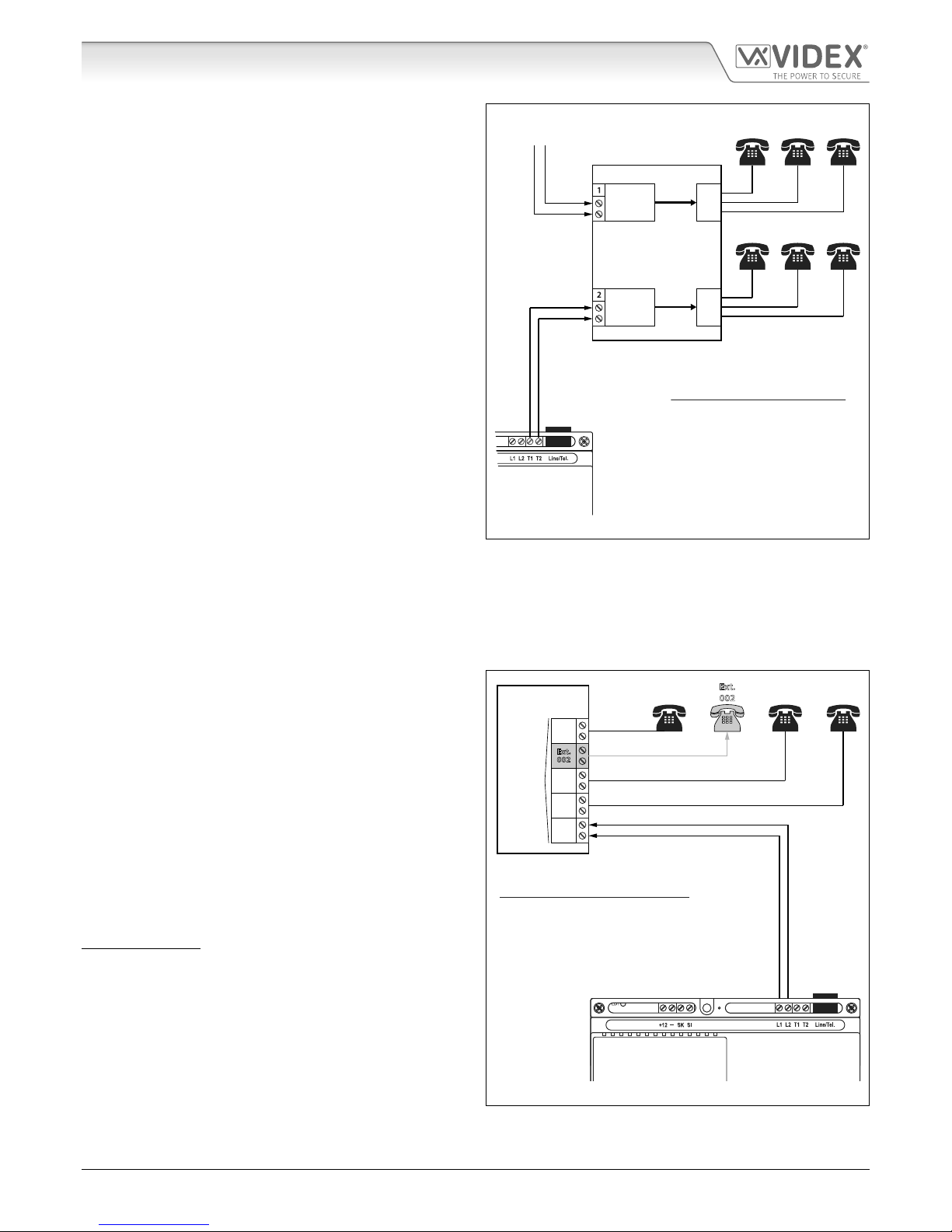
Connecting into a Spare Analogue Trunk Input
Terminals T1 andT2 from the Art.380N/UK would connect directly into a spare analogue trunk input on the PABX telephone system.
In this instance the Art.380N/UK would be setup in PABX mode (refer to PABX setup and programming on page 16) and would
provide the line voltage, approximately 57-58Vdc, that would usually be provided by an ordinary incoming telephone line, refer to
Fig.8 on page 8.
The only other connections required from the Art.380N/UK would be the connections to the intercom door station, relay connections
to a lock (or volt free if connecting to an automated gate) and possibly the auxiliary outputs A1 and A2 if other devices are being
activated. Refer to the wiring diagrams on pages 19 - 22 for further examples.
Connections to Telephones & Other Devices

66250010-EN - V2.0 - 24/09/18
- 8 -
Telephone Interface Module
Art. 380N/UK Telephone Interface Module - Installation Instructions
Connections to Telephones & Other Devices
In the example, see Fig.8, the PABX telephone system would need
to be setup and programmed by a qualied telephone engineer.
System Operation:
When an outside call on the incoming telephone line comes into
the PABX telephone system on trunk input 1 the telephone system
would dial hunt group 100 which would then call extensions 001
to 003.
When an incoming call signal from the Art.380N/UK comes into
the telephone system on trunk input 2 the telephone system
would dial the hunt group 200 which would then call extensions
004 to 006.
In this instance the Art.380N/UK would need to be setup in PABX
mode (refer to page 16 for setup of this mode) as the Art.380N/
UK would need to generate the 57-58Vdc line voltage required
for trunk input 2.
Art.380N/UK
(setup in PABX mode)
PABX TELEPHONE SYSTEM
Analogue
Trunk Input
Ext.
001
003
Spare
Analogue
Trunk Input
Ext.
004
006
DIAL 100
DIAL 200
Ext.
001
Ext.
002
Ext.
003
Ext.
004
Ext.
005
Ext.
006
Incoming
Telephone Line
PABX Telephone System Operation
A call signal on the incoming
telephone line into trunk input 1 is
programmed to dial hunt group 100.
A call signal from the Art.380N/UK
into trunk input 2 is programmed to
dial hunt group 200.
Fig. 8
Connecting into an Analogue Extension
Terminals L1 and L2 from the Art.380N/UK would connect into a spare analogue telephone extension on the PABX telephone
system. In this instance the Art.380N/UK would be setup in DIVERT mode and would require a telephone/extension or hunt group
number programmed into it (refer to divert setup and programming on page 15), see Fig.9.
As in the previous example the only other connections required from the Art.380N/UK would be the connections to the intercom
door station, relay connections etc.
In the example, see Fig.9, the Art.380N/UK is connected into
extension 005 on the telephone system.
System Operation:
In this example any extension on the telephone system (001 to
005) can call one another, i.e. for extension 001 to call extension
004 the user would pick up the handset on the telephone and
dial 004.
When a call is placed from the external intercom station and
triggers the Art.380N/UK the telephone interface will dial the
programmed divert number (extension) 002.
In this instance the Art.380N/UK would need to be setup in
DIVERT mode and programmed with an extension number to
dial, in the example it is programmed with extension 002 (refer to
page 15 to setup DIVERT mode and program a DIVERT number).
IMPORTANT NOTE: The minimum number of digits that the
Art.380N/UK can dial when in DIVERT mode is 3 digits.
Art.380N/UK
(setup in DIVERT mode)
Art.380N/UK setup and programming
The Art.380N/UK is setup in divert mode (using the
111 command) and is programmed to dial extension
Ext.002 (using the 321 002 # command).
PABX TELEPHONE
SYSTEM
Ext.
001
Ext.
002
Ext.
003
Ext.
004
Analogue
Extensions
Ext.
005
Ext.
001
Ext.
002
Ext.
003
Ext.
004
Fig. 9

66250010-EN - V2.0 - 24/09/18
9
Telephone Interface Module
Art. 380N/UK Telephone Interface Module - Installation Instructions
CABLE SIZE GUIDE
Refer to the tables below for the connections for the mains power supply input to the Art.380N/UK and the lock release connections
from the Art.380N/UK relay output.
230240VAC MAINS INPUT
Distance / Cable no more than 20m from switched fuse spur Cable Type
Cross Sectional Area (CSA) 1.0mm22 core, 1.0mm2mains ex
LOCK RELEASE CONNECTIONS C/NO TERMINALS
Distance 20m 50m 100m
Cross Sectional Area (CSA) 0.5mm21.0mm21.5mm2
The maximum acceptable resistance for the above cables = 3 Ohms or less for best possible performance.
For all other connections refer to the table below.
Minimum Cable Requirements Cable Type
Connections 50m 100m 200m For the connections
shown in the table
it is recommended
that a multipair cable
compliant to CW1308
spec is used for internal
wiring. For all external
wiring an external grade
equivalent multipair
cable that is compliant
to CW1128 spec should
be used.
20.25mm20.35mm20.5mm2
10.25mm20.35mm20.5mm2
30.5mm20.75mm21.0mm2
60.25mm20.35mm20.5mm2
NO Refer to lock release connections table above
C
A2 0.25mm20.35mm20.5mm2
A1 0.25mm20.35mm20.5mm2
+12 0.5mm20.75mm21.0mm2
The maximum acceptable resistance for the connections: 2, 1, 6, A2 and A1 = 7.5 Ohms or less for best possible performance.
The maximum acceptable resistance for the connections: 3, NO, Cand +12 = 3 Ohms or less for best possible performance. Please
note that all cable sizes shown in the tables above are the minimum cable requirements.
For the connections L1, L2, T1 and T2 it is recommended that a multipair BT spec cable, CW1308 or equivalent should be used.
IMPORTANT NOTE: Only bare copper (BC) cable should be used (solid or stranded is acceptable).Please be aware that when
selecting a cable the following should NOT be used: Copper Coated Steel (CCS) and Copper Clad Aluminium (CCA). While these
types of cable may oer a low cost solution they will have a higher resistance than pure copper cable and can aect the overall
performance of the system therefore Videx DO NOT recommend these types of cable.
GENERAL INSTALLATION NOTES
• Check that all components are free from damage before installing (do not proceed with installation in the event of damage).
• Keep all packaging away from children.
• Do not obstruct the ventilation openings or slots on any of the devices.
• All connections to mains voltages must be made to the current national standards (I.E.E. wiring regulations for the UK or
the appropriate standards of your country).
• Install an appropriate fused spur or isolation switch to isolate the mains.
• Isolate the mains before carrying out any maintenance work on the system.
• Avoid water ingress into the rear of the module, always seal the module frame after installation using a suitable silicon
based sealant.
• All intercom and access control cables must be routed separately from the mains.
General Directions for Installation

66250010-EN - V2.0 - 24/09/18
10
Telephone Interface Module
Art. 380N/UK Telephone Interface Module - Installation Instructions
General Directions for Installation
LOCK RELEASE WIRING AND BACK EMF PROTECTION
In most cases when connecting an Art.380N/UK to a Videx intercom system the electric lock release would be connected directly
from the intercom door station (refer to the wiring diagrams on pages 19 - 22 for examples). It is however possible to connect the
lock release directly through the relay contacts C/NO on the Art.380N/UK if the need arises.
When tting the lock release through the relay contacts C/NO back EMF protection will be required. If tting an AC lock release then
a 100nF ceramic disc capacitor must be tted across the terminals of the lock, shown in Fig.10. If tting a DC lock release (fail secure
or fail safe) then a 1N4002 diode must be tted across the terminals on the lock, shown in Fig.11.
IMPORTANT NOTE: A separate power supply capable of powering the lock will be required whether tting an AC lock (fail
secure) or when tting a DC lock (fail secure or fail safe).
It should also be noted that if a fail safe lock is being connected the Art.380N/UK relay will need to be programmed for C/NC
(common normally closed) operation using the programming code 101, refer to onboard relay reversal (C/NO or C/NC) notes
on page 14.
12V AC
FAIL SECURE
LOCK RELEASE
12Vac
input
100nF CAP
(or 14-20V MOV) 12V DC
FAIL SECURE
OR FAIL SAFE
LOCK RELEASE
12Vdc
input
1N4002
DIODE
Fig. 10 Fig. 11
If a 100nF ceramic disc capacitor or a 1N4002 diode are not available then a 14 - 20V MOV (metal oxide varistor) can be tted across
the lock terminals instead. The MOV can be tted on both an AC and DC lock and is not polarity conscious, follow Fig.10 for wiring.
CONNECTION TO MAINS, SAFETY AND GUIDANCE NOTES
IMPORTANT: PLEASE READ THESE INSTRUCTIONS CAREFULLY BEFORE COMMENCING WITH THE INSTALLATION.
Videx recommends that any cabling and Videx product be installed by a competent and qualied electrician, security installation
speclialist or communications engineer.
• DO NOT install any Videx product in areas where the following may be present or occur:
• Excessive oil or a grease laden atmosphere.
• Corrosive or ammable gases, liquids or vapours.
• Possible obstructions which would prevent or hinder the access and/or removal of the Videx product.
MAINS CONNECTION
The system MUST be installed in accordance with the current I.E.E regulations (in particular I.E.E. Wiring regulations BS7671 for the
UK), or the appropriate standards of your country, in particular Videx recommends:
• Connecting the system to the mains through an all-pole circuit breaker (refer to Fig.12) which shall have contact separation
of at least 3mm in each pole and shall disconnect all poles simultaneously.

66250010-EN - V2.0 - 24/09/18
11
Telephone Interface Module
Art. 380N/UK Telephone Interface Module - Installation Instructions
• That the all-pole circuit breaker shall be placed in such a way to allow for easy access and the switch shall remain readily
operable.
• Ensuring that the mains supply (Voltage, Frequency and Phase) complies with the product rating label.
• Isolating the mains before carrying out any maintenance work on the system.
FUSE
N
L
Mains
1 PHASE SUPPLY
(220 - 240Vac, 50/60Hz)
SWITCHED FUSE SPUR
Fig. 12
POWER SUPPLY INSTALLATION AND MOUNTING
Follow the steps below when tting the Art.380N/UK:
• First remove the terminal side covers by unscrewing the retaining screws.
• Fix the Art.380N/UK to a DIN rail, following Fig.13, Fig.14 and Fig.15, or directly to the wall using 2x rawl plugs and 2x
expansion type screws, see Fig.16 (2x40mm, Ø3.5mm self-tapping masonry screws and 2x40mm, Ø4mm nylon rawl plugs
will suce).
• Switch OFF the mains using the circuit breaker (mentioned previously) and then make the connections as shown on the
installation wiring diagrams (refer to pages 19 - 22 for examples).
• Check the connections and secure the wires into the terminals ensuring that the low voltage (signal) cables are routed
separately from the high voltage (mains) cables.
• Replace the terminal covers and x them back into place using the relevant screws.
• When all connections are made restore the mains supply.
Fig. 13 Fig. 14
2x rawl
plugs
2x expansion
type screws
Fig. 15 Fig. 16
General Directions for Installation

66250010-EN - V2.0 - 24/09/18
- 12 -
Telephone Interface Module
Art. 380N/UK Telephone Interface Module - Installation Instructions
Programming the Art.380N/UK
PROGRAMMING OVERVIEW
Most of the features of the Art.380N/UK can be adjusted using the telephone keypad connected to the master socket that is wired from
the output terminals T1 and T2 of the Art.380N/UK. The telephone used will need to be a ‘tone dial’ telephone capable of producing
DTMF tones. Conrmation tones can be heard at the end of each segment of programming to indicate if the information entered has
been accepted and understood or if the information has not been understood and therefore will require entering again. If during the
programming, a mistake is made, simply hang up the telephone and start again.
TONES OVERVIEW
• Upon lifting the handset you should hear the telephone line dial tone. If the system is in PABX mode you will still hear a
continuous line tone, however this will be at a higher frequency to the one normally heard on a telephone line.
• On entering ** to gain access to the programming functions the line tone will change to a higher frequency. When in
PABX mode the line tone stays the same.
• Upon pressing the rst digit of the programming command the line tone will stop.
• As you enter the command digits on the telephone keypad you will hear the DTMF tones.
• Upon completion of the command you will hear a double tone beep to conrm the command was accepted. If you hear
a number of fast beeps or an engaged tone, the command has not been accepted in which case replace the handset
and start again.
• The fast beeps will also indicate an incorrect access code if this facility has been setup to secure access to the programming
menu.
The following table is a quick guide to the programming. This will be followed by a more descriptive guide to the programming.
IMPORTANT NOTE: The programming menu is protected. To enter into programming mode rst pick up the telephone handset
(ensuring the telephone line dial tone is present) and enter ** 371 on the keypad and listen for the double tone conrmation
beep.
These commands can be carried out back to back without having to hang up the handset. If you do hang up it will be necessary
to unlock the programming again.
If the access code feature is enabled then this must be entered after pressing **, e.g. if the access code is '1234' then pick up the
handset and press ** 1234 371 on the keypad and listen for the double tone conrmation beep.
After accessing the programming mode the following programming commands become available:
Description Code Variant ‘X’ Default ‘X’ Page
Relay reversal (NO or NC). 10 X X = 1 or 0 (1for a normally closed circuit for use with fail safe lock
releases and 0for a normally open circuit for fail secure lock releases).
0 14
Alternate between local
call and divert mode.
11 X X = 1 or 0 (1to set for divert mode and 0for local mode). 0 15
Dial in facility (enable or
disable).
12 X X = 1 or 0 (1for enabling the dial in facility and 0for disabling the
dial in facility).
0 15
Pulse dial mode 13 X X = 1 or 0 (1to enable the pulse dial facility and 0to disable the pulse
dial facility).
0 16
PABX mode 14 X X = 1 or 0 (1for PABX mode and 0for normal mode). 0 16
Disable ** mode 17 X X = 1 or 0 (1to disable ** reading and 0to enable ** reading). 0 17
Direct DTMF reading 18 X X = 1 or 0 (1to enable direct DTMF reading and 0to disable direct
DTMF reading).
1 17
AUX 2 direct control 19 X X = 1 or 0 (1for direct control by user and 0to allow A2 to automatically
trigger upon a call).
1 14
Access code enable/
disable for local use
20 X X = 1 or 0 (0to enable the code for local use and 1to disable the code
during local use).
1 16
Number of rings 21 X X = 0 to 9 (0= 10 rings, 1- 9= number of rings). 6 14

66250010-EN - V2.0 - 24/09/18
- 13 -
Telephone Interface Module
Art. 380N/UK Telephone Interface Module - Installation Instructions
Door open time 22 X X = 0 to 9 (0= 1 second, 1- 9multiplied by 2, i.e. if X= 3 then time =
6 seconds; if X= 4 then time = 8 seconds).
3 14
Door open key 23 X X = 0, 8 or 9. 0 14
Divert call/ dial in time 24 X X = 0 to 9 (Xmultiplied by 30 seconds = time, i.e. if X= 2 then time =
60 seconds; if X= 4 then time = 120 seconds).
2 15
Dial in answer after a
number of rings
25 X X = 0 to 9 (0= 10 rings, 1- 9= number of rings before automatically
answering).
5 15
Tone detection 26 X X = 1 or 0 (1to enable tone detection and 0to disable tone detection). 1 17
Speech volume towards
the entrance panel
27 X X = 1 to 9 (1= lowest volume and 9= maximum volume). 5 17
A1 auxiliary output
control
28 X X = 1 or 0 (1for momentary trigger and 0for latching trigger). 1 14
A2 auxiliary output
control
29 X X = 1 or 0 (1for momentary trigger and 0for latching trigger). 1 14
At home control 30 X X = 1 or 0 (1to disable home control and 0to activate home control). 1 17
Access code 31 XXXX X = 4 digit access code (note that this code must begin with either
1, 2, 3 or 4).
no code 16
Divert phone number 321 n # n = telephone number (e.g. to program the number 0123 456789
would be 321 0123456789#, always conrm the number with the #
key at the end. A minimum of 3 digits can be used for the number).
N/A 15
Revert to default settings
(reset)
33 1111 Resets all settings back to factory default. N/A 13
Reassurance tone at the
door panel
34 X X = 1 or 0 (1to activate the reassurance tone and 0to deactivate the
reassurance tone).
0 17
Divert to number after n
seconds
35 X X = 0 to 9 (0to disable the divert and 1 - 9 multiplied by 4 = time, i.e.
if X= 3 then time = 12 seconds before automatic divert).
0 15
Divert mode audio
automatically ON/OFF
36 X X = 1 or 0 (1to manually open the speech by pressing 2after
answering the call and 0to enable the speech automatically).
0 16
PROGRAMMING AND USER FUNCTIONS EXPLAINED
INITIAL SETUP AND RESET
Begin by resetting the Art.380N/UK to the factory defaults using the programming command: ** 371 33 1111.
IMPORTANT NOTE: If you are unable to reset using this process because an access code has been enabled but you are not sure
what it is then follow the manual reset procedure:
1. Switch OFF the mains power to the Art.380N/UK;
2. Short out the terminals -and SK, see Fig.17;
3. Switch ON the mains power to the Art.380N/UK;
4. Remove the short between terminals -and SK, see
Fig.18;
5. The Art.380N/UK has now been reset to the factory
default settings.
This method will also switch the Art.380N/UK into PABX mode
so unless this mode is required in order to revert the unit back
to normal mode, pickup the handset and type ** 371 14 0 and
listen for the line tone to change to the normal dial tone.
Fig. 17
Fig. 18
Programming the Art.380N/UK

66250010-EN - V2.0 - 24/09/18
- 14 -
Telephone Interface Module
Art. 380N/UK Telephone Interface Module - Installation Instructions
Programming the Art.380N/UK
PROGRAMMING COMMANDS AND ADJUSTMENTS
The following adjustments can be used to program the system to the user's requirements. Remember after picking up the telephone
handset to press ** 371 on the handset keypad to unlock the programming commands and listen for the double tone conrmation
beep.
ADJUST THE NUMBER OF RINGS
The Art.380N/UK can be programmed to ring the telephone(s)
for as little as 1 ring or for a maximum of 10 rings, using one of
the following codes shown in the table.
By default this is set to 6 rings.
Code Rings Code Rings
21 1 1 21 6 6 (default)
21 2 2 21 7 7
21 3 3 21 8 8
21 4 4 21 9 9
21 5 5 21 0 10
ADJUST THE DOOR OPEN TIME
The Art.380N/UK can be programmed to release the door for as
little as 1 second or for a maximum of 18 seconds, using one of
the following codes shown in the table.
By default this is set to 6 seconds.
Code Time (secs) Code Time (secs)
22 0 1 22 5 10
22 1 2 22 6 12
22 2 4 22 7 14
22 3 6 (default) 22 8 16
22 4 8 22 9 18
ONBOARD RELAY REVERSAL C/NO OR C/NC
The relay contacts of the Art.380N/UK can be programmed to
either be normally open going closed (C/NO, default position)
or programmed to be normally closed going open (C/NC), using
one of the following codes shown in the table.
Code Status Code Status
10 1 NC 10 0 NO (default)
CHANGING THE DOOR OPEN BUTTON 0, 8 OR 9
The door open button on the telephone handset is button 0
(default) however this can be changed to either button 8or
button 9, using one of the following codes shown in the table.
Code Button Code Button
23 0 0 (default) 23 5 8
23 1 9
SETTING UP THE AUXILIARY OUTPUTS A1 AND A2
There are two auxiliary outputs available on the Art/380N/UK, A1 and A2. These outputs are a switch 0V (open collector, 200mA
max.) signal which can be used for a number of facilities including activating additional dry contact relays. The outputs can be set
to latch on activation or switch momentarily (default).
To setup the auxiliary outputs A1 and A2 use one of the following
codes shown in the table. By default both outputs are set to 1,
momentary trigger.
Code Output Code Output
28 0 A1 latching 28 1 A1 momentary
29 0 A2 latching 29 1 A2 momentary
USING THE AUXILIARY OUTPUTS
• To activate auxiliary output A1 during a call simply press button 5on the telephone. If the auxiliary output is set to latch then
it will be necessary to press button 5again to unlatch the output.
• To activate auxiliary output A1 without a call being in progress simply pick up the telephone handset and press the buttons
** 5 on the telephone. If the output is set to latch, follow the same procedure to unlatch.
• To activate auxiliary output A2 during a call simply press button 6on the telephone. If the auxiliary output is set to latch then
it will be necessary to press button 6again to unlatch the output.
• To activate auxiliary output A2 without a call being in progress simply pick up the telephone handset and press the buttons
** 6 on the telephone. If the output is set to latch, follow the same procedure to unlatch.
Additionally, auxiliary output A2 can be programmed to
automatically activate when a call is placed.
IMPORTANT NOTE: If A2 is set to activate automatically it cannot
also be set to latch as indicated above.
Code Output Code Output
19 0 Automatic 19 1 Manual

66250010-EN - V2.0 - 24/09/18
- 15 -
Telephone Interface Module
Art. 380N/UK Telephone Interface Module - Installation Instructions
Programming the Art.380N/UK
DIAL IN FACILITY SETUP
The dial in facility can be used to allow a caller from an outside telephone line to dial into the Art.380N/UK and access the functions
available. For example this could be to open the door or activate an auxiliary output.
ENABLING / DISABLING THE DIAL IN FACILITY
To setup the dial in facility use one of the following codes shown
in the table. By default his facility is disabled. Code Dial In Facility Status
12 0 Disabled (default)
12 1 Enabled
DIAL IN ANSWER AFTER A NUMBER OF RINGS
The Art.380N/UK can count the number of rings before it
activates and takes hold of the call. This can be set from as little
as 1 ring up to a maximum of 10 rings. To setup the number of
rings use one of the following codes shown in the table.
IMPORTANT NOTE: A standard BT line telephone ring is a
double ring and therefore counts as two rings.
Code Rings Code Rings
25 1 1 25 6 6
25 2 2 25 7 7
25 3 3 25 8 8
25 4 4 25 9 9
25 5 5 25 0 10
DIAL IN TIME / DIVERT TIME
The dial in time / divert time is the maximum time that a call
will last before clearing down (hanging up) and releasing the
telephone line. The dial in time / divert time can be set from 30
seconds up to a maximum of 300 seconds (5 minutes).
To setup the dial in time / divert time use one of the following
codes shown in the table.
Code Time (secs) Code Time (secs)
24 1 30 24 6 180
24 2 60 24 7 210
24 3 90 24 8 240
24 4 120 24 9 270
24 5 150 24 0 300
DIVERT CALL SETUP
The divert facility allows a call to be diverted to another telephone number. When in divert mode it is recommended that you use
a 4 digit access code to restrict the functions of the Art.380N/UK to authorised callers (also refer to access code setup on page 16).
PROGRAMMING A DIVERT TELEPHONE NUMBER
To program a divert telephone number use the programming
command shown in the table. The telephone number stored can
be a minimum of 3 digits and a maximum of 40 digits in length.
Code Description
321 n# where n = the telephone number to divert to
IMPORTANT NOTE: When programming the divert telephone number remember to include the # after the telephone number
otherwise the Art.380N/UK will not accept the programming command.
ALTERNATE BETWEEN LOCAL CALL MODE AND DIVERT MODE
When in local call mode and a call is placed, the Art.380N/UK
will only ring the telephone connected into the master socket
wired from T1 and T2. When in divert mode and a call is placed,
the Art.380N/UK will only ring the divert telephone number that
is stored without calling the local telephone connected into the
master socket.
Code Mode
11 1 Divert mode
11 0 Local call mode (default)
To switch between the 2 modes use one of the codes shown in
the table above.
DIVERTING THE CALL AUTOMATICALLY AFTER A PRESET NUMBER OF SECONDS
When this mode is enabled, the telephone in the property
(connected into the master socket) will ring for the number of
seconds programmed and if after this period the call is still not
answered, it will divert to the pre-programmed divert telephone
number.
To set the time before diverting use one of the following codes
shown in the table. By default this feature is disabled.
Code Time (secs) Code Time (secs)
35 1 4 35 6 24
35 2 8 35 7 28
35 3 12 35 8 32
35 4 16 35 9 36
35 5 20 35 0 Disabled

66250010-EN - V2.0 - 24/09/18
- 16 -
Telephone Interface Module
Art. 380N/UK Telephone Interface Module - Installation Instructions
Programming the Art.380N/UK
AUTOMATICALLY OPEN SPEECH WHEN ANSWERING A DIVERT CALL
When this mode is set to 1 it will be necessary for the user to press
2 on the telephone after answering a call that has been diverted
to it. This feature disables the door entry panel amplier until 2
is pressed on the telephone so that no dialling tones are heard
and the caller is not aware that the initial call is being diverted.
Code Mode
36 1 Must press 2 to open speech
36 0 Speech opens automatically (default)
Example 1: A call diverted to a mobile phone when **36 1 is set (enabled) -
1. The mobile phone will ring (no sound will be heard from the door panel speaker) and the caller display will show
that it is from the telephone number attached to the Art.380N/UK (if the caller ID is enabled on the telephone);
2. The user answers the call and no sound will be heard;
3. The user then presses button 2 on the mobile phone to open speech to the door panel.
Example 2: A call diverted to a mobile phone when **36 0 is set (disabled) -
1. The mobile phone will ring (this will also be heard through the speaker at the door panel as well);
2. The user answers the call and speech will be open automatically.
To set this mode use one of the following codes shown in the table above. By default this feature is disabled (set to 0).
ACCESS CODE SETUP
The 4 digit access code is used to restrict access to the programming menu and commands. It can be disabled, setup for both local
calls and diverted calls or setup for just diverted calls.
EDIT OR DELETE THE ACCESS CODE
This programming command allows the user to edit an existing
4 digit access code (if known) or delete the access code.
Use one of the following codes shown in the table to setup or
delete the access code (where XXXX = the 4 digit code required).
Code Mode
31 XXXX Change the code to XXXX
31 1111 Delete the code
ENABLE / DISABLE THE 4 DIGIT ACCESS CODE FOR LOCAL CALLS
This programming command allows the user to enable or disable
the 4 digit access code for local calls. By default this feature is
disabled. Use one of the following codes shown in the table to
enable or disable the access code.
Code Access Code Status
20 0 4 digit code enabled
20 1 4 digit code disabled (default)
SPECIALISED SETUP
The following options can be adjusted for specialised situations. For standard installations these settings will not normally need to
be adjusted.
PULSE MODE
The pulse mode facility can be used with older pulse style
telephones that cannot generate DTMF dial tones.
Use one of the following codes shown in the table to enable or
disable pulse mode.
Code Pulse Mode
13 0 Disabled (default)
13 1 Enabled
PABX MODE
PABX mode can be used on systems which do not have a
telephone line or have a telephone line but needs to be isolated
from it. When this is enabled it will be necessary to press 0on the
telephone. to select the telephone line before dialing a number.
Code PABX Mode
14 0 Disabled (default)
14 1 Enabled
Use one of the following codes shown in the table above to enable or disable PABX mode.
IMPORTANT NOTE: The Art.380N/UK can also be put into PABX mode following the 'hard-wired' reset procedure described on
page 13. Remember that this method will also reset the Art.380N/UK back to factory defaults so any programming made prior to
the reset will need to be re-programmed again.

66250010-EN - V2.0 - 24/09/18
- 17 -
Telephone Interface Module
Art. 380N/UK Telephone Interface Module - Installation Instructions
Programming the Art.380N/UK
DISABLE ** MODE
An alternative to using ** to enter programming is to use the
RECALL button on the telephone (pressed twice i.e. RECALL,
RECALL) or pressing the hook switch on the telephone twice in
succession.
Code ** Status
17 0 Enabled (default)
17 1 Disabled
This method of accessing the programming menu really only applies if an older style telephone is used with the Art.380N/UK. In
most cases it is recommended that the ** command is left in default mode (remains enabled) as most modern telephones either use
the RECALL button to recall the last number that was called or they no longer have a RECALL button at all.
IMPORTANT NOTE: In the event that the ** command is inadvertently disabled it is recommended that the 'hard-wired' reset
procedure is followed, as described on page 13, in order to reset the Art.380N/UK back to factory defaults so the ** command
is reinstated.
DIRECT DTMF READING
This feature allows the DTMF tones from the telephone to be
read by the Art.380N/UK during a call without rst pressing **.
Use the following codes in the table to enable or disable the
DTMF tone reading. By default this mode is enabled.
Code DTMF Reading
18 0 Disabled
18 1 Enabled (default)
REASSURANCE TONE SETUP
This feature allows the Art.380N/UK to generate a reassurance
tone through the speaker at the door station to indicate to the
caller that a call has been placed.
Use the following codes in the table to enable or disable the
reassurance tone. By default this mode is disabled.
Code Reassurance Tone Status
34 0 Disabled
34 1 Enabled (default)
TONE DETECTION
This feature allows the Art.380N/UK to detect normal telephone
line tones such as busy,no answer,call end etc. Sometimes,
however, it may be necessary to disable this feature to avoid
false detection. Use the following codes in the table to enable or
disable the tone detection. By default this mode is enabled.
Code Tone Detection Status
26 0 Disabled
26 1 Enabled (default)
AT HOME CONTROL
This feature allows the 'divert call' to be automatically switched
OFF when active simply by picking up one of the handsets on
the output of the Art.380N/UK and then replacing it. Use the
following codes in the table to enable or disable this feature. By
default this mode is disabled.
Code At Home Control Status
30 0 Enabled
30 1 Disabled (default)
SPEECH ADJUSTMENTS
The speech volume control of the system that the Art.380N/UK is connected to can be adjusted in both directions using the control
POTs on the entrance panel speaker unit: mic , speaker and depending on the panel an additional balance POT .
Additionally the speech volume towards the entrance panel can be adjusted electronically via the telephone connected to the
Art.380N/UK using the following procedure:
1. Lift the telephone handset and press **371 to enter programming (remember to listen for the double conrmation
beep);
2. Press 27 X, where X= a volume level between 1to 9, 1being the lowest volume and 9being the maximum volume, by
default the volume level is set to 5(again listen for the double conrmation beep);
3. Replace the telephone handset and make a test call to check the speech volume.
Alternatively the speech volume towards the panel can also be adjusted when the speech is open between the panel and the
telephone during a live call following step 2 described above.
Speech volume adjustments can also be made using the balance POT located on the top side of the Art.380N/UK. This balance POT
is a particularly useful adjustment control when the Art.380N/UK is in divert call mode and the level of speech from the entrance
panel to the telephone called is low (also refer to Art.380N/UK balance POT adjustment on page 5).

66250010-EN - V2.0 - 24/09/18
- 18 -
Telephone Interface Module
Art. 380N/UK Telephone Interface Module - Installation Instructions
User Commands
USER COMMAND TABLE
The following user command table shows the user commands that can be used to activate the functions of the Art.380N/UK. If the 4
digit access code facility is active, this will be required before the command will work e.g. if the 4 digit access code is ‘4321’ the user
would press the following to open the speech to the door panel without rst being called ** 4321 7.
KEY BUTTON TO PRESS (COMMAND) FUNCTION
Either 0, 8 or 9
(depending on programming)
Open the door during the call.
1During dial in mode, pressing button 1will enable the divert facility.
2Press button 2during dial in mode to open the speech to the door panel. Also press
button 2after answering a call in divert mode to open the speech to the door panel
(when this mode is active i.e. **361).
5Activate auxiliary output A1.
6Activate auxiliary output A2 (only when auxiliary A2 has been set to direct control).
0Connect to telephone line (PABX mode only).
**7 Open speech to door without rst being called and switch between calls.
7During divert mode it will end the call and switch OFF the door panel (recommended
way to end a diverted call).
#Clear to start again if a mistake is made when typing code in divert mode.
USER COMMAND EXAMPLES
The following examples show what key buttons to press on the telephone (examples based on default settings):
• To open the speech to the door panel without rst being called: **7
• To divert to a door call while talking with someone on the telephone: **7
(NOTE: to go back to the telephone call simply hang up the handset and pick up again)
• To divert to a telephone call while talking with someone at the door panel: **7
(NOTE: to go back to the door call simply hang up the handset and pick up again)
• To open the door without rst being called: **0
• To open the door during a call: 0
• To put the system in divert mode: **111
• To take the system back out of divert mode: **110
• To activate auxiliary A1 without rst being called: **5
• To activate auxiliary A2 without rst being called: **6
• To activate auxiliary A1 during a call: 5
• To activate auxiliary A2 during a call: 6
• To activate the speech when dialling into the system: 2
• To activate the speech in divert mode (when setting **361 is set): 2

66250010-EN - V2.0 - 24/09/18
- 19 -
Telephone Interface Module
Art. 380N/UK Telephone Interface Module - Installation Instructions
Wiring Diagrams
4000 SERIES AUDIOKIT
Refer to Fig.19 for the minimum cable requirements and wiring connections between the Art.380N/UK and a 4000 series audiokit.
New Master Socket
From Existing
Master Socket
Telephone
Default Setting
Fail Secure
Lock Release
14V MOV
Fig. 19
Minimum Cable Requirement
For cable type required refer to
cable size guide notes on page 9
Art.380N/UK
Art.321
Art.4836-1
Lock Release
2 2
4
2
New Master
Socket
Existing
Master
Socket
Mains
Input

66250010-EN - V2.0 - 24/09/18
- 20 -
Telephone Interface Module
Art. 380N/UK Telephone Interface Module - Installation Instructions
8000 SERIES AUDIOKIT WITH CODELOCK
Refer to Fig.20 for the minimum cable requirements and wiring connections between the Art.380N/UK and a 8000 series audiokit.
New Master Socket
From Existing
Master Socket
Telephone
Fail Secure
Lock Release
14V MOV
Default Setting
Fig. 20
Minimum Cable Requirement
For cable type required refer to
cable size guide notes on page 9
Art.380N/UK
Art.321
Lock Release
2 2
4
2
New Master
Socket
Existing
Master
Socket
Art.8836-1
Art.VX8800
Mains
Input
Wiring Diagrams
Table of contents
Other Videx Recording Equipment manuals
Popular Recording Equipment manuals by other brands

Ricatech
Ricatech PR85 user manual

Belden
Belden Grass valley T2 4K Series installation manual

Aphex
Aphex 5200 manual

Yamaha
Yamaha Steinberg MR816SCX Service manual

Texas Instruments
Texas Instruments TIDM-1011 Design guide

Daktronics
Daktronics SPORTS WIRE 4000 INTERFACE Installation & operation manual