1 of 12
User Guide
Viega Non-Programmable
Heat/Cool Thermostat
UG-HC 566439 1219 Nonprogrammable Thermostat
MERCURY NOTICE
All of our products are mercury
free. However, if the product you
are replacing contains mercury, dispose of
it properly. Your local waste management
authority can give you instructions on
recycling and proper disposal.
Part Number 15116
Viega products are designed to be
installed by licensed and trained
plumbing, mechanical, and electrical
professionals who are familiar with Viega
products and their installation.
Installation by non-professionals may
void Viega LLC’s warranty.
This document is subject to updates.
For the most current Viega technical
literature please visit www.viega.us.
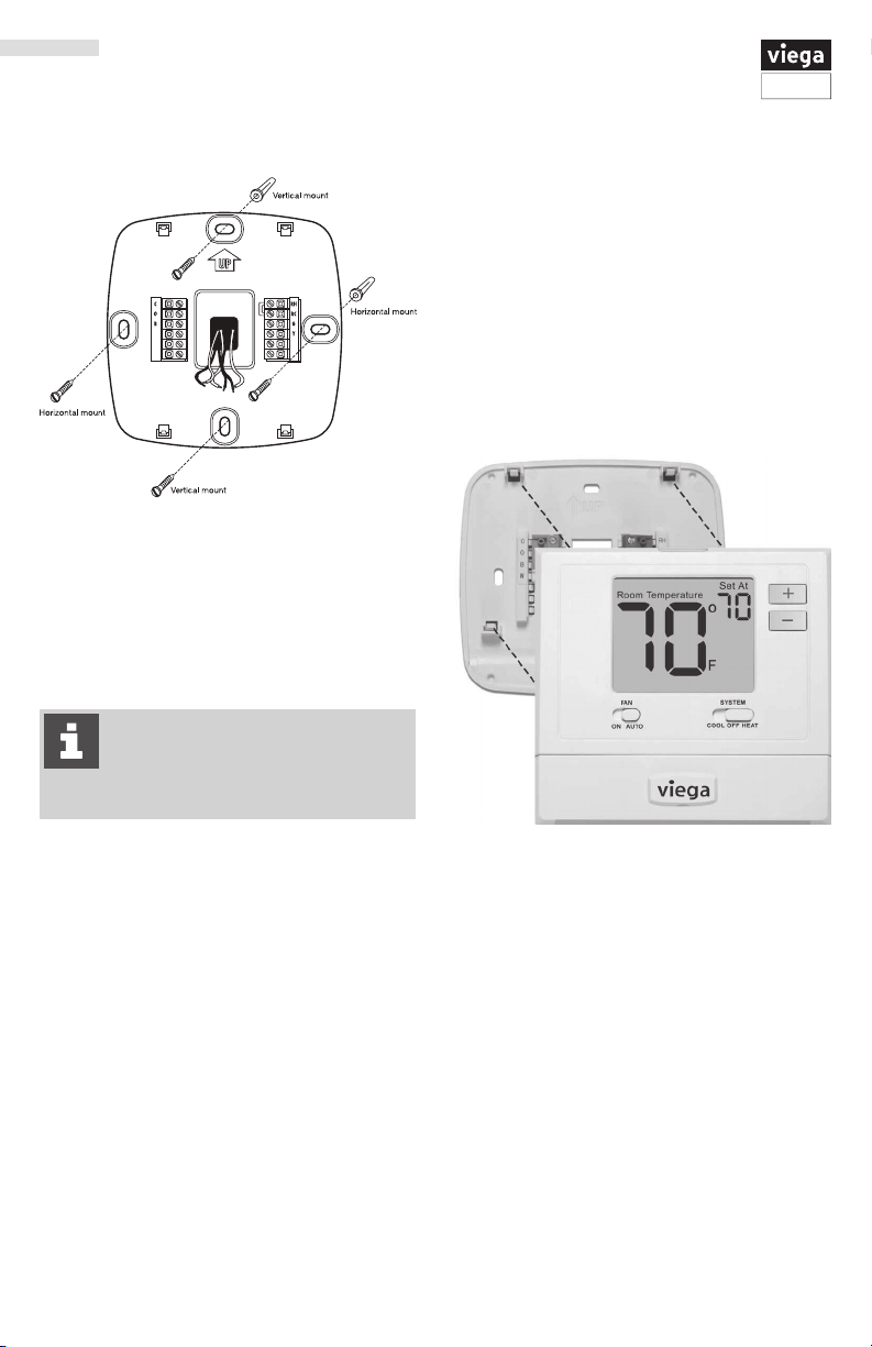
Pick an installation location that is
easy for the user to access. The
temperature of the location should be
representative of the building
Installation Tips
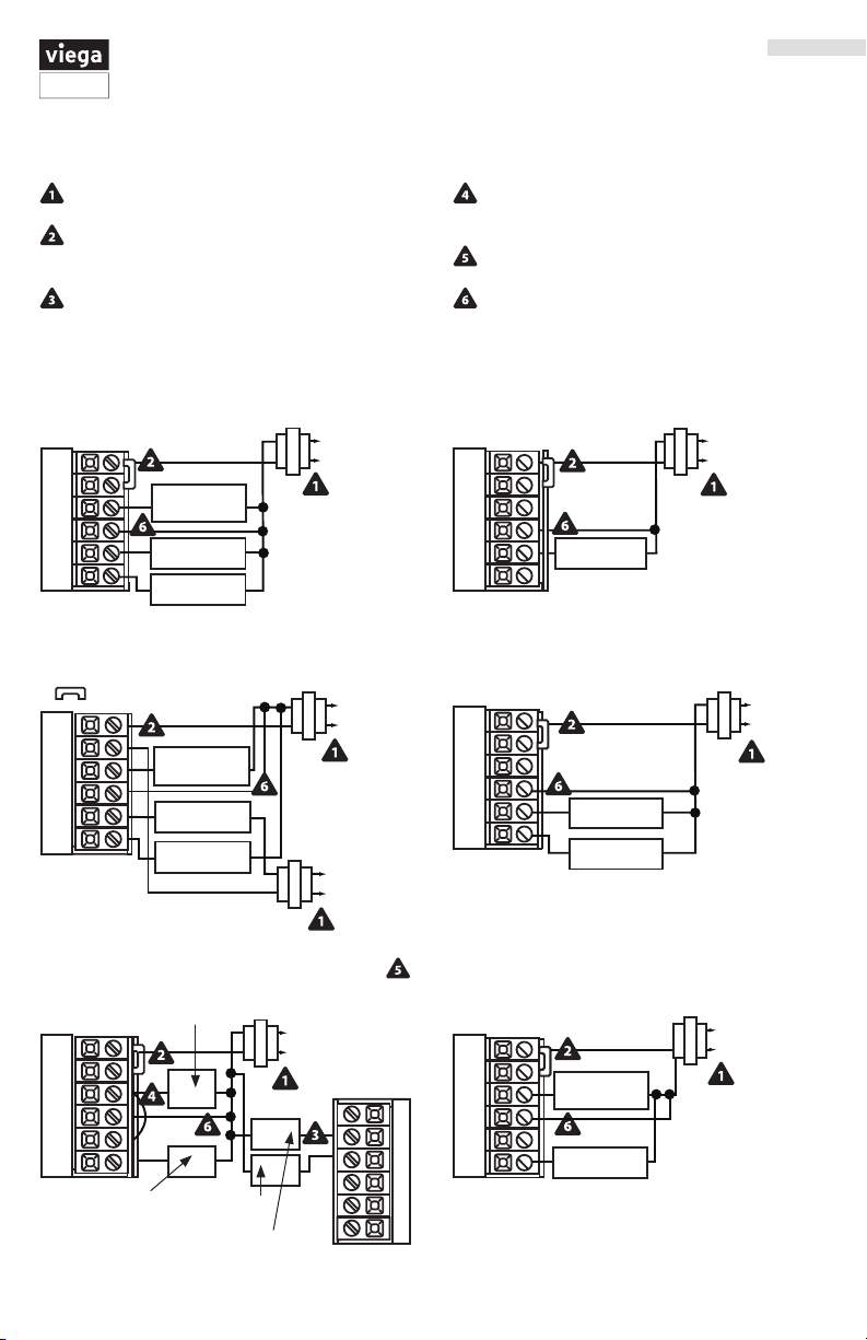
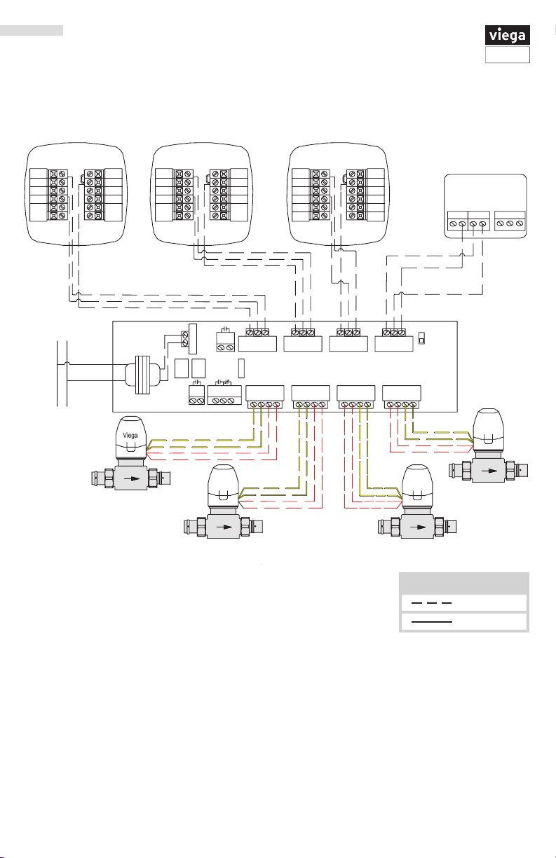
Applications Guide
The Programmable Heat/Cool Thermostat can
be use for the following applications:
■ Gas or Oil Heat
■ Electric Furnace
■ Heat Pump (No Aux. or Emergency Heat)
■ Heat Only Systems
■ Cool Only Systems
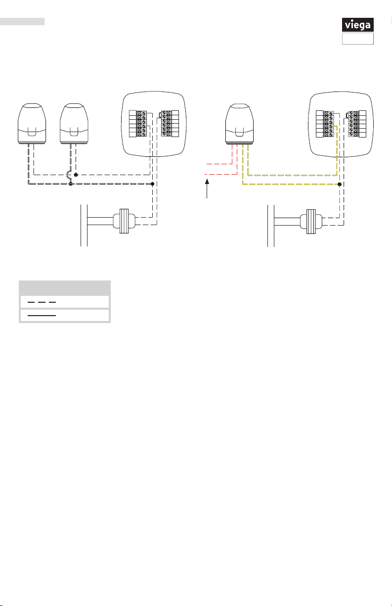
The following applications are not recommended:
■ Heat Pump (with Aux. or Emergency Heat)
■ Multi-stage Systems
Wall Locations
The thermostat should be installed approximately
4 to 5 feet above the oor. Select an area with
average temperature and good air circulation.
Do not install thermostat in locations:
■ Close to heating/cooling emitters
■ That are in direct sunlight
■ With an outside wall behind the thermostat
■ In areas that do not require conditioning
■ Where there are dead spots or drafts
(in corners or behind doors
■ Where there might be concealed chimneys or pipes
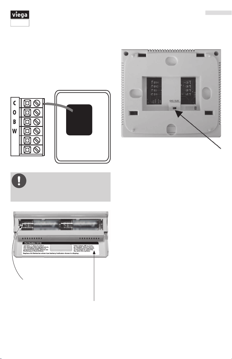
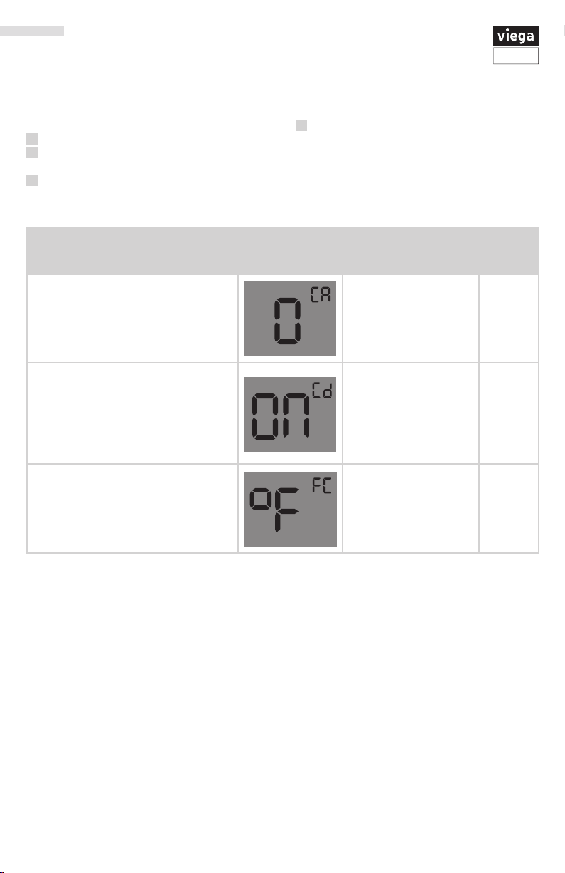
CAUTION! Electrical Hazard
Failure to disconnect the power
before beginning to install this
product can cause electrical shock or
equipment damage.
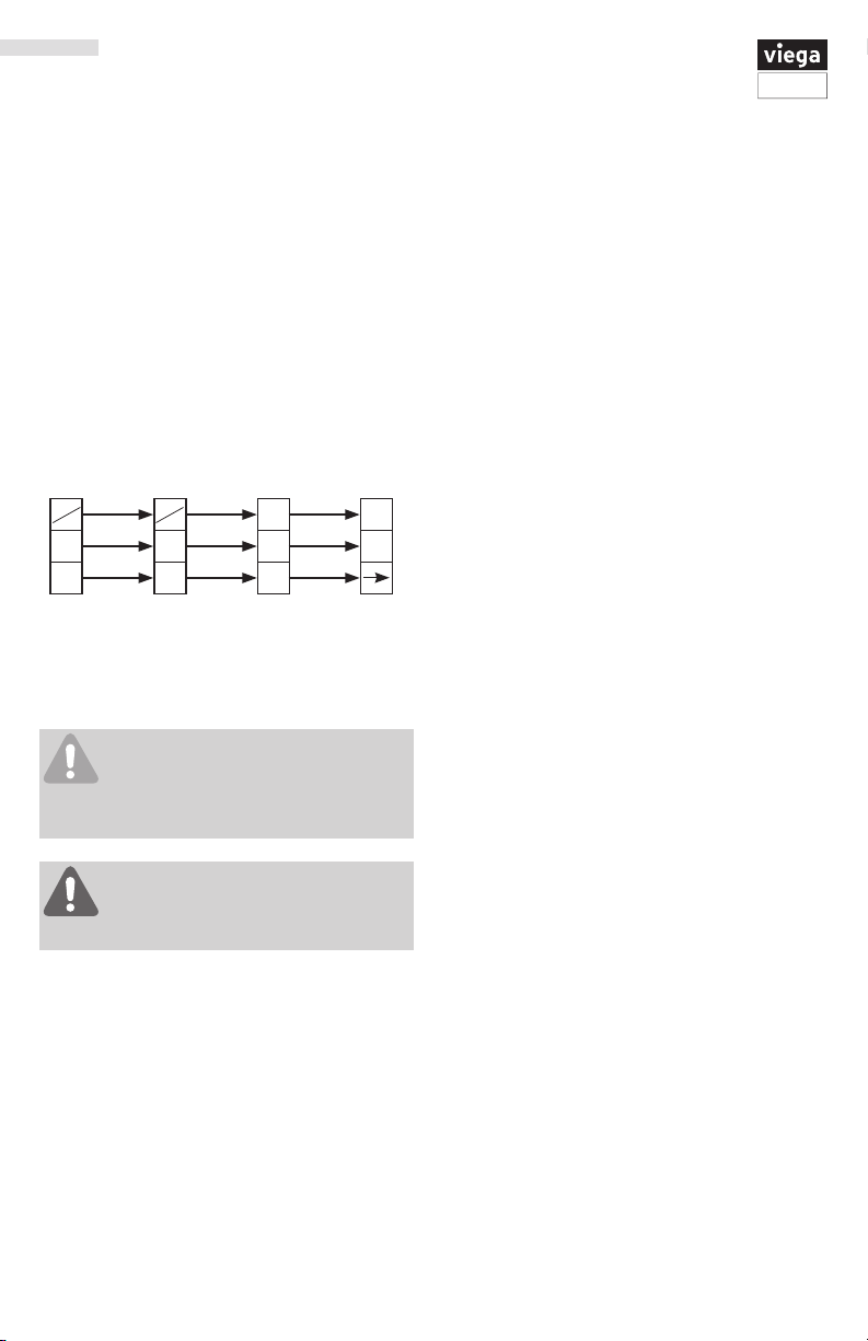
No
No
No Yes