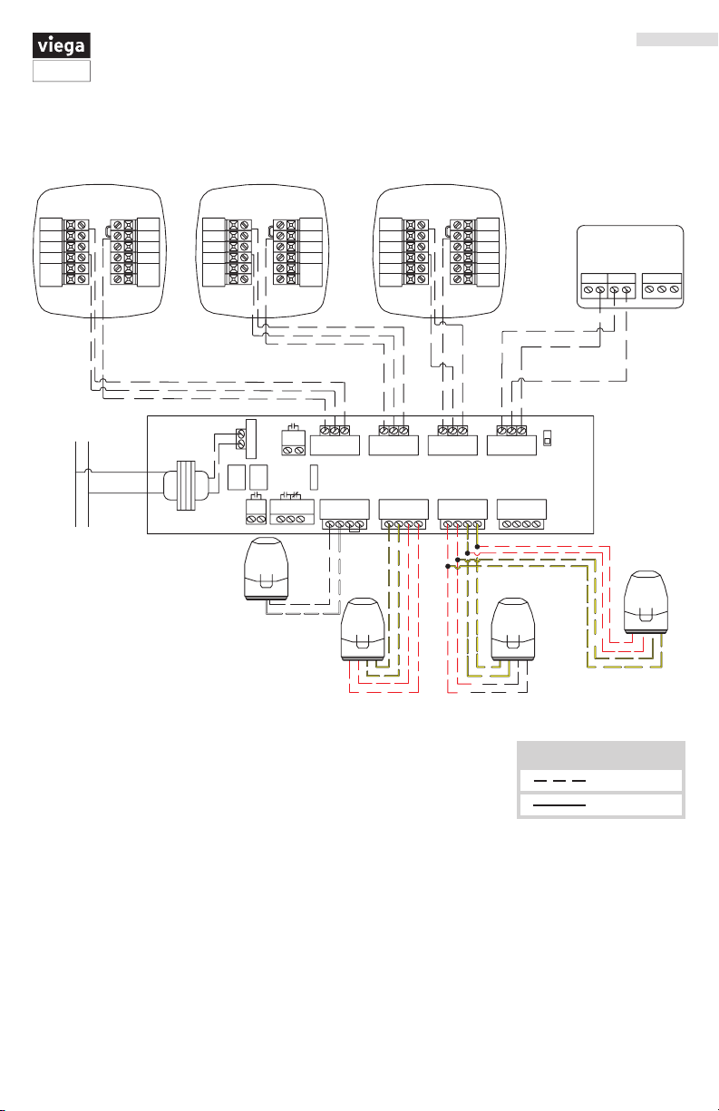
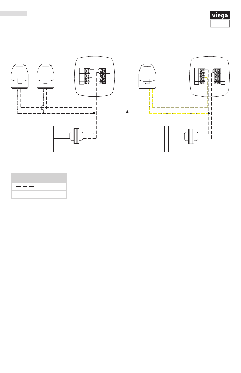
10 of 20
Viega Multifunctional Thermostat User Guide
UG-HC 566441 1219 Multifunctional Thermostat (EN)
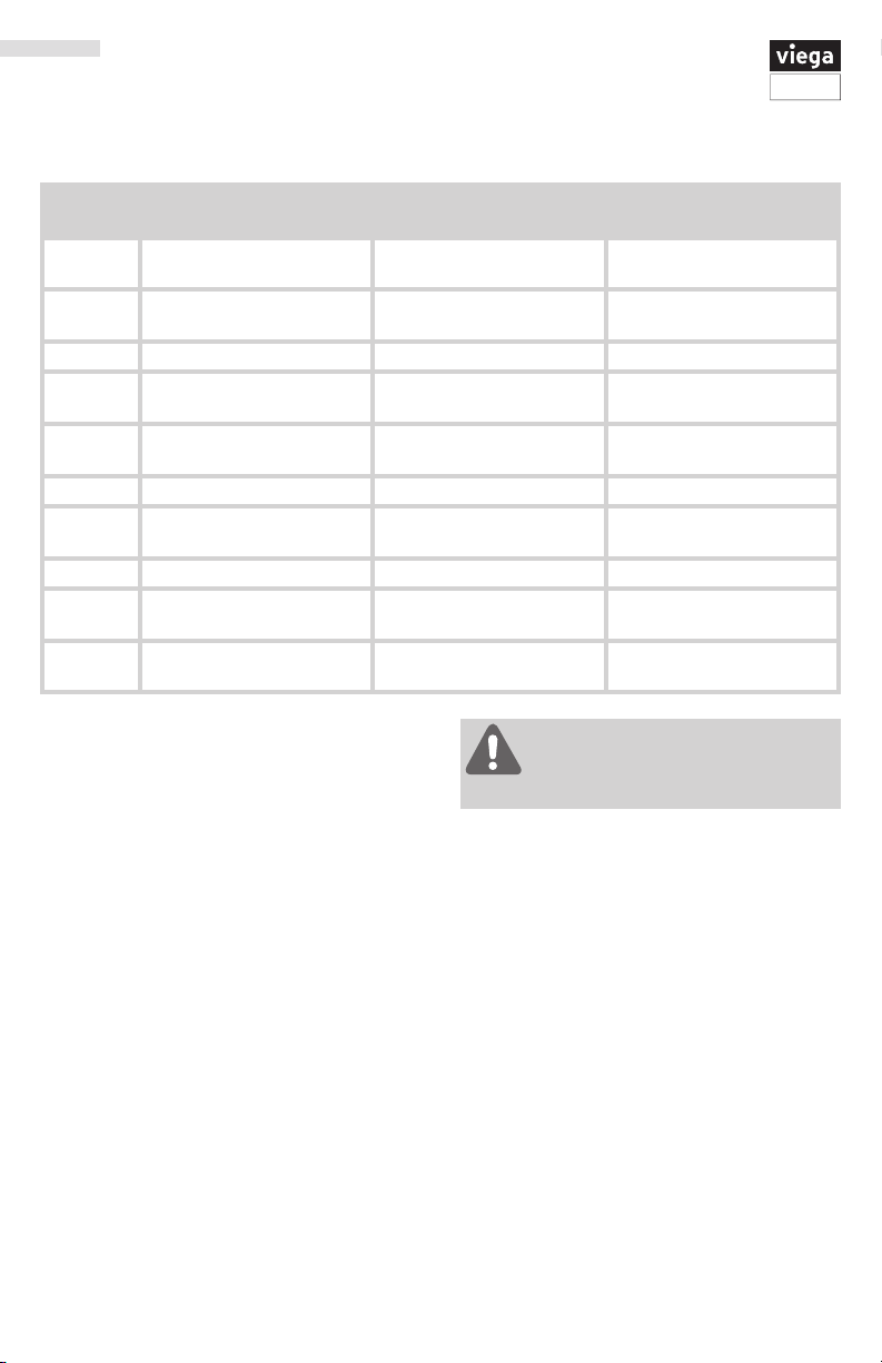
3 Configure the installer options as desired
using the table below.
4 Use the + or - keys to change settings and
the NEXT STEP or PREV STEP key to move
from one option to another.
5 Press DONE key to exit.
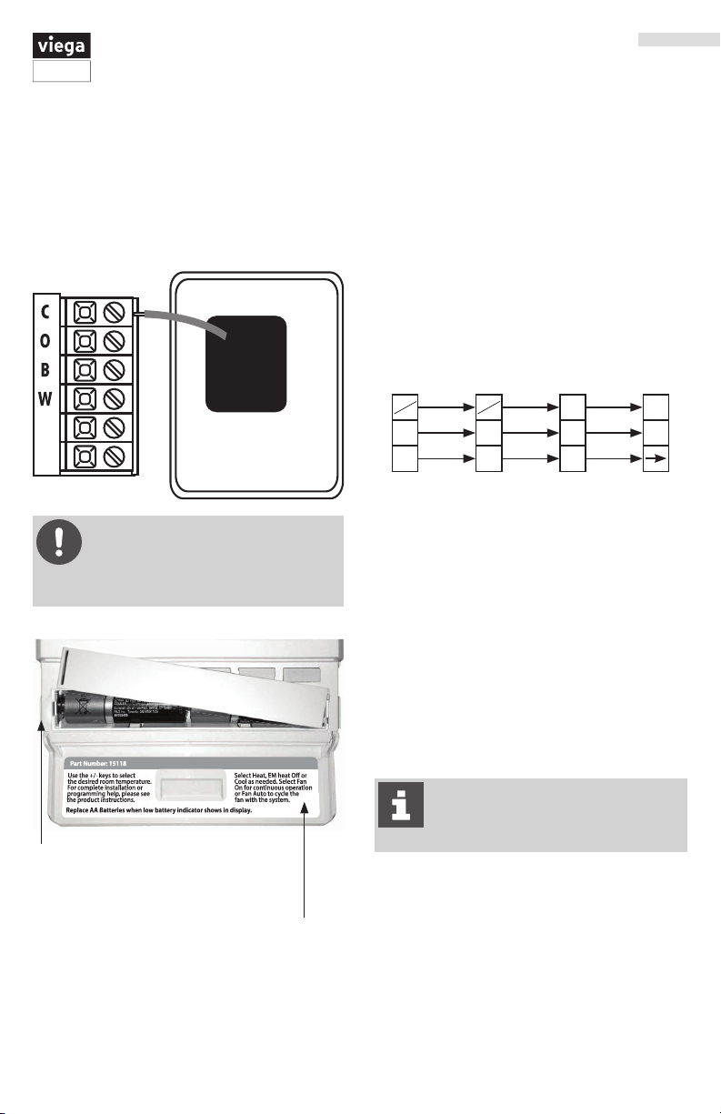
Programming the Thermostat
This thermostat has a technician setup menu
for easy installer conguration. To setup the
thermostat for your particular application:
1 Press MENU button.
2 Press and hold TECH SET button for three
seconds. This three second delay is designed
so that homeowners do not accidentally
access the installer settings.
Only press DONE key when you want
to exit the Technician Setup options.
Technician Setup Steps LCD will Show Adjustment Options Factory
Default
Settings
Filter Change Reminder
This feature will flash FILT in the
display after the elapsed run time to
remind the user to change the filter. A
setting of OFF will disable this feature.
You can adjust the filter
change reminder from
OFF to 2000 hours
of runtime in 50 hour
increments.
Off
Room Temperature Calibration
This feature allows the installer to
change the calibration of the room
temperature display. For example,
if the thermostat reads 70° and you
would like it to read 72° then select +2.
You can adjust the room
temperature display to
read -4°F to +4°F above
or below the factory
calibrated reading.
0°F
Minimum Compressor On Time
This feature allows the installer to
select the minimum run time for the
compressor. For example: A setting
of 4 will force the compressor to run
for at least 4 minutes every time the
compressor turns on, regardless of the
room temperature.
You can select the
minimum compressor
run time from OFF, 3,
4, or 5 minutes. If 3,
4, or 5 is selected, the
compressor will run for
at least the selected
time before turning off.
Off
Compressor Short Cycle Delay
The compressor short cycle delay
protects the compressor from “short
cycling”. This feature will not allow
the compressor to be turned on for 5
minutes after it was last turned off.
Selecting ON will not
allow the compressor
to be turned on for 5
minutes after the last
time the compressor
was on. Select OFF to
remove this delay.
On
Technician Setup Steps
To lock the keypad hold down the +
and – keys for three seconds. You will
see a lock in the display. To unlock
the key pad hold down the + and – keys for
three seconds.