6 of 16
Product
Instructions
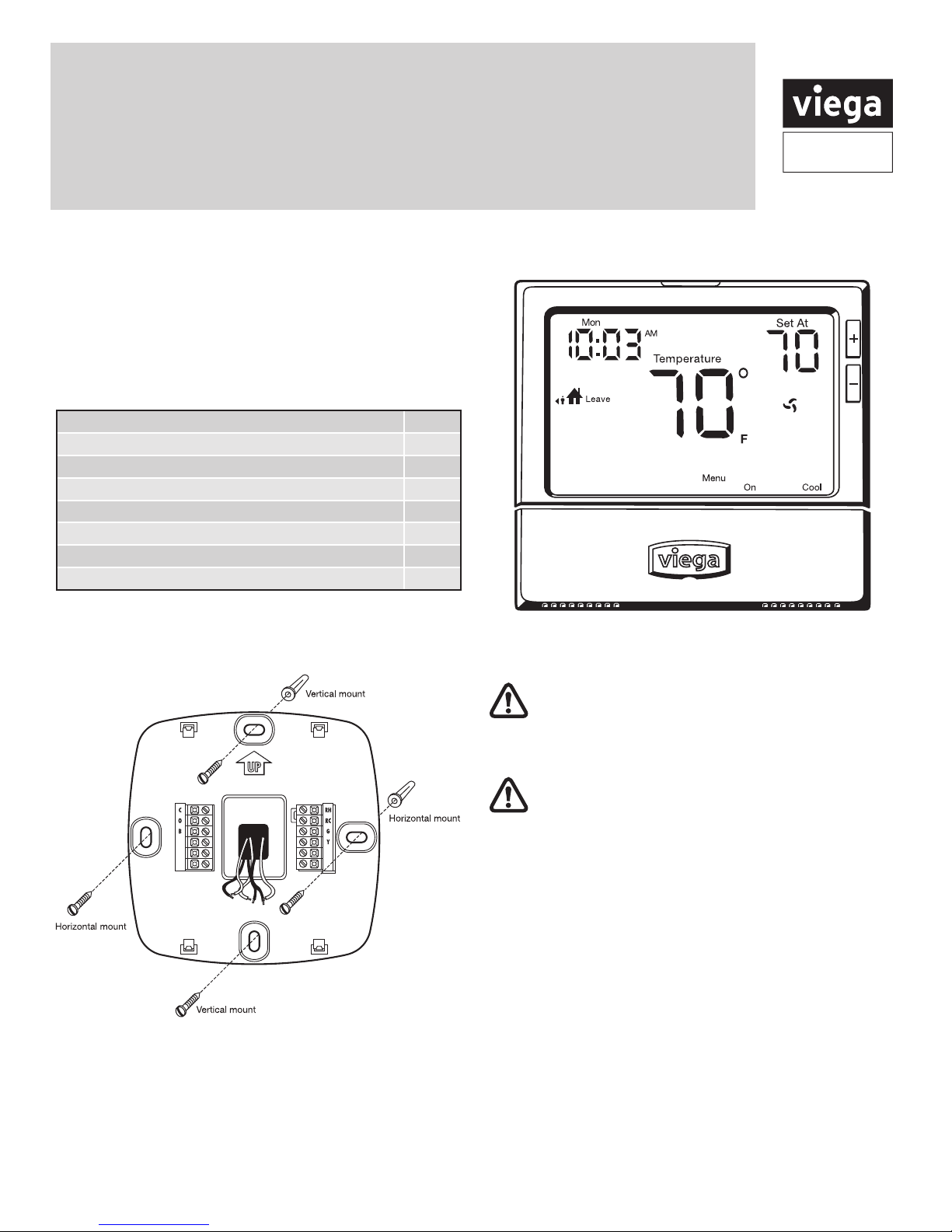
PI-PR 566441 0114 (Multifunctional Thermostat)
Viega LLC, 301 N. Main, 9th Floor • Wichita, KS 67202 • Ph: 800-976-9819 • Fax: 316-425-7618
Class II
Transformer
C
R
120 V AC
Power Supply
N
L
C
O
B
W
RH
RC
G
Y
Thermostat -15116
ViegaViega
Line Voltage
Low Voltage
LEGEND: Zone Controls
Sensors
ELECTRICAL SCHEMATIC
NOTES: Wiring
1. This drawing shows system wiring concept only Installer is responsible for all equipment & detailing required by local codes
2. All wiring shall be in conformance with the latest edition of the National Electrical Code
3. Maximum current rating of Basic and Advance Heating Control Relay is 10 Amps, Basic and Advance Snow Meltng Control
Relay is 5 Amps, Maximum current rating of Zone Control Relays is 5 Amps, if circulator draw exceeds this use pilot relay with
120 VAC coil operated by Viega Control.
4. Consult with control / boiler manufacturer for limitations and installation instructions
5. Do not run the wires parallel to telephone or power cables. If the sensor wires are located in an area with strong sources of
electromagnetic interference (EMI), shielded cable or twisted pair should be used or the wires can be run in a grounded metal
conduit. If using shielded cable, the shield wire should be connected to the Com or Com Sen terminal on the control and not to
earth ground. Use 18 AWG copper wiring for all sensor wiring. Sensors should be located 12" down stream of mixing point.
6. DHW priority relay must be rated to handle full amperage load of zone circulator relay center
7. Other configurations are possible, but all space heating zone circulators must turn off when DHW mode is on or heat source
needs to be sized for multiple loads.
Thermostat &
2 Wire
Powerhead
Class II
Transformer
C
R
120 V AC
Power Supply
N
L
Viega
Red
Red Yellow
Yellow
TO T-T BOILER CONTACT, PUMP
RELAY OR OTHER AUXILIARY
DEVICE REQUIRING CONTACT
CLOSURE. SEE NOTE 2.
C
O
B
W
RH
RC
G
Y
Thermostat -15116
Line Voltage
Low Voltage
LEGEND: Zone Controls
Sensors
ELECTRICAL SCHEMATIC
NOTES: Wiring
1. This drawing shows system wiring concept only Installer is responsible for all equipment & detailing required by local codes
2. All wiring shall be in conformance with the latest edition of the National Electrical Code
3. Maximum current rating of Basic and Advance Heating Control Relay is 10 Amps, Basic and Advance Snow Meltng Control
Relay is 5 Amps, Maximum current rating of Zone Control Relays is 5 Amps, if circulator draw exceeds this use pilot relay with
120 VAC coil operated by Viega Control.
4. Consult with control / boiler manufacturer for limitations and installation instructions
5. Do not run the wires parallel to telephone or power cables. If the sensor wires are located in an area with strong sources of
electromagnetic interference (EMI), shielded cable or twisted pair should be used or the wires can be run in a grounded metal
conduit. If using shielded cable, the shield wire should be connected to the Com or Com Sen terminal on the control and not to
earth ground. Use 18 AWG copper wiring for all sensor wiring. Sensors should be located 12" down stream of mixing point.
6. DHW priority relay must be rated to handle full amperage load of zone circulator relay center
7. Other configurations are possible, but all space heating zone circulators must turn off when DHW mode is on or heat source
needs to be sized for multiple loads.
Thermostat &
4 Wire
Powerhead
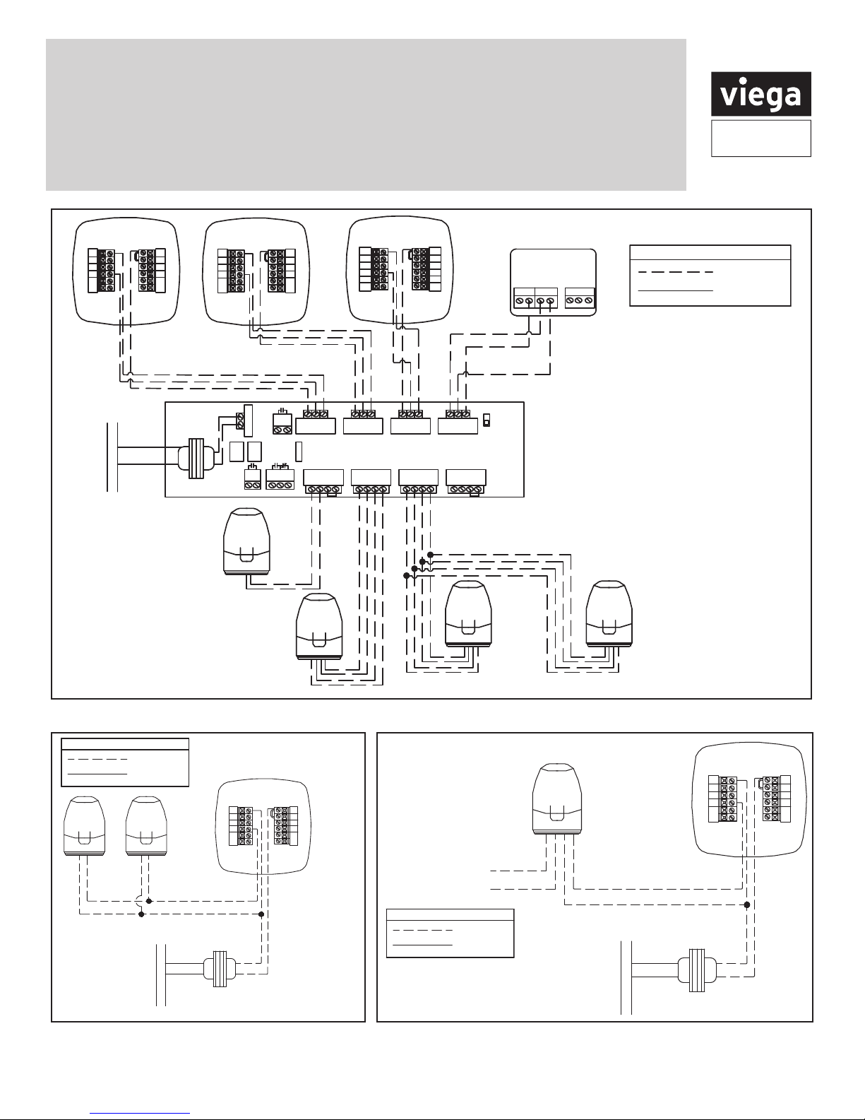
Connecting
Viega
thermostats
to 2 wire
powerheads
Connecting Viega thermostats
to 4 wire powerheads
4 powerheads may
be connected to
each thermostat
4
powerheads
may be
connected
to each
thermostat
ZONE CONTROL (18060, 18062)
WITH OPTIONAL PRIORITY
OFF
ON
ZONE 4 PRIORITY
ZONE 1 ZONE 2 ZONE 3 ZONE 4
ZONE 4 RELAY
N/O N/CCOM
PUMP
END
SWITCH
ISOLATED
END
SWITCH
ZONE 1 ZONE 2 ZONE 3 ZONE 4
FUSE
(5 AMP MAX)
POWER IN
W CR W CR W CR W CR
1 2 3 4
120 V AC
Power Supply
L
N
Viega
Viega
Viega
Yellow
Yellow
Red
Red
Yellow
Yellow
Red
Red
Viega
Yellow
Yellow
Red
Red
R
C
C C R W NTC A/B
Thermostat -18050
POWERHEAD (15061)
FOR USE WITH
STAINLESS MANIFOLD
2 WIRE, 24 V,
POWERHEAD (15064)
FOR USE WITH
STAINLESS MANIFOLD
4 WIRE, 24 V,
JUMPER
3&4 JUMPER
3&4
IF PRIORITY
IS USED
1 2 3 4 1 2 3 4
C
O
B
W
RH
RC
G
Y
Thermostat -15116
C
O
B
W
RH
RC
G
Y
Thermostat -15117
C
O
B
W/E
RH
G
Y
Thermostat -15118
W2 Y2
RC
Line Voltage
Low Voltage
LEGEND: Zone Controls
Sensors
ELECTRICAL SCHEMATIC
NOTES: Wiring
1. This drawing shows system wiring concept only Installer is responsible for all equipment & detailing required by local codes
2. All wiring shall be in conformance with the latest edition of the National Electrical Code
3. Maximum current rating of Basic and Advance Heating Control Relay is 10 Amps, Basic and Advance Snow Meltng Control
Relay is 5 Amps, Maximum current rating of Zone Control Relays is 5 Amps, if circulator draw exceeds this use pilot relay with
120 VAC coil operated by Viega Control.
4. Consult with control / boiler manufacturer for limitations and installation instructions
5. Do not run the wires parallel to telephone or power cables. If the sensor wires are located in an area with strong sources of
electromagnetic interference (EMI), shielded cable or twisted pair should be used or the wires can be run in a grounded metal
conduit. If using shielded cable, the shield wire should be connected to the Com or Com Sen terminal on the control and not to
earth ground. Use 18 AWG copper wiring for all sensor wiring. Sensors should be located 12" down stream of mixing point.
6. DHW priority relay must be rated to handle full amperage load of zone circulator relay center
7. Other configurations are possible, but all space heating zone circulators must turn off when DHW mode is on or heat source
needs to be sized for multiple loads.
Thermostat &
Powerhead
to
Zone Control
Connecting Viega thermostats to
the Viega zone control
Part Numbers:
15116, 15117 and 15118
1. Connect the "RH" terminal
from the thermostat to "R"
terminal on the zone control
2. Connect the "W" terminal
from the thermostat to "W"
terminal on the zone control,
for part number 15118
connect "W/E" terminal from
the thermostat to "W" terminal
on the zone control
3. Connect the "C" terminal from
the thermostat to the "C"
terminal on the zone control
Line Voltage
Low Voltage
Line Voltage
Low Voltage
Line Voltage
Low Voltage
LEGEND: Zone Controls