Viessmann 5056 User manual

Bedienungsanleitung
Operation Manual
5056
H0 Zugschlussbeleuchtung
mit LED, 2 Stück
H0 Train rear lanterns
with LED, 2 pieces
1. Wichtige Hinweise...................................... 2
2. Einleitung.................................................... 2
3. Einbau und Anschluss................................ 3
4. Technische Daten....................................... 4
1. Important information.................................. 2
2. Introduction................................................. 2
3. Mounting and connection............................ 3
4. Technical data............................................. 4

2
DE EN
1. Wichtige Hinweise
Bitte lesen Sie vor der ersten Anwendung des Produktes bzw.
dessen Einbau diese Bedienungsanleitung aufmerksam durch.
Bewahren Sie diese auf, sie ist Teil des Produktes.
Sicherheitshinweise
Vorsicht:
Verletzungsgefahr!
Aufgrund der detaillierten Abbildung des Originals bzw. der
vorgesehenen Verwendung kann das Produkt Spitzen, Kanten
und abbruchgefährdete Teile aufweisen. Für die Montage sind
Werkzeuge nötig.
Stromschlaggefahr!
Die Anschlussdrähte niemals in eine Steckdose einführen!
Verwendetes Versorgungsgerät (Transformator, Netzteil) regel-
mäßig auf Schäden überprüfen. Bei Schäden am Versorgungs-
gerät dieses keinesfalls benutzen!
Alle Anschluss- und Montagearbeiten nur bei abgeschalteter
Betriebsspannung durchführen!
Ausschließlich nach VDE/EN-gefertigte Modellbahntransfor-
matoren verwenden!
Stromquellen unbedingt so absichern, dass es bei einem Kurz-
schluss nicht zum Kabelbrand kommen kann.
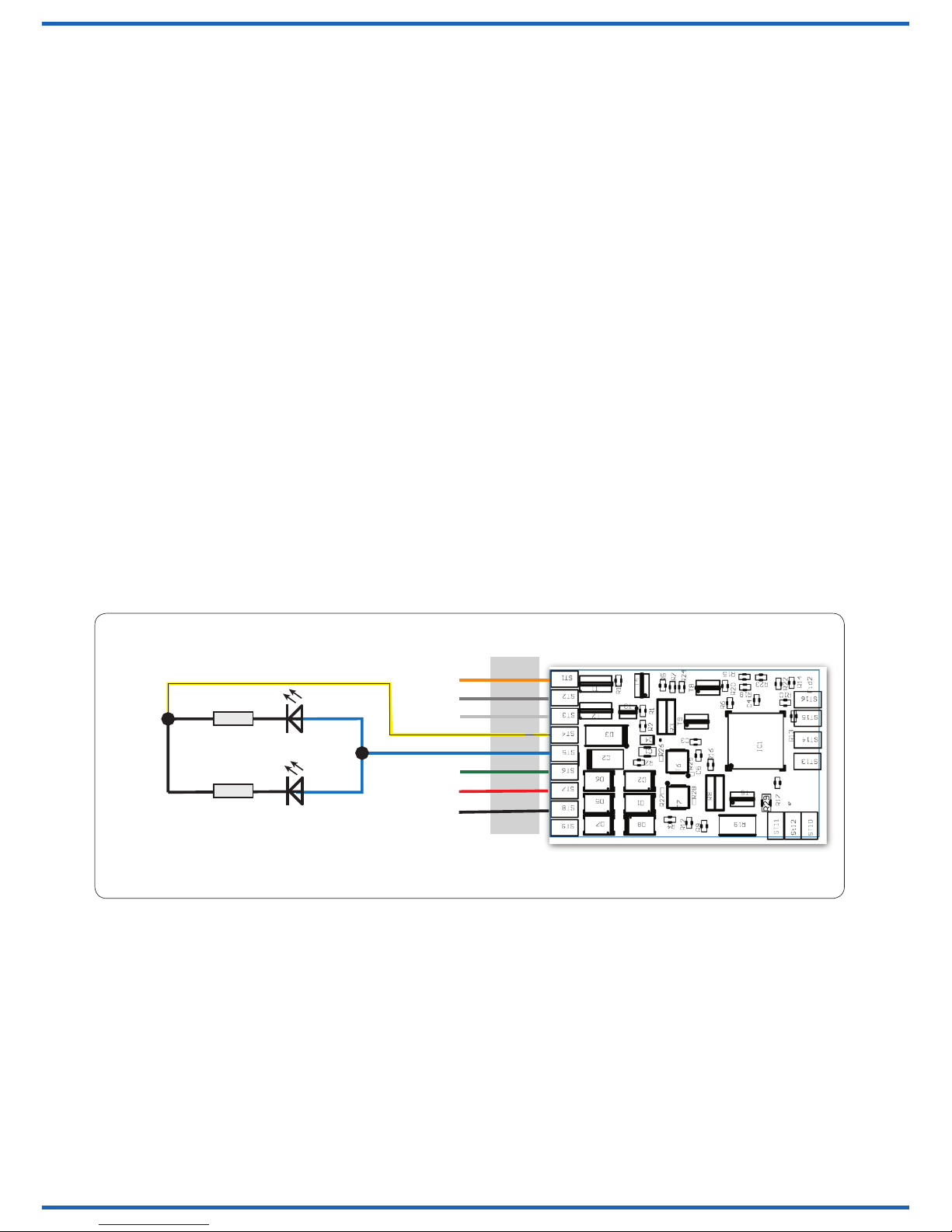
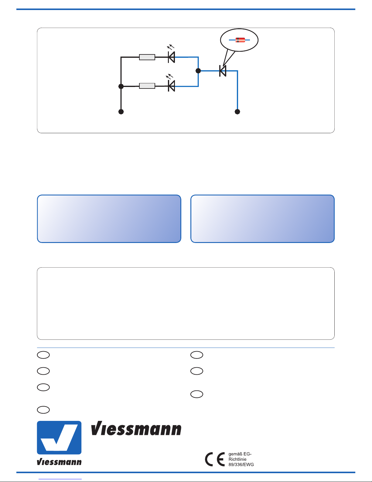
Beiliegende Widerstände und Diode sind für die Funktion er-
forderlich. Keinesfalls beseitigen! Widerstände nicht mit Isola-
tionsmaterial umhüllen, da sonst keine ausreichende Kühlung
möglich ist! Bei Anschluss an die Viessmann Waggonninnenbe-
leuchtung beachten Sie bitte Punkt 3.1.
Das Produkt richtig verwenden
Dieses Produkt ist bestimmt:
- Zum Einbau in Modelleisenbahnwaggons bzw. -wagen.
- Zum Anschluss an einen Modellbahntransformator
(z. B. Art.-Nr. 5200) bzw. an einer Modellbahnsteuerung mit
zugelassener Betriebsspannung.
- Zum Betrieb in trockenen Räumen.
Jeder darüber hinausgehende Gebrauch gilt als nicht bestim-
mungsgemäß. Für daraus resultierende Schäden haftet der
Hersteller nicht.
Packungsinhalt überprüfen
Kontrollieren Sie den Lieferumfang auf Vollständigkeit:
- 2 x rote LED, 1,8 mm, mit ca. 90 mm Kabel
- 2 x Widerstand 6k8
- 1 x Diode
- Anleitung
2. Einleitung
Beachten Sie folgende generelle Hinweise zum Umgang mit
elektrostatisch empndlichen Bauteilen: Arbeiten Sie stets geerdet.
Fassen Sie dazu z. B. kurz die Heizung an. LEDs sind Bauteile, die
als Dioden einen Stromuss nur in eine Richtung, der sog. Fluss-
richtung, zulassen. In umgekehrter Richtung, also der Sperrrich-
tung, müssen die LEDs vor zu hoher Spannung geschützt werden.
Dies macht die beiliegende Diode, sofern keine andere vorgeschal-
tete Elektronik dies übernimmt.
Vorsicht:
Der Betrieb der LEDs ohne passenden Vorwiderstand führt in
der Regel zur Zerstörung der LEDs.
1. Important information
Please read this manual completely and attentively before using
the product for the rst time. Keep this manual. It is part of the
product.
Safety instructions
Caution:
Risk of injury!
Due to the detailed reproduction of the original and the intended
use, this product can have peaks, edges and breakable parts.
For installation tools are required.
Electrical hazard!
Never put the connecting cables into a power socket!
Regularly examine the transformer for damage. In case of any
damage, do not use the transformer!
Make sure that the power supply is switched off when you
mount the device and connect the cables!
Only use VDE/EN tested special model train transformers for
the power supply!
The power sources must be protected to prevent the risk of
burning cables.
Resistors and diode are needed for proper function of the lamp.
Never remove them! Never cover resistors or diode with insu-
lation material, because they have to be cooled by surround-
ing air! For connection to the Viessmann coach lighting please
note point 3.1.
Using the product for its correct purpose
This product is intended:
- For installation in model railroad waggons.
- For connection to an authorized model railroad transformer
(e. g. item-No. 5200).
- For operation in dry rooms only.
Using the product for any other purpose is not approved and is
considered incorrect. The manufacturer is not responsible for any
damage resulting from the improper use of this product.
Checking the package contents
Check the contents of the package for completeness:
- 2 x red LED, 1,8 mm, with 90 mm cable
- 2 x resistor 6k8
- 1 x diode
- Manual
2. Introduction
Please note the following tips for using electrostatically
sensitive components: Work always grounded.
Touch for example the heating for a moment. LEDs are compo-
nents, that admit as diodes a current ow only in one direction, the
so-called ow direction. In reverse direction, the LEDs must be pro-
tected against too high voltage. This is done by the attached diode,
if no other electronics assures this.
Caution:
The operation of the LEDs without suitable series resistor may
destroy the LEDs.

3
Manche Baugruppen enthalten diesen Vorwiderstand bereits, Sie
können die LEDs also direkt an die entsprechend gekennzeich-
neten Lötächen anlöten. Vergewissern Sie sich also stets, ob die
vorgesehene Versorgung der LEDs dafür geeignet ist, die LEDs
ohne externen Vorwiderstand zu betreiben. Möglich ist dies z. B.
bei den Viessmann-Produkten Art.-Nr. 5046, 5049 und 5050 (Wag-
gon-Innenbeleuchtung, analog) sowie 5076, 5077 und 5078 (Wag-
gon-Innenbeleuchtung mit Funktionsdecoder).
3. Einbau und Anschluss
Die blauen Kabel führen an die Anode der LEDs, die schwarzen
somit an die Kathode. Vor dem Einbau auf Funktion prüfen.
3.1 Anschluss an Waggon-Innenbeleuchtung
An die meisten Viessmann-Waggoninnenbeleuchtungen können
die Leuchtdioden direkt angelötet werden. Die zugehörigen Löt-
punkte entnehmen Sie bitte den entsprechenden Anleitungen.
Sollten die Leuchtdioden Ihrer Meinung nach zu hell sein, so kön-
nen Sie die Helligkeit durch die beiliegenden Vorwiderstände redu-
zieren. Die Verwendung der Diode ist hierbei nicht nötig. Bei ande-
ren Produkten entnehmen Sie die Informationen, ob Vorwiderstän-
de enthalten sind, bitte den zugehörigen Anleitungen.
3.2 Anschluss an Lokdecoder oder Funktions-
decoder (Abb. 1)
Die Leuchtdioden lassen sich unter Verwendung der Vorwider-
stände auch an die Licht- oder Funktionsausgänge der Decoder
anschließen. Somit können die LEDs komfortabel ein- oder aus-
geschaltet werden, auch ein Dimmen ist bei geeigneten Decodern
möglich. Schließen Sie dazu die blauen Kabel an die decoderin-
terne Versorgung an und die schwarzen Kabel an die Widerstän-
de 6k8, die Sie dann mit den Funktions- oder Lichtausgängen des
Decoders verbinden. Die Verwendung der Diode ist hierbei nicht
nötig.
Some assemblies already contain this series resistor. You can
solder the LEDs directly to the accordingly marked solder points.
Make always sure whether the intended supply of the LEDs is
suitable to operate the LEDs without external series resistor.
This is possible e. g with the Viessmann item-No. 5046, 5049
and 5050 (coach lighting, analogue) and 5076, 5077 and 5078
(coach lighting with function decoder).
3. Mounting and connection
The blue cables lead to the anode, the black cables lead to the
cathode. Before installation examine for function.
3.1 Connection to coach lighting
Diodes can be soldered directly to most of the Viessmann coach
lightings. Please check the suitable soldering points in the accord-
ing manuals. Should the LEDs shine too bright, you can reduce the
brightness by the attached series resistors. The use of the diode
is not necessary. For other products please refer to the manuals to
clarify, whether series resistors are included.
3.2 Connection to locomotive decoder or
function decoder (g.1)
The LEDs can be connected by using the series resistors, also to
the light outputs or functional outputs of the decoders. Therefore
the LEDs can be switched on or off comfortably. You can also dim
the brightness of the LEDs by suitable decoders. Connect the blue
cables to the intern decoder supply and the black cables to the re-
sistor 6k8 which you then connect to the functional or light outputs
of the decoder. The use of the diode is not necessary.
g. 1Abb. 1
Mot 1
Mot 2
AUX 2
Vers.
AUX 3
Gleis 2
Gleis 1
AUX 4
AUX 1
schwarz/
black blau/
blue
gelb/yellow
2x 6k8
3.3 Anschluss an Radschleifer (Abb. 2)
Bei Zweileitergleisen verbinden Sie zunächst die Seite der Diode,
die keinen Strich hat, mit dem rechten Radschleifer. Die blauen
Kabel der LEDs verbinden Sie mit dem anderen Anschluss der
Diode, der durch den Strich markiert ist.
Mit den schwarzen Kabeln verbinden Sie die Widerstände 6k8,
deren anderes Ende Sie dann mit dem linken Radschleifer
verbinden.
Wenn das Fahrzeug in Fahrtrichtung vorwärts auf den Gleisen
steht, dann leuchtet bei Vorwärtsfahrt die Schlussbeleuchtung,
in entgegengesetzter Fahrtrichtung jedoch nicht.
3.3 Connection to wheel pick up (g. 2)
With 2 rail version, connect the side of the diode which has no
mark, to the right wheel pick up. Connect the blue cables of the
LEDs to the other marked connection of the diode.
With the black cable you connect the resistors 6k8. The other end
of the resistors must be connected to the left wheel pick up.
If the vehicle stands in driving direction on the track, the rear
lanterns will shine when driving forward, the other way not.

Modellbauartikel, kein Spielzeug! Nicht geeignet für Kinder
unter 14 Jahren! Anleitung aufbewahren!
Model building item, not a toy! Not suitable for children
under the age of 14 years! Keep these instructions!
Ce n’est pas un jouet. Ne convient pas aux enfants de
moins de 14 ans ! C’est un produit décor! Conservez cette
notice d’instructions!
Não é um brinquedo!Não aconselhável para menores de
14 anos. Conservar a embalagem.
Modelbouwartikel, geen speelgoed! Niet geschikt voor
kinderen onder 14 jaar! Gebruiksaanwijzing bewaren!
Articolo di modellismo, non è un giocattolo! Non adatto
a bambini al di sotto dei 14 anni! Conservare instruzioni
per l’uso!
Artículo para modelismo ¡No es un juguete! No
recomendado para menores de 14 años! Conserva las
instrucciones de servicio!
DE
EN
FR
NL
IT
ES
PT
Modellspielwaren GmbH
Am Bahnhof 1
D - 35116 Hatzfeld-Reddighausen
www.viessmann-modell.de
g. 2Abb. 2
3.3 Anschluss an Mittelschleifer
Die Verdrahtung der Bauteile erfolgt wie bei der Zweileiterversion,
nur wird jetzt die Seite der Diode, die keine Markierung hat,
an den Mittelleiter angeschlossen.
Allerdings leuchtet hier die Zugschlussbeleuchtung immer,
unabhängig von der Fahrtrichtung.
3.3 Connection to pick up shoe
The wiring of the components is according to the 2 rail version.
But now the side of the diode which has no mark is connected to
the third rail.
However the rear lanterns always shine, independent from driving
direction.
schwarz/
black blau/
blue
2x 6k8
Radschleifer links
left wheel pick-up
Radschleifer rechts
right wheel pick-up
Die aktuelle Version der Anleitung nden Sie auf der
Viessmann Homepage unter der Artikelnummer.
The latest version of the manual can be looked up at the
Viessmann homepage entering the item-No.
4. Technical data
Maximum continuous current: 30 mA
Typical forward voltage: ca. 2 V
Diameter: 1,8 mm
Dimensions of housing base: ca. 2,4 mm x 3,3 mm
4. Technische Daten
Maximaler Dauerstrom: 30 mA
Typische Durchlassspannung: ca. 2 V
Durchmesser: 1,8 mm
Maße Gehäuseunterteil: ca. 2,4 mm x 3,3 mm
87903
Stand 01/sw
04/2015
Ch/Me
4
Notes
Notizen
Table of contents
Other Viessmann Cables And Connectors manuals

Viessmann
Viessmann 4565 H0 User manual

Viessmann
Viessmann 3560 User manual

Viessmann
Viessmann 5048 H0 User manual

Viessmann
Viessmann CAR motion 8430 User manual

Viessmann
Viessmann 6049 User manual

Viessmann
Viessmann 4560 User manual

Viessmann
Viessmann 2320 User manual

Viessmann
Viessmann 9565 0 User manual

Viessmann
Viessmann 4558 User manual
Popular Cables And Connectors manuals by other brands

National Instruments
National Instruments 9923 USER GUIDE AND SPECIFICATIONS

Philips
Philips MODEL NAME SWA2109 Specifications

Staubli
Staubli PV-KST4/13II-UR Assembly instructions

Kohler
Kohler 15-60REOZK installation instructions

Dietz
Dietz 66145 instruction manual

Foxun
Foxun SX-SP144E-HD4K2K operating instructions