manuals.online logo
Brands
  1. Home
  2. •
  3. Brands
  4. •
  5. Viessmann
  6. •
  7. Cables And Connectors
  8. •
  9. Viessmann 5048 H0 User manual

Viessmann 5048 H0 User manual

Viessmann
Modellspielwaren GmbH
Am Bahnhof 1
D - 35116 Hatzfeld (Eder)
www.viessmann-modell.de
5048 H0
Stromführende Kupplungen
zweipolig, 2 Stück
Conducting couplers
2 pole, 2 pieces
Bedienungsanleitung
Operation Manual
Modellbauartikel, kein Spielzeug! Nicht geeignet für
Kinder unter 14 Jahren! Anleitung aufbewahren!
Model building item, not a toy! Not suitable for children
under the age of 14 years! Keep these instructions!
Ce n’est pas un jouet. Ne convient pas aux enfants de
moins de 14 ans ! C’est un produit décor! Conservez
cette notice d’instructions!
Modelbouwartikel, geen speelgoed! Niet geschikt voor
kinderen onder 14 jaar! Gebruiksaanwijzing bewaren!
Articolo di modellismo, non è un giocattolo! Non
adatto a bambini al di sotto dei 14 anni! Conservare
instruzioni per l’uso!
Artículo para modelismo. No es un juguete! No
recomendado para menores de 14 años! Conserva las
instrucciones de servicio!
Não é um brinquedo! Não aconselhável para menores
de 14 anos. Conservar a embalagem.
DE
EN
FR
NL
IT
ES
PT
DE
1. Wichtige Hinweise
Bitte lesen Sie vor der ersten Anwendung des Produktes bzw.
dessen Einbau diese Bedienungsanleitung aufmerksam durch
und bewahren Sie sie auf. Sie ist Teil des Produktes.
Sicherheitshinweise
Vorsicht:
Stromschlaggefahr!
Die Anschlussdrähte niemals in eine Steckdose einführen!
Verwendetes Versorgungsgerät (Transformator, Netzteil)
regelmäßig auf Schäden überprüfen. Bei Schäden am
Versorgungsgerät dieses keinesfalls benutzen!
Alle Anschlussarbeiten nur bei abgeschalteter Betriebs-
spannung durchführen! Stromquellen so absichern, dass
es im Falle eines Kurzschlusses nicht zum Kabelbrand
kommen kann. Nur handelsübliche und VDE-geprüfte
Modellbahntransformatoren verwenden!
Packungsinhalt überprüfen
Kontrollieren Sie den Lieferumfang auf Vollständigkeit:
- 2 stromführende Kupplungen,
- diese Anleitung.
Das Produkt richtig verwenden
Dieses Produkt ist bestimmt:
- Zum Einbau in H0 Modelleisenbahn-Waggons unter
Beachtung der für dieses Produkt geltenden
Verarbeitungshinweise.
- Zum Betrieb mit einer Betriebsspannung von maximal
24 V =/~.
- Zum Betrieb in trockenen Räumen.
Jeder darüber hinausgehende Gebrauch gilt als nicht
bestimmungsgemäß. Für daraus resultierende Schäden
haftet der Hersteller nicht.
2. Einleitung
Die stromführenden Kupplungen sind modizierte Fleisch-
mann-PROFI-Kupplungen 6515 und weisen daher die
gleichen Eigenschaften auf, z. B. normales Entkuppeln und
Vorentkuppeln.
Es sind Steckkupplungen für alle Fahrzeuge mit NEM 362-
Aufnahmeschacht.
1
Die aktuelle Version der Anleitung nden Sie auf
der Viessmann-Homepage unter der Artikelnummer.
The latest version of the manual can be looked up at the
Viessmann homepage using the item-No.
92145
Stand 02/sw
10/2014
Ho/Me
4
Abb. 1 Fig. 1
rechter Radschleifer
bzw. Mittelschleifer
right wheel pick-up
resp. center pick-up
Lokomotive
Locomotive
linker Radschleifer
bzw. Chassis
left wheel pick-up
resp. chassis ground
Waggon ohne
Beleuchtung
Car without
lighting
Lötverbindungen
Soldering connections
Waggon-
Innenbeleuchtung
z. B. 50492
Interior lighting set
e. g. 50492
4. Trouble-Shooting
There is no current transferred from one coupler to the other.
Possible reasons are:
- The wire brackets of the couplers are bent.
Adjust the wires.
- The connecting cables are pulled off or not properly
soldered.
Check all connections.
If you cannot nd the cause of the fault send the couplers to
Viessmann.
5. Technical data
Permitted voltage: 24 V ~/= maximum
(also for digital supply)
Maximum current: 1 A maximum
Suitable for vehicles with NEM pocket (NEM 362).
Fleischmann ist ein eingetragenes Warenzeichen der / is
a registered trademark of Gebr. Fleischmann GmbH & Co.
KG, Nürnberg.
ENDE
In die Kupplungen sind Drahtbügel integriert. Über den bzw.
die Drahtbügel erfolgt die Stromübertragung von einem zum
anderen Modellbahnfahrzeug.
Der stromübertragende Drahtbügel stabilisiert außerdem die
Höhenlage der Kupplung. Dadurch wird ein unbeabsichtigtes
Abkuppeln an Steigungsübergängen verhindert.
3. Einbau
Prüfen Sie, ob die Kupplungen beschädigt sind, insbesondere
ob Drahtbügel und Anschlusskabel korrekt befestigt sind.
Sollten Sie Schäden feststellen, senden Sie die Kupplungen
zum Umtausch ein.
Die Steckkupplung ist für den Einbau in Fahrzeuge mit
genormtem Kupplungsschacht nach NEM 362 vorgesehen.
Tauschen Sie die vorhandene Kupplung gegen die stromfüh-
rende Kupplung aus.
Nach dem Austausch der Kupplung führen Sie das/die
Anschlusskabel in den Waggon.
Vorsicht:
Die Beweglichkeit von Drehgestellen darf durch die
Anschlusskabel nicht behindert werden!
Schließen Sie den gewünschten Verbraucher an (z. B. eine
Waggon-Innenbeleuchtung von Viessmann nach Abb. 1).
Beachten Sie dabei die Angaben des Herstellers des jeweili-
gen Verbrauchers.
Vorsicht:
Es dürfen max. 1 A Strom pro Kontakt durch die Kupplung
geführt werden. Werden mehrere Verbraucher von einer
Stelle aus versorgt, müssen Sie den Stromverbrauch aller
angeschlossenen Verbraucher zusammenzählen.
Vorzugsweise wird der Strom von den Stromschleifern der
Lokomotive abgenommen und über deren Kupplung durch den
Zug geleitet. Benden sich Waggons ohne Stromverbraucher
im Zugverband, so sind auch diese mit stromführenden Kupp-
lungen auszustatten. Die Kabel beider Kupplungen werden
dann einfach nur paarweise miteinander verbunden (jeweils
ein Kabel der einen Kupplung mit einem Kabel der anderen
Kupplung).
4. Fehlersuche und Abhilfe
Die Stromübertragung über die Kupplung funktioniert nicht.
Mögliche Ursachen:
- Der zur Stromübertragung vorgesehene Drahtbügel ist
verbogen:
Justieren Sie den Drahtbügel vorsichtig nach.
- Die Anschlusskabel sind nicht korrekt angelötet oder
abgerissen:
Überprüfen Sie die Anschlüsse.
Wenn Sie die Fehlerursache nicht lokalisieren können, senden
Sie die Kupplungen zur Reparatur ein.
5. Technische Daten
Betriebsspannung: max. 24 V =/~
(auch für Digitalspannung)
durchleitbarer Strom: 1 A maximal
für Fahrzeuge mit Kupplungsschacht nach NEM 362.
1. Important information
Please read this manual completely and attentively before
using the product for the rst time. Keep this manual. It is part
of the product.
Safety information
Caution:
Electrical hazard!
Never put the connecting wires into a power socket! Regu-
larly examine the transformer for damage. In case of any
damage, do not use the transformer!
Installation and electrical wiring may only be carried out
while the power supply is switched off. Only use transfor-
mers compliant with VDE / EN standards.
Checking the package contents
Check the contents of the package for completeness:
- 2 pieces conducting couplers,
- this manual.
Using the product for its correct purpose
This product is intended:
- For mounting into a H0 model railway car, you must obey
the following instructions.
- For operation with a power supply up to 24 V ~/=.
- For operation in dry rooms only.
Using the product for any other purpose is not approved and
is considered incorrect. The manufacturer is not responsible
for any damage resulting from the improper use of this
product.
2. Introduction
The conducting couplers are modied Fleischmann-PROFI
couplers 6515.
They have a shaft matching the pocket as per NEM 362.
There are small wires integrated into the couplers that make
contact and transmit current from one vehicle to the next.
The couplers have all the features of the Fleischmann-PROFI
couplers such as normal un-coupling and delayed un-coupling.
The electrical wire also serves as a stabilizer in the vertical.
Thus unintended un-coupling at the start of a gradient is
prevented.
3. Mounting
Inspect the coupler heads and particularly the wires and ca-
bles. Should there be any damage return the entire package
for a replacement.
These couplers are designed for cars and locomotives with
standardised coupler pockets as per NEM 362. Exchange the
existing couplers against the conducting ones.
Then feed the wires into the railway car. Pay attention to the
fact that the bogies have to move freely and must not be
touched by the wires!
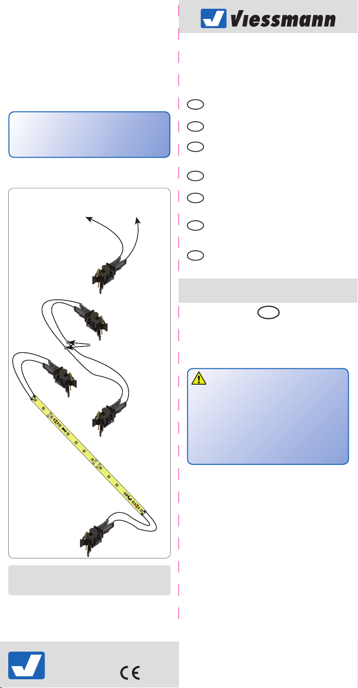
Connect the load (e. g. Viessmann interior lighting set as per
g. 1). Please also refer to the instructions of the supplier of
the respective load.
Caution:
The couplers can carry a maximum current of 1 A per cont-
act. If several loads are powered from one source you have
to add the current draw of all loads.
Generally the current would be fed via the couplers from the
wheel pick-ups of the locomotive through the train. If cars
without electric loads are part of the train they also have to
be equipped with conducting couplers. The cables of both
couplers are then connected to provide through wiring (one
cable from one coupler to the other and the same with the
second cable).
32

Other Viessmann Cables And Connectors manuals

Viessmann 4560 User manual

Viessmann

Viessmann 4560 User manual

Viessmann 5056 User manual

Viessmann

Viessmann 5056 User manual

Viessmann 3560 User manual

Viessmann

Viessmann 3560 User manual

Viessmann 9565 0 User manual

Viessmann

Viessmann 9565 0 User manual

Viessmann 4558 User manual

Viessmann

Viessmann 4558 User manual

Viessmann 6049 User manual

Viessmann

Viessmann 6049 User manual

Viessmann 2320 User manual

Viessmann

Viessmann 2320 User manual

Viessmann 4565 H0 User manual

Viessmann

Viessmann 4565 H0 User manual

Viessmann CAR motion 8430 User manual

Viessmann

Viessmann CAR motion 8430 User manual

Popular Cables And Connectors manuals by other brands

Viking CKVBI installation guide

Viking

Viking CKVBI installation guide

Philips SWV2946T Specifications

Philips

Philips SWV2946T Specifications

Philips SWV3800 Specifications

Philips

Philips SWV3800 Specifications

Cypress CLUX-8M Operation manual

Cypress

Cypress CLUX-8M Operation manual

Sumitomo Lynx-Custom Fit Splice-On Connector installation manual

Sumitomo

Sumitomo Lynx-Custom Fit Splice-On Connector installation manual

Philips SWA3303W Specifications

Philips

Philips SWA3303W Specifications

Electric Eel 5/8" & 3/4" Diameter Tri-Max Repair operation manual

Electric Eel

Electric Eel 5/8" & 3/4" Diameter Tri-Max Repair operation manual

DOREMIDI MTC-10 instructions

DOREMIDI

DOREMIDI MTC-10 instructions

Philips SWV3135S/10 user manual

Philips

Philips SWV3135S/10 user manual

Omron XS5H installation instructions

Omron

Omron XS5H installation instructions

LumX LM 84015 instruction manual

LumX

LumX LM 84015 instruction manual

Tripp Lite N356-01M Specification sheet

Tripp Lite

Tripp Lite N356-01M Specification sheet

Phase3 Powersafe Assembly guide

Phase3

Phase3 Powersafe Assembly guide

Rocket Fish RF-G1603 Quick setup guide

Rocket Fish

Rocket Fish RF-G1603 Quick setup guide

Tripp Lite N352-05M Specification sheet

Tripp Lite

Tripp Lite N352-05M Specification sheet

Cable-Tronix CT-VGA/HD-CONV-V2 user manual

Cable-Tronix

Cable-Tronix CT-VGA/HD-CONV-V2 user manual

AVLink DPS-4 user manual

AVLink

AVLink DPS-4 user manual

Tripp Lite F009-006 Specification sheet

Tripp Lite

Tripp Lite F009-006 Specification sheet

manuals.online logo
manuals.online logoBrands
  • About & Mission
  • Contact us
  • Privacy Policy
  • Terms and Conditions

Copyright 2025 Manuals.Online. All Rights Reserved.