manuals.online logo
Brands
  1. Home
  2. •
  3. Brands
  4. •
  5. VIETA
  6. •
  7. Car Stereo System
  8. •
  9. VIETA VPC45BT User manual

VIETA VPC45BT User manual

Other manuals for VPC45BT

1

Other VIETA Car Stereo System manuals

VIETA CCM4000R User manual

VIETA

VIETA CCM4000R User manual

VIETA VTC2500BT User manual

VIETA

VIETA VTC2500BT User manual

VIETA VPC55BT User manual

VIETA

VIETA VPC55BT User manual

VIETA VPC450BT User manual

VIETA

VIETA VPC450BT User manual

VIETA VNT7800BT User manual

VIETA

VIETA VNT7800BT User manual

VIETA VPC350R User manual

VIETA

VIETA VPC350R User manual

VIETA CDV7500GP User manual

VIETA

VIETA CDV7500GP User manual

VIETA VPC35R User manual

VIETA

VIETA VPC35R User manual

VIETA CDV7200BT User manual

VIETA

VIETA CDV7200BT User manual

VIETA VPC550R User manual

VIETA

VIETA VPC550R User manual

VIETA CDV7000BT User manual

VIETA

VIETA CDV7000BT User manual

VIETA VTC1000R User manual

VIETA

VIETA VTC1000R User manual

VIETA VPC66BT User manual

VIETA

VIETA VPC66BT User manual

VIETA VTC4000BT User manual

VIETA

VIETA VTC4000BT User manual

VIETA VTC2000BT User manual

VIETA

VIETA VTC2000BT User manual

VIETA VPC750BT User manual

VIETA

VIETA VPC750BT User manual

Popular Car Stereo System manuals by other brands

Sony CDXM60UI - Marine CD Receiver MP3/WMA/AAC... Features

Sony

Sony CDXM60UI - Marine CD Receiver MP3/WMA/AAC... Features

Philips CED780/98 quick start guide

Philips

Philips CED780/98 quick start guide

Becker Online Pro 7800 installation guide

Becker

Becker Online Pro 7800 installation guide

JVC KD-LH810 instructions

JVC

JVC KD-LH810 instructions

Clarion PU-9836A Service manual

Clarion

Clarion PU-9836A Service manual

Sony RM-X7BT reference guide

Sony

Sony RM-X7BT reference guide

Mitsubishi Electric AR0M manual

Mitsubishi Electric

Mitsubishi Electric AR0M manual

Insignia NS-HD5113 user guide

Insignia

Insignia NS-HD5113 user guide

Clarion BTD3341 user manual

Clarion

Clarion BTD3341 user manual

USA SPECS PA11-VW6 owner's manual

USA SPECS

USA SPECS PA11-VW6 owner's manual

Sony MEX-N4380BT operating instructions

Sony

Sony MEX-N4380BT operating instructions

Kenwood KCD-BT6544U/UY Service manual

Kenwood

Kenwood KCD-BT6544U/UY Service manual

JVC KD-DB912BT instruction manual

JVC

JVC KD-DB912BT instruction manual

Philips CSQ405/98 user manual

Philips

Philips CSQ405/98 user manual

Alpine TDM-7544 Specifications

Alpine

Alpine TDM-7544 Specifications

JL Audio Stealthbox SB-CAN-G2MVX3D/10TW3 installation guide

JL Audio

JL Audio Stealthbox SB-CAN-G2MVX3D/10TW3 installation guide

Denso TEN FT0108A user manual

Denso TEN

Denso TEN FT0108A user manual

Pyle PLD57MU owner's manual

Pyle

Pyle PLD57MU owner's manual

manuals.online logo
manuals.online logoBrands
  • About & Mission
  • Contact us
  • Privacy Policy
  • Terms and Conditions

Copyright 2025 Manuals.Online. All Rights Reserved.

CDE VERSION
E - 1
1. NOTE OF DISCS
MOISTURE CONDENSATION
NOTES ON CDs
P. 2
P. 3
P. 4
P. 1
P. 5
P. 6
P. 7
1.
2.
3.
4.
5.
NOTES ON DISCS
There are paste residue.
Ink is sticky (P.5).
Stickers that are beginning
to peel away, leaving a
sticky residue (P.6).
Labels are attached (P.7).
On a rainy day or in a very damp area, moisture may condense on the lenses inside the unit.
Should this occur, the unit will not operate properly. In such a case, remove the disc and wait for
about an hour until the moisture has evaporated.
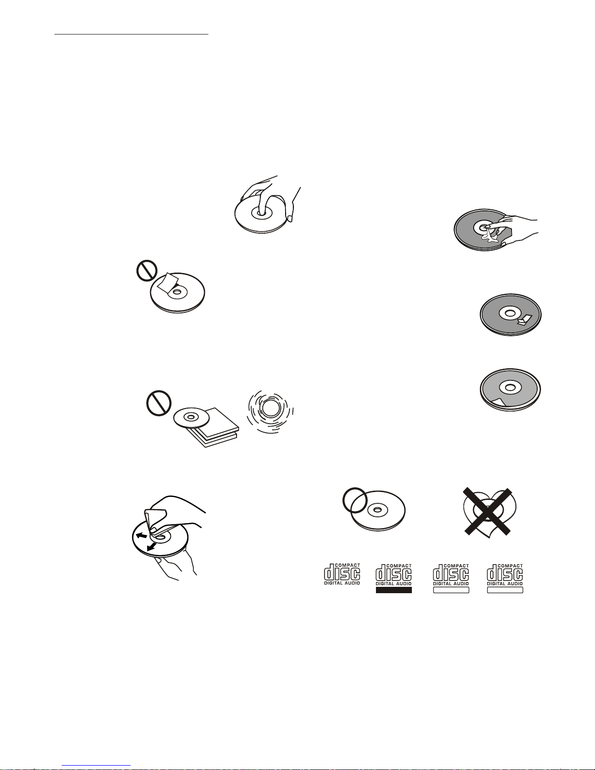
A dirty or defective disc may cause sound
dropouts while playing. To enjoy optimum
sound, handle the disc as follows.
Handle the disc by its edge. To keep the disc
clean, do not touch the surface (P.1).
If you use the discs explained below, the
sticky residue can cause the CD to stop
spinning and may cause malfunction or ruin
your discs.
Do not use second-hand or rental CDs that
have a sticky residue on the surface (for
example, from peeled-off stickers or from
ink, or glue leaking from under the stickers).
Do not stick paper or tape on the disc (P.2).
Before playing, clean the discs with an
optional cleaning cloth. Wipe each disc from
the centre out (P.4).
Do not use solvents such as benzine,
thinner,commercially available cleaners, or
antistatic spray intended for analog discs.
Do not expose the discs to direct sunlight or
heat sources such as hot air-ducts, or leave
them in a car parked in direct sunlight where
there can be a considerable rise in
temperature inside the car (P.3).
Do not use rental CDs with old labels that
are beginning to peel off.
Do not use your CDs with labels or stickers
attached.
**************
*******
*******
*******
*******
*******
*******
*******
*******
****
*******
******* *******
*******
Do Not Use Special Shape CDs
Be sure to use round shape CDs only for
this unit and do not use any special shape
CDs. Use of special shape CDs may cause
the unit to malfunction.(P.8).
Be sure to use CDs with disc mark
Only for this unit.
RECORDABLE
REWRITABLE
P. 8
CD-Rs and CD-RWs which have not
undergone finalization processing cannot
be played. (For more information on
finalization processing, refer to the manual
for your CD-R/CD-RW writing software or
CD-R/CD-RW recorder.) Additionally,
depending on the recording status, it may
prove impossible to play certain CDs
record on CD-R or CD-RW.
TEXT
2. INSTALLATION
Before finally installing the unit, connect the wiring temporarily and make sure it is all connected
up properly and the unit and system work properly.
Use only the parts included with the unit to ensure proper installation. The use of unauthorized
parts can cause malfunctions.
Consult with your nearest dealer if installation requires the drilling of holes or other
modifications of the vehicle.
Install the unit where it does not get in the driver's way and cannot injure the passenger if there is
a sudden stop, like an emergency stop.
If installation angle exceeds 30ー from horizontal, the unit might not give its optimum
performance.
Avoid installing the unit where it would be subject to high temperature, such as from direct
sunlight, or from hot air, from heater, or where it would be subject to dust dirt or excessive
vibration.
Be sure to remove the front panel before installing the unit.
DIN FRONT/REAR-MOUNT
This unit can be property installed either from “Front” (conventional DIN Front-mount) or “Rear”(DIN
Rear-mount installation, utilizing threaded screw holes at the sides of the unit chassis). For details,
refer to the following illustrated installation methods A and B.
DIN FRONT-MOUNT (Method A)
Installation the unit
1. Dashboard
2. Holder
After inserting the half sleeve into the
dashboard, select the appropriate tab
according to the thickness of the
dashboard material and bend them
inwards to secure the holder in place.
3. Screw
1
7
4
23
5
61. Dashboard
2. Nut (5mm)
3. Spring washer
4. Screw (4x12mm)
5. Screw
6. Support Strap
Be sure to use the support strap to secure
the back of the unit in place. The strap can
be bent by hand to the desired angle.
7. Plain washer
182
53
12
3
E - 2
DIN REAR-MOUNT (METHOD B)
Installation using the screw holes on the sides of the unit.
Fastening the unit to the factory radio mounting bracket.
1. Select a position where the screw
holes of the bracket and the screw
holes of the main unit become
aligned (are fitted) and tighten the
screws at 2 places on each side.
2. Screw
3. Factory radio mounting bracket.
4. Dashboard or Console
5. Hook (Remove this part)
Note: the mounting box, outer trim ring,
and half-sleeve are not used for method
B installation.
5
2
4
3
25
a. Frame
b. Insert fingers into the groove in the
front of frame and pull out to remove
the frame. (When re-attaching the
frame, point the side with a groove
down wards and attach it.)
c. Insert the levers supplied with the
unit into the grooves at both sides of
the unit as shown in figure until they
click. Pulling the levers makes it
possible to remove the unit from the
dashboard.
Trim Plate Installation:
Push the trim plate against the chassis until it is fitted.
You must do this before you install the front panel, otherwise it can't be attached.
Removing the unit
a
b
c
E - 3
3. DETACHABLE CONTROL PANEL (D.C.P.)
Removing The Detachable Control Panel (D.C.P.).
1. Turn the power off
2. Press the D.C.P. release button
3. Remove the D.C.P.
PANEL RELEASE
BUTTON
B
A
2
Attaching the DCP
CAUTION
1. Attach the panel at the right side first, with
point B on the main unit touching point A on the
D.C.P. (As shown on the diagram).
2. Then press the left side of D.C.P. onto the main
unit until a “click” sound is heard.
DO NOT insert the D.C.P from the left side. Doing so may damage it.
The D.C.P can easily be damaged by shocks. After removing it, place it in a protective case and be careful not
to drop it or subject it to strong shocks.
When the release button is pressed and the D.C.P is unlocked, the car's vibrations may cause it to fall. To
prevent damage to the D.C.P, always store it in a protective case after detaching it.
The rear connector that connects the main unit and the D.C.P is an extremely important part. Be careful not to
damage it by pressing on it with fingernails, pens, screwdrivers, etc.
Note:
If the D.C.P is dirty, wipe off the dirt with soft,
dry cloth only. And use a cotton swab soaked
in isopropyl alcohol to clean the socket on the
back of the D.C.P.
Socket
T
RESE
RESETTING THE UNIT:
After releasing the front panel, use a pencil or any non-metalic object to press & hold the
reset button for five seconds to reset the unit.
E - 4
R-CH
L-CH
AMP
4. WIRING DIAGRAM (20 PIN + ISO + SMALL CONNECTOR)
FUSE
20-PIN
AUDIO/POWER
HARNESS
(See Figure 1)
2
2
4
4
6
6
8
8
1
1
3
3
5
5
7
7
8
8
6
6
5
5
7
7
4
4
3
3
2
2
1
1
ISO CONNECTOR WIRING CHART
POWER ANTENNA
FUNCTION/LABEL
BATTERY(+)
GROUND
IGNITION(ACC)
RIGHT REAR SPEAKER (+)
RIGHT FRONT SPEAKER (+)
LEFT FRONT SPEAKER (+)
LEFT REAR SPEAKER (+)
LEFT FRONT SPEAKER (-)
RIGHT FRONT SPEAKER (-)
LEFT REAR SPEAKER (-)
RIGHT REAR SPEAKER (-)
B2
B8
B7
B6
B5
B4
B3
A5
A4
PIN
B1
A8
A7
VIOLET/BLACK
WHITE
GREY
GREEN
GREEN/BLACK
WHITE/BLACK
GREY/BLACK
YELLOW
WIRE COLOR
BLACK
VIOLET
RED
BLUE
ISO CONNECTOR 4PIN+8PIN
FEMALE WITH MALE TERMINAL
CONNECTOR A
CONNECTOR B
Figure 1
(See Figure 1)
ISO
CONNECTOR
E - 5
Ignition wire
(RED)
Battery wire
(YELLOW)
Battery wire
(YELLOW)
Ignition wire
(RED)
Battery wire
(YELLOW)
Unit
Unit
Ignition wire
(RED)
Unit
1 PIN (RED)
Vehicle
3 PIN(YELLOW)
3 PIN(YELLOW)
1 PIN (RED)
Vehicle
3 PIN(YELLOW)
Vehicle
1 PIN (RED)
WARNING Connecting the ISO Connector
The pin arrangement for the ISO connectors depends on the type of vehicle you
drive.Make sure to make the proper connections to prevent damage to the unit.
The default connection for the wiring harness is described in below. If the ISO
connector pins are set as described in or .make the connection as illustrated.
23
1
The 1 pin (red) of the vehicle's ISO connector is connected to the constant power
supply, and the 3 pin (yellow) is linked to the ignition.
2
The 3 pin (yellow) of the vehicle's ISO connector is not connected to anything,
while the 1 pin (red) is connected to the constant power supply (or both the 1(red)
and 3(yellow)pins are connected to the constant power supply).
3
(Default setting) The 1 pin (red) of the vehicle's ISO connector is linked with
the ignition,and the 3 pin (yellow) is connected to the constant power supply.
1
When the connection is made as in above,the unit's power will not be linked to the
ignition key. For that reason,always make sure to turn off the unit's power when the
ignition is turned off.
To link the unit's power to the ignition,connect the ignition cable (ACC...red) to a
power source that can be turned on and off with the ignition key.
3
RCA-TO-RCA CABLES
(not supplied)
WHITE
BLUE
SUB WOOFER SUB
WOOFER
RCA-TO-RCA CABLES
(not supplied)
GREY
REAR LINE OUT
WHITE
RED
ANTENNA
JACK
ANTENNA
EXTENDER
CABLE
(YELLOW)
BATTERY WIRE
(RED)
IGNITION WIRE
YELLOW
RED
R-CH
L-CH
RED
WHITE
YELLOW AUX LINE IN
5) MODE BUTTON (MODE)
Press this button to remove the control panel.
6. BASIC OPERATIONS
3) PANEL RELEASE BUTTON ( )
1) POWER ON/OFF BUTTON (POWER)
Press POWER button or any other button on the front of the radio to turn the unit on. Press
POWER button again to turn the unit off.
1) MUTE BUTTON (MUTE)
Press the mute button momentarily to mute the audio volume, and "Mute" will flash in the
display. Press the mute button again to restore volume to the previous setting.
E -7
8) SUB-WOOFER (SUB-W)
Long press the SUB-W button to activate the Sub-woofer function On, and “Sub-woofer”
will appear on the LCD display for 3 seconds. press the SUB-W button again to turn off the
Sub-woofer function.
10) iX-BASS BUTTON (X-BAS )
Long press the iX-Bass button to turn on the IX-Bass function, and “iX-Bass” will appear in
the LCD display for 3 seconds. Press the iX-Bass button again to turn off the IX-Bass
function
Press MODE button to select a different mode of operation as indicated on the display
panel. Available modes include Tuner, USB Host, SD/MMC and Aux Line In
6) ENCODER VOLUME BUTTON
To increase the volume, rotate the volume control clockwise.To decrease the volume, rotate
the volume control counter clockwise.When volume is adjusted, the volume level will be
shown on the display panel as a number ranging from 0 (lowest) to 46 (highest).
18)
AUX INPUT
Connect the external signal to AUX in jack located at
the front of the panel , then press Mode button to
select Aux mode. Press Mode Button again to cancel
Aux Mode and return to previous mode.
FRONT CABINET
RIGHT TRACK
GROUND
AUX IN
LEFT TRACK
AUX IN
Contrast
The contrast level of the display is set at "CONTRAST 05" by default. Rotate the volume
control to adjust the contrast level from 00 to 10.
Clock Format
This option allows selection of a 12 hour or 24 hour clock format. "CLK FORMAT 12H" is the
Default setting. Rotate the volume control to change to the 24 hour clock format.
Time Set
The time on the clock will be set to 12:00 as the default. Program the current time by
rotating the volume control clockwise to adjust the minutes and counterclockwise to adjust
the hours.
18) MENU FUNCTION LIST (MENU)
Press DISPLAY/ MENU for more than 3 seconds to access the menu. will
appear in the display momentarily. Navigate the menu by pressing DISPLAY/ MENU
momentarily to move forward to the next option. The menu can also be navigated by using
the Tuning Up or Tuning Down Button to move to the next or previous option. Once the
desired option appears in the display, adjust that option by rotating the volume control
within 5 seconds. The following options are adjusted through this menu feature.
7.MENU OPERATION
Incoming call ringing volume (PHONE VOL)
The unit can preset the Ringing volume level for any incoming call. The default RINGING
VOLUME LEVEL VALUE is “20”. Rotate the encoder knob to adjust from Min 00 to Max 38.
Auto Answer (A ANSWER)
The unit is default of “off' mode. If “On” is selected.. The unit is automatically answer any
incoming call without pressing PHONE button if ON is selected..
Paring
This feature is used to pairing the unit's Blue tooth system to your mobile phone or other
Blue tooth device. Under the MENU “Pairing” mode then press Audio button to start
activating the Pairing.
Pls refer to BLUE TOOTH HAND FREE Operation regarding the details operation of
“PAIRING”.
Tips
E - 8
AREA (TUNER FREQUENCY SPACING)
This option allows the selection of the frequency spacing appropriate for your area. "AREA
” is the default setting. Rotate the volume controlto select the U.S.A. Latin America,
Europe or Oirt options.
EUROPE
Re-connection/Dis-connection
This feature is allows to Re-connect or Dis-connect to the paired mobile phone or Blue tooth
device by manually. Under the Menu- “RE-CONN”mode, Rotate the encoder to navigate
thru “RE-CONN” (re-connection) and “DIS-CONN”(Dis-connection). After selected the mode
for connection then press Audio button to start activating the connection mode.
E - 9
To program a specific volume level for the radio to turn on at, rotate the volume control to
select "VOLUME LEVEL”. Within 5 seconds.
The beep tone feature allows the selection of an audible beep tone to be heard each time a
button is pressed on the face of the radio. "BEEP TONE On" is the default display. Rotate
the volume control to select the "BEEP TONE Off" option.
Beep Tone
Regional On/Off (Region)
REGIONAL “OFF” will be displayed by default. The user now has 5 seconds to adjust by
using volume up/down button from “off” to “On” . If “on” is selected when the AF search or
PI seek, it will implement to station which have all the PI codes which are the same as
current station.. If “off” is selected, when AF search or PI seek the regional code in the
format PI code will be ignored. A regional station is possible to be received.
The Regional function On/Off Setting is valid when the “A F ” function is “on”
Programmable Turn-on Volume (VOL PGM)
This option allows selection of the volume level the radio will automatically assume when
first turned on. "VOL PGM 12 " is the default setting, which will turn the radio on at the
volume level selected when the unit was last turned off.