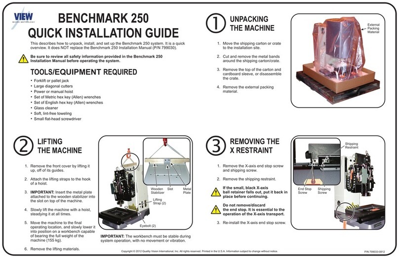
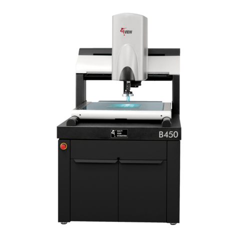
View Benchmark 250 User manual

VIEW Engineering, Inc.
VIEW Benchmark™250
Service Manual


VIEW Engineering, Inc.
VIEW Benchmark™ 250
Service Manual
Copyright © 2007 VIEW Engineering, Inc., a Quality Vision International
Company.
All rights reserved. Printed in the U.S.A.

Part No. 799015, Revision A, 06/07
Information in this document is subject to change without notice and
does not represent a commitment on the part of VIEW Engineering, Inc.
VIEW Benchmark, VIEW Engineering, and the VIEW Benchmark and
VIEW logos, are trademarks of VIEW Engineering, Inc. All other
trademarks mentioned in this manual are property of their respective
owners.
VIEW Benchmark equipment is made in the U.S.A.

Service Manual 799015, Revision A, 06/07 Page i
Table of Contents
Important System Labels vii
1 About This Manual 1
1.1 What This Chapter Contains 1
1.2 Who Should Read This Manual 1
1.3 Required Knowledge 2
1.4 What’s in This Manual? 2
1.5 Where to Read More 3
1.6 Where to Get Help 4
2 General Description 5
2.1 What This Chapter Contains 5
2.2 What is the Benchmark 250 System? 5
2.3 Benchmark 250 System Main Components 6
2.4 Coaxial Light, Programmable Ring Light, & Backlight 7
2.5 Dual Magnification Optical System 8
2.6 Computer & User-Interface Components 9
2.6.1 Mouse 9
2.6.2 Keyboard 9
2.6.3 Joystick 9
3 Safety Information 11
3.1 What This Chapter Contains 11
3.2 Emergency Stop Switch 11
3.3 System Status LEDs 12
3.4 System Power 13
3.5 System Lockout 14
3.6 Safety Guidelines 15

Page ii 799015, Revision A, 06/07 VIEW Benchmark 250
4 Installation 17
4.1 What This Chapter Contains 17
4.2 Choosing an Installation Site 18
4.3 Benchmark 250 System Layout 19
4.4 Receiving, Unpacking, &
Inspecting the Benchmark 250 System 20
4.5 Moving & Installing the System 21
4.6 Connecting the System 22
4.7 Powering Up the System &
Launching the Metrology Software 24
4.8 Operation Checks 25
4.9 Post Installation Checklist 26
4.10 Shutting Down the System 27
4.11 Installing the X, Y, & Z Shipping Restraints 28
4.12 Stage Fixture Mounting Holes 32
5 Principles of Operation & System Interconnections 33
5.1 What this Chapter Contains 33
5.2 Overview of Operation 34
5.3 Image Acquisition, Processing, & Display 35
5.4 Motion Control 36
5.4.1 X- & Y-Axis Motion 36
5.4.2 Z-Axis Motion 37
5.5 Illumination Sources 38
5.6 Optional Ronchi Grid Assembly 39
5.7 Optional AccuCentric Assembly 40
5.8 Zeroing the Stage 40
5.9 Benchmark 250 Schematic Diagram 40
6 Preventive Maintenance 43
6.1 What This Chapter Contains 43
6.2 Preventive Maintenance Schedule 44
6.3 Cleaning the User Components 45
6.3.1 Cleaning the Joystick 45
6.3.2 Cleaning the Mouse 45
6.3.3 Cleaning the Flat Panel Display 45
6.3.4 Cleaning the Keyboard 45
6.4 Cleaning the Stage, External Surfaces, & Stage Glass 46
6.4.1 Cleaning the Stage 46
6.4.2 Cleaning External Surfaces 46
6.4.3 Cleaning the Stage Glass 47
6.5 Cleaning & Lubricating the XY Stage Guide Rails 48
6.5.1 Cleaning & Lubricating the X-Axis Guide Rails 49
6.5.2 Cleaning & Lubricating the Y-Axis Guide Rails 51
6.6 Lubricating the X-Axis Drive Rod 53

Service Manual 799015, Revision A, 06/07 Page iii
6.7 Lubricating the Z-Axis Ball Screw 55
6.8 Cleaning the Magnification Lens 57
6.9 Cleaning the Optional LED Programmable
Ring Light (PRL) 59
6.10 Checking for Dirt in the Images of Both Cameras 60
6.11 Checking the System for Proper Function 60
7 Troubleshooting 61
7.1 What This Chapter Contains 61
7.2 Before You Begin 62
7.3 DSP Multi Axis PCBA Diagnostic LEDs & Test Points 63
7.3.1 DSP Multi Axis PCBA Diagnostic LEDs 63
7.3.2 Magnetic Limit Codes (DS7) 68
7.3.3 DSP Multi Axis PCBA Test Points 69
7.4 Dual Mag Optics PCBA Diagnostic LEDs & Test Points 71
7.4.1 Dual Mag Optics PCBA Diagnostic LEDs 71
7.4.2 Dual Mag Optics PCBA Test Points 74
7.5 Z Brake Control PCBA Diagnostic LEDs & Test Points 76
7.5.1 Z Brake Control PCBA Diagnostic LEDs 76
7.5.2 Z Brake Control PCBA Test Points 79
7.6 LED Driver PCBA Diagnostic LEDs & Test Points 81
7.6.1 LED Driver PCBA Diagnostic LEDs 81
7.6.2 LED Driver PCBA Test Points 83
7.7 Measuring the Resistance of the Drewire Terminations 85
7.8 Power Supply Diagnostic LEDs 86
7.9 Identifying Problems With the Benchmark 250 System 87
7.9.1 Start-Up Troubleshooting 87
7.9.2 Illumination Troubleshooting 88
7.9.3 Motion Troubleshooting 92
7.9.4 Video 101
7.10 Identifying Problems with the PC &
User-Interface Components 102
7.10.1 Start-Up & General Performance 102
7.10.2 Communications 103
7.10.3 Joystick 103
7.10.4 Troubleshooting the Joystick 104
7.10.5 Keyboard 108
7.10.6 Flat Panel Display 108
7.11 Troubleshooting the Power Supply 110
7.12 Troubleshooting the Safety Relay 112
7.13 Recovering from Unexpected Z-Axis Contact 113

Page iv 799015, Revision A, 06/07 VIEW Benchmark 250
8 Service Adjustments 115
8.1 What This Chapter Contains 115
8.2 Benchmark 250 Service Adjustments 116
8.3 Dual Magnification Optical System Adjustments 117
8.3.1 Component Location 117
8.3.2 Sequence of Optical Adjustments 118
8.3.3 Coaxial Illuminator &
Ronchi Shuttle Window Position Adjustment 119
8.3.4 Ronchi Shuttle Opto Switch Flag &
End Limits Adjustment 120
8.3.5 Ronchi Grid Rotation Adjustment 122
8.3.6 Camera Parfocal Adjustment 123
8.3.7 Camera Par-Center (Coaxial) Adjustment 127
8.3.8 Camera Rotation Adjustment 130
8.4 Lens Calibration 132
8.5 AccuCentric Assembly Alignment (If Equipped) 134
8.6 LED Programmable Ring Light (PRL)
Adjustments (If Equipped) 137
8.6.1 Centering the PRL 138
8.6.2 Adjusting the PRL Height 141
8.6.3 Setting Up the PRL Lights 144
8.6.4 Checking the PRL Light Setup
with the Light Test Part Program 148
8.7 Z Brake Adjustment 149
9 Parts Repair & Replacement 151
9.1 What This Chapter Contains 151
9.2 Repairing & Replacing Parts on Your System 152
9.3 Replacing the Magnification Lens 154
9.4 Replacing the High & Low Mag Cameras 155
9.5 Replacing the Programmable
Ring Light (PRL) (If Equipped) 157
9.6 Replacing the AccuCentric Assembly (If Equipped) 159
9.7 Replacing the Scale Reader Heads 161
9.7.1 Replacing the X-Axis Scale Reader Head 162
9.7.2 Replacing the Y-Axis Scale Reader Head 168
9.7.3 Replacing the Z-Axis Scale Reader Head 174
9.8 Replacing the Z-Axis Motor 178

Service Manual 799015, Revision A, 06/07 Page v
9.9 Replacing the PCBAs 182
9.9.1 Replacing the DSP Multi Axis PCBA 183
9.9.2 Replacing the Z Brake Control PCBA 185
9.9.3 Replacing the LED Driver PCBA 187
9.9.4 Replacing the Dual Mag Optics PCBA 189
9.9.5 Replacing the Universal
Multi-Sensor PCBA (If Equipped) 191
9.9.6 Replacing the Micro Theta
Control PCBA (If Equipped) 193
9.10 Replacing the Power Supply 195
9.11 Replacing the Exhaust Fan 198
A VMS System Certification & Verification 7.02 201
A.1 What This Appendix Contains 201
A.2 General Guidelines 201
A.3 Handling & Cleaning Grid Plates, Scales, & Lenses 202
A.4 Wringing Gage Blocks 202
A.5 System Certification 204
A.5.1 Certification Setup 205
A.5.2 XY Certification 208
A.5.3 Z Certification 212
A.6 System Verification 222
A.6.1 Verification Setup 223
A.6.2 XY Verification 226
A.6.3 Z Verification 230
B Accessing Parameters 241
B.1 What This Appendix Contains 241
B.2 Accessing Basic Parameters 242
B.3 Accessing Advanced Parameters 243
B.4 Loading Parameters 244
C Software Installation 245
C.1 What This Appendix Contains 245
C.2 VMS Software Installation 246
C.3 Elements Software Installation 251
Index 255

Page vi 799015, Revision A, 06/07 VIEW Benchmark 250
This page has been left intentionally blank.

Service Manual 7990xx, Revision A, 06/07 Page vii
Important System Labels
Label: Location: Definition:
Around the remote E-
Stop switch
(Yellow ring
around red
switch)
Emergency stop
Left and right sides of
the stage, on the
substage
Do not lift
Front surface of the
electronics tower
Z-axis slide, near Z-axis
ball screw
Pinch hazard
Rear panel of the
electronics tower
Right side of the
electronics tower, next to
the interconnection plate
Dangerous
voltage present;
disconnect
power before
servicing to
avoid electrical
shock
DANGER

Page viii 7990xx, Revision A, 06/07 View Benchmark 250
Right side of the
electronics tower, next to
the interconnection panel
Electrical
specifications
Lower-left corner of
Main System ID label
System meets
the requirements
of the European
Union (EU)
Front surface of the
electronics tower
System model
and serial
number
Right side of the
electronics tower, next to
the interconnection panel
Main system ID
Front surface of the
electronics tower
Z-axis slide, near Z-axis
ball screw
Exercise caution
near this area
Label: Location: Definition:

Service Manual 7990xx, Revision A, 06/07 Page ix
Right side of the laser (if
equipped)
International
laser symbol
Right side of the laser (if
equipped)
Indicates that
the laser meets
Class 2
requirements of
the IEC-825
European
standard
Right side of the laser (if
equipped)
Indicates that
the laser meets
Class II
requirements of
the CFR 21
standard
Right side of the laser (if
equipped)
Identifies the
laser emitting
aperture
Label: Location: Definition:

Page x 7990xx, Revision A, 06/07 View Benchmark 250
This page was left blank intentionally.

Service Manual 799015, Revision A, 06/07 Page1
Chapter
About This Manual
1.1 What This Chapter Contains
This chapter explains:
• Who Should Read This Manual
• Required Knowledge
• What’s in This Manual?
• Where to Read More
• Where to Get Help
1.2 Who Should Read This Manual
Read this manual if you will perform any of the following tasks on the Benchmark
250 system:
• Installation
• Preventive maintenance
• Troubleshooting
• Service adjustments
• Parts replacement
For information on programming and configuring, refer to the VMS Fast Start
Guide (P/N 790438) and VMS Reference Guide (P/N 790411).
1

Chapter 1 About This Manual
Page 2 799015, Revision A, 06/07 VIEW Benchmark 250
1.3 Required Knowledge
To use this manual, you should be familiar with:
• How to maintain and service inspection or industrial automation equipment
• How to use, troubleshoot, and repair a PC
• Basic electrical and mechanical terminology and inspection equipment
terminology
1.4 What’s in This Manual?
Note: We recommend that the procedures in this manual be performed by trained
and authorized personnel.
Chapter Title Contents
2 General Description Defines what the Benchmark 250
system is and familiarizes you with
the system’s basic hardware
components
3 Safety Information Describes the remote Emergency
Stop switch and covers other safety
issues
4 Installation Describes how to:
• choose an installation site
• unpack, move and install the
Benchmark 250 system
• start up the system, perform
verification, and shut down the
system
5 Principles of Operation &
System Interconnections
Describes subsystems and the
interconnections within the
Benchmark 250 system
6 Preventive Maintenance Lists actions you should take to
keep the Benchmark 250 system in
good operating order
7 Troubleshooting Helps you identify the cause of
possible problems with the
Benchmark 250 system, the CPU,
and the user components

About This Manual Chapter 1
Service Manual 799015, Revision A, 06/07 Page3
1.5 Where to Read More
For information about using the Benchmark 250 system, refer to the software
manual(s), software release notes, and OEM manuals that shipped with your
system.
8 Service Adjustments Describes how to calibrate and
align the Benchmark 250 system
9 Parts Repair &
Replacement
Describes how to replace imaging,
transport, and electrical parts
A VMS System Certification
& Verification 7.02
Describes how to certify and verify
the Benchmark 250 system
B Accessing Parameters Describes how to access VMS and
Basic-X related parameters
C Software Installation Describes how to install the VMS
software, the Basic-X software,
and the Elements software
Chapter Title Contents

Chapter 1 About This Manual
Page 4 799015, Revision A, 06/07 VIEW Benchmark 250
1.6 Where to Get Help
If you are faced with a situation you cannot resolve using this manual, contact the
Customer Support HelpDesk, at:
Please be prepared with the following information when contacting us:
• Model and serial number of your system
• Nature of problem
• Steps you have taken
• Your phone and fax numbers
• Case number if you are calling about an issue you have already reported
1650 N. Voyager Avenue
Simi Valley, CA 93063, USA
Phone: 805-578-5000
Toll free: 877-SOS-VIEW
(877-767-8439)
Fax: 805-578-5249
E-mail: [email protected]
Website: www.vieweng.com

Service Manual 799015, Revision A, 06/07 Page5
Chapter
General Description
2.1 What This Chapter Contains
This chapter covers:
• What is the Benchmark 250 System?
• Benchmark 250 System Main Components
• Coaxial Light, Programmable Ring Light, & Backlight
• Dual Magnification Optical System
• Computer & User-Interface Components
2.2 What is the Benchmark 250 System?
The Benchmark 250 system is a non-contact, three-dimensional measurement
system with a full range of vision-based measurement tools and software. It has
300 mm x 150 mm x 150 mm (12" x 6" x 6") XYZ travel—200 mm (8") Z travel is
optional.
The system has precision dual magnification optics, coaxial and backlight
illumination, and patented autofocus circuitry for high-accuracy Z-axis
measurements over a variety of surface textures, finishes, and colors. The patented
LED Programmable Ring Light (PRL) is optional.
No upgrades are necessary to achieve full automatic inspection.
Note: See the VIEW Benchmark 250 Technical Data Sheet (part number 799002)
for more technical information.
2

Chapter 2 General Description
Page 6 799015, Revision A, 06/07 VIEW Benchmark 250
2.3 Benchmark 250 System Main Components
The Benchmark 250 is a benchtop machine. Parts are measured by mounting them
on the measuring stage, which moves in both the X and Y directions. An optional
workstation is available for the system computer, flat panel display, 3-axis
joystick, keyboard, mouse, and remote E-Stop switch.
Figure 2-1 Benchmark 250 System Main Components
System Computer (PC)
Measuring
Stage
3-Axis Joystick Keyboard
Mouse
Remote E-
Stop Switch
Flat Panel Display
Front Cover Electronics Tower
Other manuals for Benchmark 250
2
Table of contents
Other View Laboratory Equipment manuals