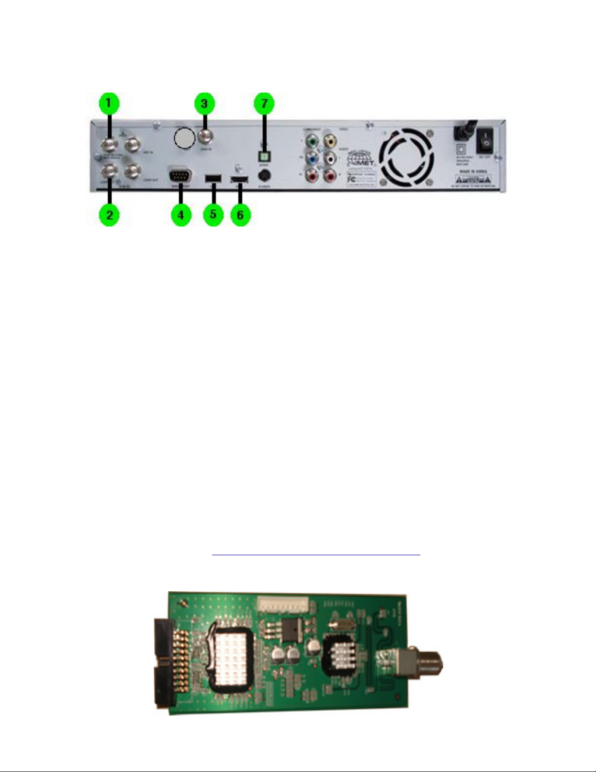
ViewSat VS9000HD User manual

VIEWSAT 9000HD User Troubleshooting Guide & Manual.
•is manual was constructed for the FATDOC growing population of new VS9000HD users.
•Use the manual for a quick reference guide when things go wrong with your unit. Answers are listed below.
•Please read each section of this manual and familiarize yourself with key features for troubleshooting.
is manual was created for all VS9000HD owners of the world..... enjoy.
A paper life raft
Table of Content:
•1............. HOW TO CONNECT YOUR RECEIVER
•2............. 8PSK CARD
•3............. SET-UP SYSTEM
•4............. MENU STRUCTURE
•5............. INSTALLING FIRMWARE / BIN FILES
•6............. SPDIF AUDIO
•7............. RECORD/PLAYBACK
•8............. CABLES
•9............. HOW TO RECOVER FROM BOOT-LOOP
•10........... COPY FILES TO FLASH DRIVES
•11........... SAVING CHANNELS/SATELLITE INFORMATION
•12........... SATELLITE DISHES AND LNBs
•13........... SWITCHES
•14........... ANTENNA SET-UP
•15........... CHANNEL SCAN
• 16........... TROUBLESHOOTING / QUICK TIPS
SAFTY PRECAUTIONS:
Do not block the receiver ventilation holes. Ensure that free airflow is maintained around the receiver. Never
set the receiver on soft furnishings or carpets. Do not use or store the receiver where it is exposed to direct
sunlight, or near heater. Never stack other electronic equipment on top of the receiver. Place the receiver at
least 30mm from the wall.
CAUTION:
Changers or modifications not expressly approved by manufacture responsible for compliance could void the
users authority to operate the equipment. Main Software still resides in BETA.
Document page.1
VIEWSAT 9000HD User Troubleshooting Guide & Manual. April /2008

(1) HOW TO CONNECT YOUR RECEIVER: REAR PANEL:
•1. Satellite IN Connect RG6 Cable.
•2. Loop-Out
•3. UHF Remote Antenna Module / Replace with 8PSK Module
•4. Serial Port
•5. USB Port
•6. HDMI Output
•7. SPDIF Digital Output
NOTE: When 8PSK Card is used RG6 Cable connects between 3 and 2 this allows HD with US
Providers.
NOTE: With Revision 1 VS9000HD unit here is only one port showing as I have shown , Revision 2
has two ports for the UHF Module insert.
(2) 8PSK CARD INSTALLATION AND CONNECTION:
•1. Remove the cover and face the front towards you.
•2. is is Important GROUND your self or DISCHARGE any static electricity by touching METAL
before you continue.
•3. e 8PSK Module come with two cables one black one white and they will only connect to their
connectors, you can not cross them.
•4. Remove the UHF Remote Antenna Module and replace it with the 8PSK Module.
•5. Connect the black cable to the connector at the bottom side of the 8PSK to connector of MLB
(main logic board) connect the white cable 8PSK to the top/left connector of the MLB.
•Replace the cover.
Complete Installation guide go to: http://www.youtube.com/watch?v=0QB58hjyjXA
VS9000HD 8PSK UHF Adapter Module:
Document page.2
VIEWSAT 9000HD User Troubleshooting Guide & Manual. April /2008

(3) SET UP SYSTEM:
•1. From your Satellite RG6 cable connect it to Dish In.
•2. Loop-OUT is connect to the 8PSK Card Module IN.
•3. 8PSK IN is connected to Loop-OUT.
•4. Serial Port is connected to your LapTop for File Transfer as needed.
•5. USB Port is used STB Software upgrades and for Recording to a External Hard Drive. Front/Rear.
•6. HDMI is used to connect to Receiver or HDTV or other.
•7. SPDIF is used to connect Optical Digital Audio to a Receiver or Other Device with same interface.
NOTE: Make sure all connections are in good order and connected to there right IN/OUT-PUTS.
Problems are found when this is not achieved or components are not in good order.
NOTE: Turn VS9000HD Unit ON and load software.
(4) MENU STRUCTURE: SEE VS9000HD MANUAL FOR ALL CHANGERS:
(5) LOADING SOFTWARE:
•1. loading the (BF) Bin File via USB Flash Drive, insert it into the front panel USB connector behind
the front panel cover by pushing the cover in to unlock.
•2. Change you TV INPUT to Satellite INPUT and press OK.
•3. On the Remote Control press Menu and this will bring up the Main Menu of the VS9000HD
receiver.
•4. Scroll down to System Information / Receiver Upgrade and select USB at the bottom of the Menu.
•5. Firmware upgrade and Bin Files are uploaded here using USB flash drive. Press OK
•6. Select the firmware / Bin File upgrade file from the USB Drive and press OK.
•7. When file transfer is completed, the receiver will be automatically rebooted.
NOTE: If the transfer stops or gets distorted just turn the receiver offin the back and start again.
After you restart and the display just shows BOOT refer to BOOT-LOOP section. In this section you
can recover from Boot-Loop. Boot-Loop is common when a wrong or corrupted file is loaded.
Set Up Receiver User Settings:
Settings that need to be turned on:
•1. Time Settings: You can change the time Zone of your receiver and also switch on/offthe timer
function in this menu.
•2. Parental Control: is function prevents children or unauthorized persons from watching
programs. Also you can change PIN (Personal Identification Number) code in this menu.
•3. System Settings: Make sure the EXT Tuner is turned ON if Installed.
•4. System Settings / Options: Sort by SID is ON, Auto TP is ON, Auto Roll is ALL, Full Channel
Name is ON, BEV Channel Mapping is ON, Audio Select Method is Method 2, USB Port is Front.
•5. EPG Settings: Reservation Notice is ON, EPG TP set to E:12224 N: 12676
•6. Factory Default: Use this when you install a new Bin File or you are having problems with any
part of the software. is operation will reset the receiver back to Factory Default so you can start
fresh again. Factory Default will not load new FIRMWARE.
(6) SPDIF AUDIO:
•1. SPDIF Digital Audio require a special optical cable to connect between the VS9000HD receiver
and a Digital Audio Receiver or HDTV. SPDIF data is transmitted as a stream of 32-bit data words. A
data frame consists of 384 words in total, with 192 data words transmitted for the A stereo channel,
and 192 data words transmitted for the B stereo channel. Belkin makes High Quality SPDIF Optical
cables.
Document page.3
VIEWSAT 9000HD User Troubleshooting Guide & Manual. April /2008

(7) HOW TO RECORD AND PLAYBACK:
•1. If recording time is less than 30 seconds, the event will not be saved.
•2. Make sure that Reservations is turned on in the EPG Settings.
•3. Install a External Hard Drive Formatted by the VS9000HD receiver or the Drive is in FAT 32
format. Use the REAR USB connector to record.
•4. In the Guide you can select Record now or Future Events by selecting a time to record and then
press F1.
•5. F1 will give you a selection RECORD / VIEW choose Record.
•6. Once the selection starts recording a RED (R) will display but will turn offin about minute, you are
still recording if there is a RED indicator light on the VS9000HD Display.
NOTE: Format External Drive via VS9000HD receiver. With the External Drive connected to USB port
select Menu / Main Menu / Media / USB Storage / OK / Yes.
Playback:
•1. Select Main Menu / Menu / Media / DVR and a list will show with your recordings as
VSHD_DATA / Press OK. In side this folder your recordings will be listed.
NOTE: is software still resides in BETA and problems do accrue so keep a new copy of the
FIRMWARE / Bin File handy, when problems can not be resolved, it’s best to select Factory Default
and load a new Bin File. is will save time and frustrations and get you up and running a lot quicker.
(8) CABLES:
• 1. RG-6, Copper Coated Steal Coax Cable.
Standard Shield with Waterproof Layer, FR-PE Jacket, For Direct Burial.
60% Aluminum Braid Over Foil Provides 100% Shield Coverage.
18AWG Solid .040” Bare Copper-Clad Steel Conductor.
Gas Injected Foam Polyethylene Insulation.
Ideal for RF Applications Like Outdoor TV Antennas and Cable Television.
Aluminum-Mylar Shield and a 60% inner Copper Shield.
CM/CL2 Rated PVC Jacket.
Sweep Tested to 2.2GHz.
Sequential Foot Marking.
UL Listed.
•2. Snap-N-Seal Connectors are the most effective.
•connectors used with RG6.
•3. SPDIF. Optical. Belkin make the best SPDIF Audio Cables in the US.
•4. RCA Cables. Belkin Make the best RCA Cables in the US.
•5. HDMI. (High-Definition Multimedia Interface) is the first and only industry-supported,
uncompressed, all-digital audio/video interface. By delivering crystal-clear, all-digital audio and video
via a single cable, HDMI dramatically simplifies cabling and helps provide consumers with the
highest-quality home theater experience. HDMI provides an interface between any audio/video
source, such as a set-top box, DVD player, or A.V. receiver and an audio and / or video monitor, such
as a digital television (DTV), over a single cable.
• 6. 8PSK cable should be RG6 about 7” in length connected between 8PSK Tuner and Loop OUT on
the VS9000HD Receiver.
NOTE: All cables are only as good as they are kept.
Document page.4
VIEWSAT 9000HD User Troubleshooting Guide & Manual. April /2008

(9) HOW TO RECOVER FROM BOOT-LOOP:
• 1. Make sure that you are in fact suffering from BOOT-LOOP. (BOOT) will be steady on your
VS9000HD display and not move to the time setting.
• 2. Make sure that you have a Laptop and a NULL cable to connect between the Laptop and the
receiver. REMOVE the receiver from all connections.
• 3. Find a solid copy of LOADER 2 and (VS9000HD Boot fix_v2.pgm) to recover your VS9000HD
receiver.
• 4. Connect the NULL cable to the receiver and Laptop and don’t power the receiver on at this time.
• 5. Launch BOOT-LOADER 2 from your laptop and open the file (VS9000HD Boot fix_v2.pgm)
make sure that you select (PC-STB) and click (OK).
• 6. Once the VS9000HD Boot fix_v2.pgm) STARTS: turn on the receiver this will take about 6
seconds to get under way. Now because the fix file is about 33 mb it will take some time to complete.
My first try it took about 45 minutes but it works. You will see the indicator bar get out of sync and
do strange stuff, don’t worry about what you see just let it finish.
• 7. When completed you will see completed on the laptop screen so select OK and turn the
VS9000HD receiver OFF.
• 8. Locate a good copy of the (VS9000HD FIRMWARE) and load it into the laptop the same way you
did with the (VS9000HD Boot fix_v2.pgm) file. Start the file and turn the receiver ON. and let it
complete. e receiver will now reboot and you will feel joy. Disconnect every thing and reconnect
the receiver back to the Satellite position.
•9. You are now back to normal and at this point you can load the current bin file via USB
Tools you will need.
• 1. A fast Laptop with a NULL cable.
• 2. e Application LOADER 2.
• 3. e file VS9000HD Boot fix_v2.pgm).
• 4. e file VS9000HD Factory FIRMWARE v108.
• 5. e copy of the latest bin file, you can load this via USB.
NOTE: I have discovered a faster way to recover from Boot-Loop and that is you can just load the
FIRMWARE File v108 Via LOADER 2 and this will saves time. After the Firmware is loaded you can
now load a new Bin File.
(10) COPY FILES TO FLASH DRIVES:
• 1. Select Menu / System Information / Receiver Upgrade. In this Menu you can copy your Channel /
Satellite List to a USB Flash Drive to save them.
(11) SAVING CHANNELS / SATELLITE INFORMATION:
•1. After you saved your Channel / Satellite List to your USB now you can Upload them back to the
VS9000HD Receiver. After you have installed a new Bin File go to Menu / System Information /
Receiver Upgrade / USB and press OK. is will take you to a directory on your USB Flash Drive
where your information is saved. To upload the Data, select it and press OK. Your saved Data has
now been uploaded.
USB Flash Drives: Of all the Flash Drives I have tested I have found Sandisk / Memorex the most
reliable of all Drives.
NOTE: is is a good practice to put back all Favorite Channel / Satellite List after a new Bin File has
been upload.
Document page.5
VIEWSAT 9000HD User Troubleshooting Guide & Manual. April /2008

(12) SATELLITE DISHES AND LNBs:
ere are many types of Satellites Dishes but not that many for HD Receivers. As far as LNBs I have found
most work with HD Receivers.
A satellite dish is a type of parabolic antenna designed with the specific purpose of transmitting signals to
and from a destination, whether it be a satellite or an aerial eg: WIFI ANTENNA. A satellite dish is a
particular type of microwave antenna. Satellite dishes come in varying sizes and designs, and are most
commonly used to receive satellite television. Many of the offset type of satellite dishes are sections of a
larger parabolic dish.
e parabolic shape of a dish reflects the signal to the dish’s focal point. Mounted on brackets at the dish's
focal point is a device called a feedhorn. is feedhorn is essentially the front-end of a waveguide that
gathers the signals at or near the focal point and 'conducts' them to a low-noise block downconverter or
LNB. e LNB converts the signals from electromagnetic or radio waves to electrical signals and shifts the
signals from the downlinked C-band and/or Ku-band to the L-band range. Direct broadcast satellite dishes
use an LNBF, which integrates the feedhorn with the LNB. (A new form of omnidirectional satellite antenna,
which does not use a directed parabolic dish and can be used on a mobile platform such as a vehicle was
announced by the University of Waterloo).
Modern dishes intended for home television use are generally 43 cm (18 in) to 80 cm (31 in) in diameter, and
are fixed in one position, for Ku-band reception from one orbital position. Prior to the existence of direct
broadcast satellite services, home users would generally have a Motorized C-band satellite dish of up to 3
meters in diameter for reception of channels from different satellites. Overly small dishes can still cause
problems, however, including rain fade and interference from adjacent satellites.
Motorized satellite dishes are still popular with enthusiasts. ere are three competing standards, which
often are all supported by a set-top box, DiSEqC, USALS, and 36v positioners. ey can only supply one
receiver.
ree Different Satellites that are used with HD receivers.
from the left: Dish 1000.2 3 LNBs Center: Dish Plus 30” 2 LNBs Right: Dish 500 Pro 2 LNBs
NOTE: Direct TV and other HD Satellites Providers not shown.
Problem with Satellites are with Connections, Cables, LNBs and dialing the Dish to target.
Document page.6
VIEWSAT 9000HD User Troubleshooting Guide & Manual. April /2008

(13) SWITCHES:
from left to right:
DISHPRO DPP-44 Switch allows you to pick up to 4 satellite locations and distribute them to up to 4 DISH
Network Receivers. Power inserter included.
• In addition when used with the DP Separator (purchased separately) enables you to run 1 cable into the
home and feed dual tuner DISHPro Receivers (921, 721, 522 and 322) making installations a snap
• Built in DISH Pro Adaptor which will allow this switch to be used with any DISH Network receiver
including older legacy equipment.
DISHPRO DP-34 Switch Works with Dish 300 and Dish 500 satellite systems. Can be used to cascade
additional DP34 multi switches for more receiver outputs. Can only be used with DishPro LNBFs.
• Switch has 3 trunk outputs for cascading to an additional DP34 switch for more outputs
• Can be used indoors or outdoors
• Does not require power insertion / power supply
• Four outputs for connection to up to four DISH Network satellite receivers
• ree satellite inputs for use with up to three orbital locations
•e first switch in the new DishPro Technology series of LNBFs and switches
DISHPRO DP-21 Switch Two inputs for use with up to three orbital locations - 1 tuner output - Can be
used with a DishPro Twin (or DishPro Quad LNBF) and a DishPro Single LNBF to provide three orbital
locations to one tuner.
• Can be used indoors and outdoors
•Does not require power insertion
Zinwell Multi-switch Model SAM4402-3A is designed to distribute 2 Polarizations (usually RHCP and
LHCP or V/H) from 2 satellites to up to 4 IRDs. Polarization selection is by 13V/18V LNB voltage switching.
• is unit is powered by the receivers
• Works great with the Channel Master Gain Master dish
• Do not put any Termintators on any input/output ports
• Use this device to hook up four receivers to a two satellite dish (with 4 coax connections) or to two dual-
LNB dishes where each dish is pointed at a separate satellite
•Provides signals from two satellites to up to four receivers
NOTE: Problems with Switchers are Connectors, wrong Connection, Power Inserters, Voltage, they
just go bad.
Document page.7
VIEWSAT 9000HD User Troubleshooting Guide & Manual. April /2008

(14) ANTENNA SET-UP.
SATELLITE SET-UP FOR VS9000HD RECEIVER:
Satellites 119 / 110 / 91 / 82 ON THREE RECEIVERS
Using DPP44 switch with 1000.2 & Super dish no 8PSK Card.
Do a Factory Default first and upload new Bin File to Receiver.
Go To / Menu/Antenna Set-Up.
Select Satellite to use.
EchoStar 7 119.0W
LNB* power = on
LNB* type = ocs-dp (Set LNB Type Here)
LNB* freq = 11250
22KHz = off
TP* Freq = 12239
Diseqc* 1.0 = Port 1
Motor = Off
Legacy SW = None
"Exit" & save.
EchoStar 8,10 110.0W
LNB* power = on
LNB* type = ocs-dp (Set LNB Type Here)
LNB* freq = 11250
22KHz = off
TP* Freq = 12224
Diseqc* 1.0 = Port 2
Motor = Off
Legacy SW = None
"Exit" & save.
Nimiq 1,3 91.0W
LNB* power = on
LNB* type = ocs-dp (Set LNB Type Here)
LNB* freq = 11250
22KHz = off
TP* Freq = 12224
Diseqc* 1.0 = Port 3
Motor = Off
Legacy SW = None
"Exit" & save.
Nimiq 2 82.0W
LNB* power = on
LNB* type = ocs-dp (Set LNB Type Here)
LNB* freq = 11250
22KHz = off
TP* Freq = 12224
Diseqc* 1.0 = Port 4
Motor = Off
Legacy SW = None
"Exit" & save.
Document page.8
VIEWSAT 9000HD User Troubleshooting Guide & Manual. April /2008

ANTENNA SET-UP CONTINUED.
SATELLITE SET-UP FOR VS9000HD RECEIVER:
Satellites 82 / 91 / 129 / 119 / 110 ON ONE / THREE RECEIVER
Using Dish 1000.2 & Dish 500 PRO 2LNBs / DN 21 Switch with 8PSK Card
Do a Factory Default first and upload new Bin File to Receiver.
Go To / Menu / Antenna Set-Up
Select Satellite to use.
EchoStar 7 119.0W
LNB* power = on
LNB* type = ocs-dp (Set LNB Type Here)
LNB* freq = 11250
22KHz = off
TP* Freq = 12239
Diseqc* 1.0 = Port 1
Motor = Off
Legacy SW = SW21-DISH 1
"Exit" & save.
EchoStar 8,10 110.0W
LNB* power = on
LNB* type = ocs-dp (Set LNB Type Here)
LNB* freq = 11250
22KHz = off
TP* Freq = 12224
Diseqc* 1.0 = Port 2
Motor = Off
Legacy SW = SW21-DISH 1
"Exit" & save.
EchoStar 5 129.0W
LNB* power = on
LNB* type = ocs-dp (Set LNB Type Here)
LNB* freq = 11250
22KHz = off
TP* Freq = 12224/12239
Diseqc* 1.0 = Port 3
Motor = Off
Legacy SW = SW21-DISH 1
"Exit" & save.
Nimiq 1,3 91.0W
LNB* power = on
LNB* type = ocs-dp (Set LNB Type Here)
LNB* freq = 11250
22KHz = off
TP* Freq = 12224
Diseqc* 1.0 = Port 4
Motor = Off
Legacy SW = SW21-DISH 2
"Exit" & save.
Document page.9
VIEWSAT 9000HD User Troubleshooting Guide & Manual. April /2008

ANTENNA SET-UP CONTINUED.
Nimiq 2 82.0W
LNB* power = on
LNB* type = ocs-dp (Set LNB Type Here)
LNB* freq = 11250
22KHz = off
TP* Freq = 12224
Diseqc* 1.0 = Port 4
Motor = Off
Legacy SW = SW21-DISH 1
"Exit" & save.
5 Satellites on One Receiver:
• 1. Now you have 5 LNBs on one receiver and I will show you just how this all works. Dish 1000.2 has
a DPP 44 switch built in so you can have 3 RECEIVERS or ONE For now I will set-up just ONE
Receiver. I will show you all so 3 Receivers.
• 2. Add RG6 cable to the center port of Dish 1000.2 port. e center port is 119. e other end go’s
into the INPUT DP-21 Switch-1
• 3. Dish 500 Pro 2 LNBs/ Take the RG6 from LNB82 and connect to the INPUT PORT of the 1000.2
• 4. Dish 500 Pro 2 LNBs/ RG6 cable from LNB91 and connect it into INPUT 2 of the DP-21 Switch.
• 5. Now you have 2 RG6 Cables connected to the DP-21 Switch. One from the 1000.2 and one from
the Dish 500 Pro.
• 6. RG6 cable into the OUTPUT of the DP-21 Switch to your RECEIVER.
•7. Now for 3 RECEIVERS you will need RG6 cables on 1000.2 PORTS 110/129 to each RECEIVER.
Document page.10
VIEWSAT 9000HD User Troubleshooting Guide & Manual. April /2008

ANTENNA SET-UP CONTINUED.
SATELLITE SET-UP FOR VS9000HD RECEIVER:
Satellites 118.8 / 119 / 110 ON ONE / THREE RECEIVER
Using DPP44 Switch / Dish 1000 Plus with 8PSK Card
Do a Factory Default first and upload new Bin File to Receiver.
Go To / Menu / Antenna Set-Up
Select Satellite to use.
EchoStar 7 119.0W
LNB* power = on
LNB* type = ocs-dp (Set LNB Type Here)
LNB* freq = 11250
22KHz = off
TP* Freq = 12239
Diseqc* 1.0 = Port 1
Motor = Off
Legacy SW = None
"Exit" & save.
EchoStar 8,10 110.0W
LNB* power = on
LNB* type = ocs-dp (Set LNB Type Here)
LNB* freq = 11250
22KHz = off
TP* Freq = 12224
Diseqc* 1.0 = Port 2
Motor = Off
Legacy SW = None
"Exit" & save.
Anik F3 at 118.8°W
LNB* power = on
LNB* type = Universal (Set LNB Type Here)
LNB* freq = 975 / 10750
22KHz = off
TP* Freq = 11715
Diseqc* 1.0 = Port 3
Motor = Off
Legacy SW = None
"Exit" & save.
Additional Information on Anik (F3) 118.8 W.
Go To / Menu / Antenna Set-Up
For this Satellite Select Echo 9-121W
LNB Type: Standard
LNB Freq: 10750
TP Freq: 11715
Turn OFF LNB Power to all other LNBs that are currently setup. Now you will not see TP freq: 11715. In
order for the Receiver to find all Available TP Freq for 118.8W, Make Certain your Auto TP is set to ON.
Document page.11
VIEWSAT 9000HD User Troubleshooting Guide & Manual. April /2008

ANTENNA SET-UP CONTINUED.
en do this:
Preparing the TP Frequencies for Echo 9-121W:
Go to Menu -> Installation -> Channel Scan
Select EchoStar 9
Scroll down to Edit TP -> OK
Now scroll thru the window and delete all the TP Freqs by pressing the [F3] Delete TP button.
en, while in this window: Press F1 to Add User TP Enter: TP Freq: 11715...S/R: 20000...Pol: V...FEC: 7/8
Exit and then Save.
Now go to Auto Scan:
Auto Scanning all available TP Freqs and Channels from 118.8w (121W):
Echo 9 should be selected, Scan Search All, Scroll down one and turn Network search to OFF (right arrow).
Highlight Start Scan and Hit Ok. You should now get over 123 channels if your dish is 24" or larger.
Please Note: No Sat ID lock will be displayed at the top right hand corner of the screen. e coders have not
included this function yet. While TP Freq 11715 is chosen you should have a Q signal of 20% or higher. is
signal strength is strong enough to scan TPs and Channels and no pixelation should occur while viewing.
e larger the dish of course the higher the Q signal value.
Update:
For those using the Special LNB for 119/118.8 from Digiwave, try these settings below (From the Digiwave
Site itself) Digiwave LNB Setup Instructions Using a 30-inch or larger dish, aim with the following settings:
For DGL-1189S you should setup as below will work better: Satellite Name: 118.8°W (Anik F3) or 119°W
(Echo7)
* LNB Power: ON
* LNB Type: Universal
* LNB Frequency: 9750Mhz/10750 MHz
Finally, do an AUTO SCAN or a BLIND SCAN
For DGL-1189D and DGL-1189Q you should setup as: Satellite Name: 118°W (Anik F3) or 119°W (Echo7)
* LNB Power: ON
* LNB Type: Universal
* LNB Frequency: 9750Mhz/10600 MHz
Finally, do the Auto Scan procedure above.
3 Types of KU LNBs used for Satellite 118.8. Dish 30” Plus with KU Band Optical LNB
Document page.12
VIEWSAT 9000HD User Troubleshooting Guide & Manual. April /2008

ANTENNA SET-UP CONTINUED.
SATELLITE SET-UP FOR VS9000HD RECEIVER:
Satellites 82 / 91 / ON ONE / TWO RECEIVER
Using Dish 500 PRO 2LNBs with 8PSK Card.
Do a Factory Default first and upload new Bin File to Receiver.
Duel Output. So no switch is needed.
If more then 2 satellite port numbers will need to be changed.
Go To / Menu / Antenna Set-Up
Select Satellite to use.
Nimiq 1,3 91.0W
LNB* power = on
LNB* type = ocs-dp (Set LNB Type Here)
LNB* freq = 11250
22KHz = off
TP* Freq = 12224
Diseqc* 1.0 = Port 1
Motor = Off
Legacy SW = None
"Exit" & save.
Nimiq 2 82.0W
LNB* power = on
LNB* type = ocs-dp ((Set LNB Type Here)
LNB* freq = 11250
22KHz = off
TP* Freq = 12224
Diseqc* 1.0 = Port 2
Motor = Off
Legacy SW = None
"Exit" & save.
NOTE: It is a good practice to check your settings regularly to maintain good viewing.
Resolving Satellite and LNB problems:
Poor Reception Possible causes:
• 1. A signal isn’t getting from dish to receiver. is may be a cabling problem.
• 2. Your dish isn’t picking up a signal.
• 3. Your receiver is getting a signal but isn’t processing the signal correctly.
• 4. A severe storm has temporarily interfered with the signal.
ANTENNA ALIGNMENT:
e station's dish antenna require three different adjustments for proper alignment:
AZIMUTH, ELEVATION, POLARIZATION:
AZIMUTH: Compass direction the antenna is pointed towards, relative to a magnetic north. is is also
referred to as the left or right movement (position) of the satellite antenna. When calculating azimuth, you
must also take in to account your DECLINATION . is is the difference between magnetic north and true
north. e declination must be added or subtracted from your azimuth for proper antenna pointing.
Azimuth is expressed in degrees clockwise from true north.
Document page.13
VIEWSAT 9000HD User Troubleshooting Guide & Manual. April /2008

ANTENNA SET-UP CONTINUED.
ELEVATION: Angle between the Earth and the satellite above the horizon. is is also referred to as the up
or down movement (position) of the satellite antenna.
POLARIZATION: Correction between where the antenna is relative to the curvature of the Earth and the
satellite's signal beam. e satellite signal is either Horizontal or Vertical polarized, but due to the longitude
of the antenna location, the antenna's feed horn must be rotated to correctly match the beam's polarization.
If you choose to perform the antenna alignment yourself, you must align the azimuth and elevation settings
independently. Once the antenna is pointed at the satellite, minor adjustments should be made to “peak” the
antenna, which will maximize your signal strength. It is recommends using a spectrum analyzer to align the
antenna for least interference and best reception. When adjusting polarization, it is best to perform the
alignment to MINIMIZE the interfering signals instead of MAXIMIZING the carrier's signal strength .
If you are peaking the dish with a spectrum analyzer, you will be able to see if your antenna is picking up any
interference around the carrier. e adjacent transponders on the desired satellite will be polarized opposite
to the target signal transponder.
TRANSPONDER INTERFERENCE: is problem manifests itself in random audio dropouts and a
momentary fault indication on the front panel of the FTA receiver. You may also see the Eb reading dip when
the dropout occurs. If a dish is not properly polarized, the receiver may “see” some unwanted signals from
either adjacent transponder on the satellite. is problem can be fixed by correct adjustment of dish
polarization.
SOLUTIONS:
Check everything that could be preventing the signal transmission.
• 1. Make sure your dish has not moved.
•2. Make sure nothing is blocking the dish.
•3. Make sure the cables that run from dish to receiver are securely connected, and connections
exposed outside your home are sealed with silicone at the connectors.
• 4. If you had severe weather, inspect your dish for debris or misalignment.
Inspect or realign your dish when you can easily and safely do so. Dishes often get out of alignment or settle
form bad weather.
Disconnect and reconnect all cable ends between the dish and the receiver. Start with the SAT–IN
connection at the back of your receiver and work your way to the dish. Take out each cable and inspect it.
Check the center wire in the cable. If the wire is bent, straighten it. Reconnect the cable. Be sure it’s securely
connected. If you see corrosion in the cable connection, it is best to replace the connectors and seal with
silicone gel to avoid problems in the future. Long cable lines (more than 100 feet) may need additional power
to improve signals.
Test the signal strength using your remote and on–screen menu. Your owner’s manual explains how to run a
signal test. In clear weather, the strength should be over 70 on most transponders. If it’s not, your problem is
probably with your cable connections or dish pointing. For High–Definition receivers 60 or above is normal.
You may see signal strength of zero on transponders 0 is is normal in many areas. Find a system manual to
shows how to run cables and point your dish.
Reset your receiver by turning it offand unplugging it. Wait 15 seconds, then plug it back in and turn
it on.
NOTE: Make sure the Cables, Connectors and Satellite Dishes are maintained at all times.
Document page.14
VIEWSAT 9000HD User Troubleshooting Guide & Manual. April /2008

ANTENNA SET-UP CONTINUED.
e Satellite Site Survey:
A Site Survey is a fancy term used to make you think it’s something highly technical when in fact it’s not. All
you do is grab a magnetic compass or GPS and see where you can put a satellite receiving dish on your
property and receive signals. Not all locations are capable of receiving satellite signals because of natural or
man-made obstructions. e signal from satellites is relatively weak and directional so we must have an un-
obstructed view of the satellite in order to receive a satisfactory signal. Also keep in mind seasonal changes.
We don’t want to install our dish in a location that will be blocked when the new leaves emerge in spring. If a
particular location in your yard is not suitable then moving the location as little as a few feet can make a
tremendous difference. If you have a clear southeastern to southwestern sky then you are in luck.
First, let’s find out where your chosen satellites are in relation to your location. By far the easiest way is using
a program that automatically compensates for magnetic deviation and takes into account which satellites you
want to receive. ere are many programs available to assist you in locating satellites. Satellite programs
include SatFinder (http://www.arachnoid.com/satfinder) and Zip Code32 and Dish Point which can be found
in the tools and hardware section of this site. e results from Zip Code32 and Dish Point are already
adjusted for magnetic declination and skew however; both programs rely on U.S. zip codes to calculate the
parameters and are written for Dish Net Satellites only. I have selected two of the most popular North
American satellites for our exercise. ey are at longitude 110 (ECHO 6/8 or Echo 10) and 119 (ECHO 7),
both satellites require circular polarized LNBFs.
Run the satellite program of your choice. For this exercise we will use Satfinder since it is pretty much
universal and can be used anywhere. Load and run the program. Let’s say our zip code is 20301, (Pentagon,
Washington, DC). Locate the 110 satellite in the list and you see azimuth of 237(m) degrees and elevation of
33.5 degrees with a skew of 34 degrees. Now find the 119 satellite and your azimuth is 246.5(m) and
elevation of 27.7 degrees and 39.7 degrees for skew. Make a note of these for later use.
We know we will need a clear area in the southwestern sky between 237 and 247 for us to receive the two
satellites plus we will need a clear area from the horizon to 34 degrees elevation. Grab your compass and
walk outside to the area you wish to mount your dish. Locate your far eastern satellite azimuth on your
compass. Keeping in mind your elevation, make sure that there are no tall trees or other obstacles in your
path. Now align your compass with magnetic north and note where your two satellites are located. Our
example looks from 237 to 246 degrees. If there are problems with clear sky (look angle) you will have to find
another location for the dish.
Mounting the dish:
When mounting the dish on any surface, use a level to ensure the post, pole or bracketing system is vertical.
e more accurate the mounting the easier finding the satellite will be. ere are three main configurations
of dish mounting.
Mounting to the side of the house:
is is a preferred mounting method for the smaller 18 to 24 inch dishes from the major providers. It is
stable, easy to mount and is somewhat more protected from weather and storm damage. Mounting
considerations are; Solid mounting material, thin siding is not a good anchor but locating a support stud
would be OK. Good access to the house for the cable runs. Ensure the dish look angle is not blocked by the
eve of the house or adjacent structures.
Roof mounting:
e least favorable mounting arrangement is the roof mount however if you must then try not to mount to
the plywood/hardboard sheeting. Try to locate a rafter/joist and use lag screws for mounting. If you have to
Document page.15
VIEWSAT 9000HD User Troubleshooting Guide & Manual. April /2008

ANTENNA SET-UP CONTINUED.
mount through the sheeting a high wind could rip the dish loose and cause shingle damage and roof leaks.
Roof mounting may also increase the chance of winter icing, hail damage and bird droppings which could
degrade reception. Cable access is a consideration as well as accessibility for dish aiming. Safety is of
paramount importance when mounting a dish on your roof. If you plan on experimenting or periodically re-
aiming your dish I would strongly advise post mounting.
POINTING THE DISH:
After the skew is set mount the dish to the vertical post. Now set the elevation. On the side of the mounting
bracket you will see the elevation degree markings. Determine if the markings are set in 1, 2 or 10 degree
increments and set the dish accordingly. Our 2 elevation numbers are 110=34 and 119=28. erefore
34+28=62 / 2 =31. So we set the elevation for 31 degrees. Now set the azimuth, satellite 110=237 and
satellite 119=246 so the average is 241. Use your compass and set the azimuth for 240 degrees. e hardware
should be TIGHT on the skew adjustments and snug on the az/el adjustments.
Now we have the dish set up it’s time to connect cables and set up the receiver to receive the satellites.
Connect a short cable to the 110 LNB to the Satfinder terminal marked “TO LNB”. Connect the cable from
the receiver to the connection labeled “TO REC”. Set up receiver parameters for the proper LNBFs and
switches described elsewhere in this manual. If you can temporary put the receiver and a television near the
dish you can set the dish much faster and more accurately than any other setup. . It would be advisable to
disable the 119 LNB at this point as we are only interested in 110 you can cover the 119 LNB or deactivate it
in the menus.
Check your receiver at this time. Go to the installation menu for the satellites and find Echo 6/8 at 110 deg
W. If you have a signal level and quality great then all you need to do is fine tune the dish. If you have no
signal quality, follow this procedure:
• 1. Use the On-Screen Display satellite Signal Strength meter in the receiver or the Satellite Finder if
the TV is not visible from the dish.
• 2. Adjust the gain knob on the satfinder so you just have a tone. e tone will increase in volume
as the dish comes into alignment with a satellite. e gain/volume can be turned down as the signal
gets stronger. Remember that the Satellite Finder will find any satellite that is close to the direction
of the dish, so when the sound gets more intense check the TV to see if there is a quality signal.
• 3. Mark the post so you have a reference point.
• 4. Slowly, sweep the dish west by approx 10 degrees if no signal go back to your starting point
(marked on post).
• 5. Slowly sweep the dish to the east 10 degrees.
• 6. If no signal the raise the elevation up approx 2 degrees. And sweep west and east again, slowly.
• 7. If you still can’t find the signal, repeat the procedure again, increasing or decreasing the
elevation angle as necessary, until you do get a signal. Alternately adjust both the elevation and
azimuth in very small increments until both the signal strength and quality are at a maximum. If
you have repeated the above for vertical adjustments up to +6 and -6 degrees and horizontal
adjustments +10-15 both directions then you need to re-evaluate your set up. If you have a good
signal make sure you are on satellite 110 by looking at the onscreen display or doing a scan to see
what channels you are getting. You can also look to see what transponders are active and compare
them to http://www.lyngsat.com. If your 110 LNBF is picking up satellite 119 then your 110 will not
come in however, if you know you are on 119 then you know exactly where to find 110.
• 8. Now that 110 satellite is satisfied tighten all bolts to clamp the dish into position and now check
the 119. If you don’t have 119 then check your receiver setup thoroughly.
Document page.16
VIEWSAT 9000HD User Troubleshooting Guide & Manual. April /2008

ANTENNA SET-UP CONTINUED.
• 9. Go to the menu and scan your 2 satellites.
• 10 If you feel the need to check the dish fine tuning do not loosen any bolts. Simply hold the dish
by the edges and flex it left/right while watching the signal quality if it increases when you flex in
one direction then loosen the hardware and make small adjustments. is can be done with the
azimuth as well as the elevation. ere should be no reason to adjust the skew once it is set properly.
(15) CHANNEL SCAN:
IN MENU/ ANTENNA SET UP / CHANNEL SCAN / AUTO SCAN / BLIND SCAN:
After you have set up your Satellites you will need to scans them and this is how to do that. It will be more
convenient to use Channel Scan procedure when you want to search channel for a specified transponder
offered from the satellite. As in Antenna Setup, Channel Scan all so searches all channels broadcasted over a
specific transponder using its predefined information. You can add a new transponder if you cannot find it
on the predefined transponder list.
It will be more convenient to use Channel Scan procedure when you want to search channel for a specified
transponder offered from the satellite. As in Antenna Setup, Channel Scan also searches all channels
broadcasted over a specific transponder using its predefined information. You can add a new transponder if
you cannot find it on the predefined transponder list. Select Channel Scan menu in Installation menu, and
Satellites to Scan will be displayed.
NOTE: I have all ways found the best way to Scan Transponders by selecting the Satellite and deleting all
the Transponders except the first one, leave NUMBER ONE Transponder and SCAN that Transponder. is
will bring in more channels than a AUTO SCAN.
AUTO SCAN:
Auto Scan is the most used with FTA receivers. Select the Satellite / Satellites and check the box to each
Satellite and press OK. e receiver will now Scan all pre-selected Satellites.
Document page.17
VIEWSAT 9000HD User Troubleshooting Guide & Manual. April /2008

Blind Scans:
ere are 63 satellites in orbit over the Americas, 57 over Europe and a further 64 over Asia, a significant
number of which will be receivable from any one location. Each of these has a different number of active
transponders. Each transponder operates at a different frequency and symbol rate. Many FTA receivers are
designed to detect any active transponders and any channels on those transponders. Because they are
designed to do this without needing to be pre-programmed with the transponder information for each
satellite, this process is referred to as a "blind" scan as opposed to a satellite scan, which scans according to
pre-set transponder values.
NOTE: When a Blind Scan is completed you will end up with Duplicates Channels that you may want to
delete. A Blind Scan will pull-in more Transponders / Channels than a Auto / Channel Scan.
NOTE: Take the time to set up your FAVORITES LIST and after you do that yo can now save them to a USB
Flash Drive and be reinstalled again.
FACTORY DEFAULT:
is is to restore the factory set values in case the user has encountered some problems after changing any
new values of channel data and others which may be in error. Select “Factory Default menu in User Setting
menu and press OK key. If you want to continue, select option Yes. e receiver will be reset to settings
automatically. Please note that the Factory Default procedure may take a few minutes.
(16) TROUBLESHOOTING / QUICK TIPS
PROBLEM
SOLUTION
Dose not display LED on the front panel or receiver has
no power.
Connect the power cord to the power outlet.
No picture on screen.
Check if the receiver is in a standby mode.
Check if the video output.
Check if you have the correct video output selected on your
TV.
No sound.
Check all audio cables.
Check volume on your TV.
Remote Control will not operate.
Point remote directly at TV.
Check and replace batteries.
Poor picture quality.
Check signal strength in the channel search menu.
Check and adjust alignment of antenna.
Frequent Rebooting after power is turned on.
Remove the signal cables from LNB and turn receiver on.
If receiver boots normally, LNB cable short.
Abnormal operation when two STBs are connected by
LOOP OUT.
Turn offone of the STBs
Searching Signal.
Check antenna cable.
Check the signal strength in the channel search menu.
Document page.18
VIEWSAT 9000HD User Troubleshooting Guide & Manual. April /2008

TROUBLESHOOTING / QUICK TIPS CONTINUED.
I found the manual very difficult to write because the Software still resides in BETA and there are still
problems that need to be resolved. e main problems are in Audio / Recording / functionality of the
receiver /Remote Control and of course the provider interference.
It’s because of rapid fire (BF) Bin Files we are getting every month and each BF will fix one thing but will
break another so there is constant reporting of Software Bugs to deal with each release. So to work around
this I have compiled this Manual to help other VS9000HD owners a place to come and resolve there
problems. A paper life raft I call it.
Quick Tip are all listed here in this manual so if your do get into a problem with your receiver this manual
will help get back up and running again with out wasting valuable time.
is manual was created for all VS9000HD owners of the world.....
is VS9000HD Manual was complied with the efforts of FTADOC VIP members.
as a proud parent of a VS9000HD receiver.
-whitefish
April 18th / 2008
is Manual was Created and Compiled on a iMac using Apple Pages Software.
Document page.19
VIEWSAT 9000HD User Troubleshooting Guide & Manual. April /2008
Table of contents
Other ViewSat Receiver manuals