Vighnaharta GDS-24-2 Operating manual

Gas Detection System GDS-24-2/4 User and Installation Manual
Page 1 of 30
GDS-24-2/4
U S E R A N D I N S T A L L A T I O N M A N U A L
Mfg. By:
Vighnaharta Technologies Pvt. Ltd.
2nd Floor,Karanjkar state,S.N.11/11,Nanded Gaon,Pune-411041
Contact no.: +919011033259 (Landline) Sales: +919011033260
mail: [email protected] | Website: http://www.vighnaharta.in
Vighnaharta Technologies vt. Ltd.
2nd Floor,Karanjkar state,
S.N.11/11,Nanded Gaon,
Pune-411041
Tel no.: +919011033259, Sales: +919011033260
mail: sales@vighnaharta.in | Website: http://www.vighnaharta.in
Prepared By: Rajesh C
Reviewed By: Shraddha K
Approved By: Nikhil K
Doc No.: GDS-24-2_4_UM_1_0
Rev. No.: 1_0
ff.
Date.:
23
-
May
-
201
9

Gas Detection System GDS-24-2/4 User and Installation Manual
Page 2 of 30
This page is intentionally left blank

Gas Detection System GDS-24-2/4 User and Installation Manual
Page 3 of 30
Table of Contents
1
Introduction .................................................................................................... 7
1.1
Overview ........................................................................................................ 7
1.2
System Features .............................................................................................. 8
1.3
Technical Specifications of GDS-24-2 .................................................................. 8
1.4
Technical Specifications of GDS-24-4 .................................................................. 9
1.5
Controls and Indications ................................................................................... 10
1.5.1
Controls ............................................................................................. 11
1.5.2
L D Indications ................................................................................... 11
1.5.3
LCD Indication .................................................................................... 12
1.5.4
Buzzer Indication ................................................................................ 12
2
Installation .................................................................................................... 13
2.1
Installation Precautions .................................................................................... 13
2.2
Mounting the Panel ......................................................................................... 13
2.3
Battery Installation ......................................................................................... 14
3
Panel Wiring .................................................................................................. 16
4
Field Wiring Diagram ....................................................................................... 19
4.1
Initiating Device Circuit (IDC) ........................................................................... 19
4.2
Siren Circuit ................................................................................................... 20
4.3
Relay Outputs ................................................................................................ 20
4.4
Resettable 24VDC output ................................................................................. 21
5
Maintenance .................................................................................................. 22
5.1
Walk Test ...................................................................................................... 22
5.2
Servicing ....................................................................................................... 22
5.2.1
Periodic inspection and test of system ..................................................... 22
5.3
Do’s and Don’ts .............................................................................................. 23
5.3.1
Do’s .................................................................................................. 23
5.3.2
Don’ts ............................................................................................... 24
6
System Programming ...................................................................................... 26
6.1
Menu Options ................................................................................................. 26
6.1.1
Zone Configuration .............................................................................. 27
6.1.2
NAC .................................................................................................. 27
6.1.3
NAC Auto Silence ................................................................................ 27
6.2
Auto Key Lock ................................................................................................ 28
6.3
Password Change ............................................................................................ 28
7
System Operation ........................................................................................... 29
7.1
Normal Mode Operation ................................................................................... 29
7.2
Alarm Condition .............................................................................................. 29
7.3
Fault Condition ............................................................................................... 30

Gas Detection System GDS-24-2/4 User and Installation Manual
Page 4 of 30
List of Figures
Figure 1: GDS-24-2 Panel ................................................................................................ 7
Figure 2: GDS-24-4 Panel ...................................................... Error! Bookmark not defined.
Figure 3: Controls & Indications for GDS-24-2 .................................................................... 10
Figure 4: Controls & Indications for GDS-24-4 .................................................................... 10
Figure 5: Mounting details of GDS-24-2 ............................................................................. 13
Figure 6: Mounting details of GDS-24-4 ............................................................................. 14
Figure 7: Battery connections viewed from above ................................................................ 15
Figure 8: Internal Wiring of GDS-24-2 ............................................................................... 16
Figure 9: Internal Wiring of GDS-24-4 ............................................................................... 17
Figure 10: J2 & J7 Pin-out ............................................................................................... 17
Figure 11: J4 Pin-out ...................................................................................................... 18
Figure 12: J3 Pin-out ...................................................................................................... 18
Figure 13: J12 Pin-out .................................................................................................... 18
Figure 14: GDS-24-2/4 Typical Zone Connections ............................................................... 19
Figure 15: Siren Typical Connections ................................................................................. 20
Figure 16: 24VDC Resettable Supply ................................................................................. 21

Gas Detection System GDS-24-2/4 User and Installation Manual
Page 5 of 30
List of Tables
Table 1: Technical Specifications of GDS-24-2 ..................................................................... 8
Table 2: Technical Specification of GDS-24-4 ....................................................................... 9
Table 3: Controls for GDS-24-2/4 ..................................................................................... 11
Table 4: L D Indications for GDS-24-2/4 ........................................................................... 11
Table 5: CPU BOARD BOTTOM J2 AND J7 CONN CTIONS ...................................................... 18
Table 7: J3, J4 and J12 Connections ................................................................................. 19

Gas Detection System GDS-24-2/4 User and Installation Manual
Page 6 of 30
Abbreviations
GDS-24-2 & 4 Gas detection System with 2/4 Input Zones
IDC Initiating Device Circuit
NAC Notification Appliance Circuit
ACK Acknowledge
MCP Manual Call Point
PFC Potential Free Contact

Gas Detection System GDS-24-2/4 User and Installation Manual
Page 7 of 30
1Introduction
1.1 Overview
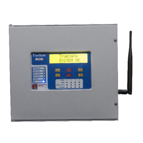
TrueSafe GDS-24-2/4 is a conventional gas detection panel which provides reliable Gas detection, signalling and
protection for commercial, industrial and institutional buildings or small offices. The panel is cost effective and is
available in two variants, 2 input zones and 4 input zones. The panel includes a large 16 x 2 LCD display, local
buzzer, L Ds for, keypad for manual operation and configuration. It is compatible with almost all makes of gas
detectors and heat detectors with potential free outputs, which continuously monitor for trouble and gas condition.
GDS-24-2 Gas detection panel, 24V operated, 2-input zones
GDS-24-4 Gas detection panel, 24V operated, 4-input zones
Figure 1: GDS-24-2 anel
Figure 2: GDS-24-4 anel

Gas Detection System GDS-24-2/4 User and Installation Manual
Page 8 of 30
System Features
•Large 16 x 2 character LCD Display.
•L D indications for various modes on front panel.
•Local buzzer indication for Alarm, fault, and testing operation.
•6 Keys for configuration and program the system.
•Class B Initiating Device Circuits (IDCs) for Gas detectors & heat detectors.
•Testing modes (Walk test)
•Zone Bypass and NAC bypass facility.
•Three fixed Potential Free Relay Contact outputs for alarm, valve control & fault.
•Valve output selectable as “Latched” or “Pulsed”.
•Two level password protection for Admin and user.
•Up to 15 scrolling events capacity.
•24V DC output for powering gas detectors.
•24V DC power supply with built-in battery charger.
•Battery low voltage 23 VDC and battery cut at 22 VDC.
•Stand by battery backup up to 8 hrs.
1.2 Technical Specifications of GDS-24-2
ower Supply 180~264VAC, 47~63Hz
DC Output Voltage 24~27 Volts DC, 1.2 A max
Battery Charging Voltage 27 Volts DC nominal
Battery Charging Current 200mA max
Battery Type For GDS-24-2: 2 x 12VDC, 1.2Ah Sealed Lead Acid Batteries
Number of Gas Detection Zones 2
Available current for Gas Detectors ~ 600 mA
Display Large 16x2 character LCD Display
Sounder (Siren) output rating (one
output)
~ 0.3 Amp
Relay contacts and ratings Three Potential Free Relay Contacts – 1 Fire, 1 Valve Control, 1
Fault (2A Max contact ratings)
Keypad 6 Keys
Operating Temperature 0°C to 50°C
Humidity 5 to 90% RH
Storage Temperature - 10°C to 70°C
Dimensions GDS-24-2: 237mm x 217mm x 42mm (LxHxW)
Enclosure Powder coated metal enclosure
Weight GDS-24-2: 3 Kg approximately without batteries.
Table 1: Technical Specifications of GDS-24-2

Gas Detection System GDS-24-2/4 User and Installation Manual
Page 9 of 30
1.3 Technical Specifications of GDS-24-4
ower Supply 180~264VAC, 47~63Hz
DC Output Voltage 24~27 Volts DC, 3A
Battery Charge Voltage 27 Volts DC nominal
Battery Charging Current ~700 mA
Battery Type For GDS-24-4: 2 x 12VDC, 7Ah Sealed Lead Acid Batteries
Number of Gas Detection Zones 4
Available current for Gas Detectors ~ 1.8 Amp
Display Large 16x2 character LCD Display
Sounder (Siren) output rating (one
output)
~ 0.3 Amp
Relay contacts and ratings Three Potential Free Relay Contacts – 1 Fire, 1 Valve Control, 1
Fault (2A Max contact ratings)
Keypad 6 Keys
Operating Temperature 0°C to 50°C
Humidity 5 to 90% RH
Storage Temperature - 10°C to 70°C
Dimensions GDS-24-4: 440mm x 325mm x 100mm (LxHxW)
Enclosure Powder coated metal enclosure
Weight GDS-24-4: 6 Kg approximately without batteries.
Table 2: Technical Specification of GDS-24-4

Gas Detection System GDS-24-2/4 User and Installation Manual
Page 10 of 30
1.4 Controls and Indications
Figure 2: Controls & Indications for GDS-24-2
Figure 3: Controls & Indications for GDS-24-4
Figure 3 & 4 shows the controls and indications on the GDS-24-2 and GDS-24-4. The details of these are given in
following sections.

Gas Detection System GDS-24-2/4 User and Installation Manual
Page 11 of 30
1.4.1 Controls
Key name assword
protected?
Key function
MENU
OR
Num key ‘1’
Yes •nter main menu list
•Configures system as per requirements
•Use as a sc
OR
•nter numeric values ‘1’ during configuration
SILENCE
OR
Num key ‘2’
Yes
•
Silence the NAC
OR
•nter numeric values ‘2’ during configuration
ENTER
OR
Num key ‘3’
Yes
•
Access the new menu.
•Saves configured data, mode or value of the
system.
OR
•nter numeric values ‘3’ during configuration
‘<’
OR
Num Key ‘4’
Yes •Scroll Left
OR
•nter numeric values ‘4’ during configuration
RESET
OR
Num key ‘5’
Yes •Reset the system
OR
•nter numeric values ‘5’ during configuration
‘>’
OR
Num Key ‘0’
Yes
•
Scroll Right
OR
•nter numeric values ‘0’ during configuration
Table 3: Controls for GDS-24-2/4
1.4.2 LED Indications
No. Indication LED Colour Description
1 System ON Green This indication shows system is Power ON
2 Mains Fail Yellow When Mains Fail Occurs, ON
3 Battery Fault Yellow When Battery is Low OR Battery missing, ON
4
NAC Fault Yellow NAC Fault has been occurred, ON
5 Silence Yellow System has been silenced, ON
7 NAC Fault Yellow NAC Fault has been occurred, ON
8 Twin Alarm Red If any zone is in Alarm condition, ON
9 Zone Alarm Red If zone in Alarm condition, ON
10 Zone Fault/WT Yellow If zone in Fault/WT Mode, ON
11 Zone Bypass Yellow If zone disable, ON
Table 4: LED Indications for GDS-24-2/4

Gas Detection System GDS-24-2/4 User and Installation Manual
Page 12 of 30
1.4.3 LCD Indication
A large 16 x 2 LCD display is used in GDS panel to display various system status fault status, zone Alarm status,
configuration menus & so on. The LCD is mainly used for different indications and for the programming of the
panel listed as below.
•Alarm Indications
•Fault Indications
•Zone modes
•View history events
•Panel Configuration setting
•Change user / admin password
1.4.4 Buzzer Indication
A buzzer provides separate and distinct sounds for Alarm, Faults and Walk Test
•Alarm: Continuous Buzzer ON.
•Fault: 1 sec ON and 5 sec OFF.
•Walk Test: 1 sec ON and 1 sec OFF.

Gas Detection System GDS-24-2/4 User and Installation Manual
Page 13 of 30
2Installation
2.1 Installation recautions
1. Do not attempt to install, service, or operate this unit, until this manual is read and understood.
2. Installation of the panel should be carried out by qualified personnel only.
3. The electronic components within the panel are vulnerable to physical damage and damage by
electrostatic discharges.
4. It is advisable to wear a wrist strap designed to prevent the build-up of static charges within
the body, before handling any electronic circuit boards.
5. Never insert or remove boards or components with the power on.
6.
This system works at 0°C to +50°C and at a relative humidity of 90% RH. However, the useful life of the
system's standby batteries and the electronic components may be adversely affected by extreme
temperature ranges and humidity.
2.2 Mounting the anel
Figure 4: Mounting details of GDS-24-2

Gas Detection System GDS-24-2/4 User and Installation Manual
Page 14 of 30
Figure 5: Mounting details of GDS-24-4
1. The site chosen for the location of the panel should be clean and dry and not subject to shock or vibration.
The temperature should be in the range 0°C to +50°C, the humidity should not exceed 90%.
2. Open the panel door and unplug the power connectors from the bottom side of the power supply. Remove
the three screws holding the plate in position and then remove the complete circuit board and plate.
3. Hold the assembly by gripping the metal plate only and try to avoid touching the circuit board. Place the
plate/circuit board assembly and fixing screws in a safe location to prevent accidental damage.
4. Remove the mains cable connected to the power supply.
5. Remove knock outs from the top of the panel for required cable entries.
6. Using the panel box as a template, mark the position of the top fixing hole, ensuring that the wall is flat at
the chosen location. The top fixing is a keyhole slot and fitting a screw here and hanging the box first will
assist in marking the remaining fixing points.
7. Screws or bolts of a minimum of 5mm diameter and 40mm long must be used to mount the enclosure in
all three mounting positions.
8.
nsure the enclosure and the inner parts of the panel are given sufficient protection during installation.
9. When the installation of all the cables has been completed, clean the interior of the enclosure ensuring all
masonry debris and drilling burrs are removed.
2.3 Battery Installation
1. The GDS-24-2 panel is designed to house maximum two batteries of 12V, 1.2Ah. The GDS-24-4
panel is designed to house maximum two batteries of 12V, 7Ah. The batteries have to be placed
at the bottom right hand corner of the enclosure and held in position by two brackets screwed
to the panel.
2. There is no need to remove the front plate from the panel to install the batteries.
3. After fixing the panel on the wall, place the batteries inside the panel.
4. Make sure that the battery terminals facing the ceiling and not the user.

Gas Detection System GDS-24-2/4 User and Installation Manual
Page 15 of 30
5. BATTERY CONNECTIONS SHOULD BE MADE ONLY AFTER A LYING MAINS OWER TO
THE ANEL.
Figure 6: Battery connections viewed from above

Gas Detection System GDS-24-2/4 User and Installation Manual
Page 16 of 30
3anel Wiring
Following figure shows the internal wiring of GDS-24-2.
Figure 7: Internal Wiring of GDS-24-2
Above figure shows the internal wiring diagram of the panel. The AC Mains connections from external supply are
given to power supply. The power supply generates the 24V DC and battery charging voltages that are given to
connector J2 and J7 of CPU PCB respectively. Mains Fail (MF) connections i.e. C and connections from the
SSM241.2BC are also given to J2.3 (MF) and J2.4 (G) of CPU PCB respectively which is used for detection of AC
fail.
Below figure shows the internal wiring diagram of the panel GDS-24-4. The AC Mains connections from external
supply are given to PCB RASS_1052. Out of two output connections from PCB RASS_1052, one AC mains
connection is given to Power Supply and another mains connection given to PCB RASS_9060. The power supply
generates the 24V DC and battery charging voltages that are given to connector J2 and J7 of CPU PCB
respectively. Two Mains Fail (Mains DI) connections from the PCB RASS_9060 are given to J2 (MF and G) of CPU
PCB which is used for detection of AC fail.

Gas Detection System GDS-24-2/4 User and Installation Manual
Page 17 of 30
Figure 8: Internal Wiring of GDS-24-4
All the external connections to and from the panel are at the top as well as bottom of CPU PCB.
The pin out of J2 and J7 is given below.
Figure 9: J2 & J7 in-out
Connector
No.
Connection Name Description
J2.1 +V 24V DC from Power Supply
J2.2 -V GND from Power Supply
J2.3 MF Mains Fail + connection from power supply C
connector
J2.4 G Mains Fail – connection from power supply
connector

Gas Detection System GDS-24-2/4 User and Installation Manual
Page 18 of 30
J7.1 BAT+ Positive Battery charging connection to battery
J7.2 BAT- Battery charging ground connection to battery
J7.3 B- Battery charging ground from power supply
J7.4 B+ Positive Battery charging voltage from power
supply
Table 5: CPU BOARD BOTTOM J2 AND J7 CONN CTIONS
The pin out of J3, J4 and J12 is given below.
NO C NC NO
C NC NO
C NC
Alarm Valve Control Fault / RST
Figure 10: J4 in-out
Siren Zone - 4 Zone – 3 Zone – 2 Zone - 1
- + - + - + - + - +
Figure 11: J3 in-out
24V DC
+ -
Figure 12: J12 in-out
Connector
No.
Connection Name Description
J12.1 24VDC (+) +24V DC Output for detector supply
J12.2 24VDC (-) Ground
J3.1 Zone 1 + Positive connection for Zone 1
J3.2 Zone 1 - Negative connection for Zone 1
J3.3 Zone 2 + Positive connection for Zone 2
J3.4 Zone 2 - Negative connection for Zone 2
J3.5 Zone 3 + Positive connection for l Zone 3
J3.6 Zone 3 - Negative connection for Zone 3
J3.7 Zone 4 + Positive connection for Zone 4
J3.8 Zone 4 - Negative connection for Zone 4
J3.9 Siren + 24V DC connection for Conventional sounder/siren
J3.10 Siren - Ground connection for Conventional sounder/siren
J4.1 Alarm – NO Normally Open Contact of Alarm Relay
J4.2 Alarm – C Common Contact of Alarm Relay
J4.3 Alarm – NC Normally Closed Contact of Alarm Relay
J4.4 Valve Control – NO Normally Open Contact of Valve Control Relay
J4.5 Valve Control – C Common Contact of Valve Control Relay

Gas Detection System GDS-24-2/4 User and Installation Manual
Page 19 of 30
J4.6 Valve Control – NC Normally Closed Contact of Valve Control Relay
J4.7 Fault / RST – NO Normally Open Contact of Fault/RST Relay
J4.8 Fault / RST – C Common Contact of Fault/RST Relay
J4.9 Fault / RST– NC Normally Closed Contact of Fault/RST Relay
Table 6: J3, J4 and J12 Connections
NOT : Zone 3 and Zone 4 not connected for GDS-24-2.
4Field Wiring Diagram
This section explains the field wiring connections for GDS-24-2 & GDS-24-4.
4.1 Initiating Device Circuit (IDC)
•No. of Initiating circuit : 2/4 Zone
•Type : Class B
•Wire Size : 1.5sqmm armoured FRLS cable
•Operating Voltage : 24 VDC nominal max
•Connector : J3
•Monitoring Device : 4.7 K Ω, 1 W( OL)
•Resistor to be connected
in series with detector : 820 Ω, 1 W.
Figure 13: GDS-24-2/4 Typical Zone Connections
Total available Current for connecting Gas Detectors is 600 mA for GDS-24-2 and 1.8 Amp for GDS-24-4.
xample:
1
] TS21I Gas detector requires 250 mA current in High Alarm condition, thus we can connect
maximum 2 TS21I gas detectors to GDS-24-2 and maximum 7 TS21I gas detectors to GDS-24-4.

Gas Detection System GDS-24-2/4 User and Installation Manual
Page 20 of 30
2] TS12CLR Gas detector requires 100 mA current in High Alarm condition, thus we can connect
maximum 6 TS12CLR gas detectors to GDS-24-2 and maximum 18 TS12CLR gas detectors to GDS-24-
4.
4.2 Siren Circuit
There is one Siren circuit on the GDS panel. It is also known as Notification Appliance Circuit (NAC).
Figure 14: Siren Typical Connections
NAC
•No. of NAC : 1 circuits
•Type : Class B
•Output Voltage : 24V
•Current : 300 mA max for GDS-24-2
450 mA max for GDS-24-4
•Terminals : J3
•Wire Size : 1.5sqmm armoured FRLS cable
•OL : 4.7k ohm, 1 W
4.3 Relay Outputs
NO C NC NO
C NC NO
C NC
Alarm Valve Control Fault / RST
There are three relay outputs with potential free contacts:
1. Alarm Relay: This relay is activated when the panel detects an alarm from the detectors connected to its
zones.
2. Valve Control Relay: The 24V supply to the valve can be routed through the potential free contacts of
this relay. The valve control relay operation is configurable as Pulsed type or Latchable type through
keypad. In case of an alarm detected by the panel, the relay will turn ON for 3-4 seconds in Pulsed mode
and then turn-off. In case of Latchable mode, the relay will remain ON until the alarm is present or the
panel is reset to clear the alarm. By default, the valve control is set at Pulsed mode. This mode can be
changed to Latchable mode by switching OFF the panel and switching ON. During switching ON, the ‘4’ &
‘0’ keys should be pressed together to change the mode of valve control relay.
This manual suits for next models
1
Table of contents
Other Vighnaharta Fire Alarm manuals
Popular Fire Alarm manuals by other brands

bolid
bolid S2000-IP-03 instruction manual

Honeywell
Honeywell Silent Knight IntelliKnight 5820XL Installation and operation manual

Fike
Fike CIE-A-200 user manual

Simplex
Simplex SafeLINC 4100 installation manual

Teledata
Teledata SF109 quick start guide

Honeywell
Honeywell NOTIFIER AM-8000 installation manual