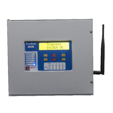
Vighnaharta Master Control Unit User manual

Page 1 of 6
MCU
_1
-
I/P_
User Manual
V
1
.
0
Vighnaharta Technologies Pvt. Ltd.
Formerly Known as Reality Automation & Security System Pvt Ltd
2nd Floor , Karanjakar Industrial Estate, Sr.No 11/11, Nanded Gaon, Pune
Phone
no.: 91 20 32922630 / 32921306 Fax: 91 20 24339628.
Website: http://www.vighnaharta.in
Prepared by: HC
Approved By:
Doc No.: RASS/R&D/
Master Control Unit
1
_UM_1_0
Rev No.: 1_0
Eff. Date: 14/10/2019
USER MANUAL
FOR
Master Control Unit
VERSION 1.0

Page 2 of 6
MCU
_1
-
I/P_
User Manual
V
1
.
0
Table of Contents
1.Overview.................................................................................. Error! Bookmark not defined.
Salient Features .................................................................................................................... 3
2.Technical Specifications ......................................................................................................... 3
3.Installation Instructions ......................................................................................................... 4
Pre-installation Checklist ................................................................................................. 4
Locations to be avoided for installing Master Control Unit .................................................... 4
4.Operation ................................................................................. Error! Bookmark not defined.
5. Wiring Diagram .................................................................................................................... 5
6. Do’s & Don’ts When Fire Occurs .......................................................................................... 6
7. Warranty .......................................................................................................................... 6

Page 3 of 6
MCU
_1
-
I/P_
User Manual
V
1
.
0
1. Overview
FIRE SUPPRESSION MONITOR SYSTEM is specially designed for monitoring the output of Fire detectors.
When Fire level above predefined limit is detected then a signal from Fire detector triggers the Master
Control Unit system, Master Control Unit provides audio, visual alarm indication.
Salient Features
Audio and visual indications
Auto silence of sounder: Sounder becomes OFF for 30 seconds after 3 minutes and again becomes ON.
This feature is for protecting the sounder from over-heating and damage.
Two PFC outputs for interfacing the other systems.
LED Indications for: MAINS ON, SYSTEM HEALTHY,GAS Release 1 ALARM,SILENCE
Easy installation, operation and maintenance free
MS sheet housing and powder coated enclosure.
2. Technical Specifications
Electric specification
Operating Voltage 220V AC, 50Hz
Voltage tolerance 10%
Power supply output Voltage 12V/2A
Indication LED Environmental Specification
Operating Temperature 0°C-+50°C
Humidity 5% to 90%R.H. Non-Condensing

Page 4 of 6
MCU
_1
-
I/P_
User Manual
V
1
.
0
3. Installation Instructions
Pre-installation Checklist
Ensure that you have the following items with Master Control Unit
Master Control Unit
User manual
Test Report
Locations to be avoided for installing Master Control Unit
In an enclosed space (for example, inside a cupboard)
Places where water can splash on the unit
Should not install near heating or cooking appliances.
4. Operation
Sr. No
Parameter
Condition
Status
1
Normal Condition
When digital inputs are
closed. (Fire is below
pre-defined level)
LEDs
1) Mains ON LED=ON
2)System Healthy LED=ON
3)GAS Release 1 Alarm LED=OFF
4) Relay LED=OFF
Hooter with Flasher=OFF
2
When
digital input
1 is open
Digital input 1 is
opened
LEDs
1) Mains ON LED=ON
2)System Healthy LED=OFF
3)GAS Release 1 Alarm LED=ON
4) Relay LED=ON
Hooter with Flasher=ON
Silence Switch:
Silence switch can be used to silence the alarm triggered by Master Control Unit. If the user press silence
switch in case of Fire detect then it will be considered as acknowledgement of alarm.
Relay Output:
The relay output can be used to trigger any external device such as siren, dialer or input for security
system.

Page 5 of 6
MCU
_1
-
I/P_
User Manual
V
1
.
0
5. Wiring Diagram
A
PFC
Output ON 1 NO
B
PFC
Output ON 1 Common
C
PFC
Output ON 1 NC
D
PFC
Output ON 2 NO
E
PFC
Output ON 2 Common
F
PFC
Output ON 2 NC
G
DC+12V
H
DC
-
12V
I
Flasher
Sounder +ve
J
Flasher
Sounder
-
ve
K
NA
L
NA
M
Digital
Input 1 +ve
N
GND

Page 6 of 6
MCU
_1
-
I/P_
User Manual
V
1
.
0
6. Do’s & Don’ts When Fire Occurs
Do’s:
If the Fire is severe, it is very dangerous for anybody to enter the premises.
If there is a minor/moderate Fire - Turn off the knob, regulators .
Open all doors & windows.
Don’ts:
Do not panic
Do not OFF/ON any electrical switch.
7. Warranty
Realty Automation and Security Systems PVT. Ltd products are warranted for 12 months subjected to
following terms and condition.
This limited warranty covers defects in materials and workmanship in this product, it does not cover
any malfunction occurred due to transportation, wrong material handling practice, wrong wiring,
voltage and current fluctuations etc.
Consumable parts such as cables, cords, stickers etc. are not subjected to warranty.
This limited warranty covers only the original purchaser of the product. The limited warranty is not
transferable to subsequent owners or purchasers of this product
The limited warranty does not assume the risk of loss during shipment.
Warranty does not include fuses, disposable batteries or the routine replacement of parts due to
normal wear and tear of the product
Product warranty void if
Any damage or defects attributable to repair of the product by any person other than an authorized
dealer, or the installation of unapproved parts on the product
LCD/LED crushed or bleeding
War page to the main PCB as a result of crushing
Fluid ingress as a result of submergence beyond the I.P rating specification
If not followed: proper storage, installation, calibration, use, maintenance and compliance with the
product manual instructions and any other applicable recommendations of Realty Automations and
Security Systems PVT. Ltd
Limited Warranty Liability: If in case, due to any reason if the product does not function as per the
desired specifications, then the manufacturer will not be responsible for any liability/damages arises
because of its non-function. In any case manufacturer will not be able to pay the compensation beyond
the selling price of manufacturer, which needs to be shown in terms of selling/buying invoice in terms of
Indian Rupees. For exports warranty claims, invoiced date should be considered for deriving rate of INR
= USD. In any case warranty claim will not be accepted beyond unit value of the products sold as per the
invoice. Manufacturer/seller does not take any responsibility of any damages which arises because of
timely non-function of the product.
To and fro transportation cost till the centre/factory at Pune to be borne by the customer.
For all warranty claims customer need to produce invoice/warranty certificate.
Table of contents
Other Vighnaharta Fire Alarm manuals
Popular Fire Alarm manuals by other brands

Teknim
Teknim TFS-3191 Installation & operating guide

Advanced
Advanced MxPro4 Series Installation Sheet & Quick Reference Guide

Siemens
Siemens HFPT-11 Installation instructions manual

Hochiki
Hochiki IFD-E user manual

ELOTEC
ELOTEC Confire manual

System Sensor
System Sensor 7100XE FAAST Installation and maintenance instructions

Radionics
Radionics D7024 operating instructions

Aritech
Aritech 2X-F2-FB2-S-32 Quick operation guide

Federal Signal Corporation
Federal Signal Corporation 350 installation instructions

Abus
Abus FUAT50020 manual

Brooks
Brooks ALARM 2000 Site Manual

Siemens
Siemens Cerberus Pyrotronics CP2297 installation instructions