manuals.online logo
Brands
  1. Home
  2. •
  3. Brands
  4. •
  5. Vigilant
  6. •
  7. Smoke Alarm
  8. •
  9. Vigilant V-PCOS Assembly instructions

Vigilant V-PCOS Assembly instructions

© 2013 UTC Fire & Security Americas Corporation, Inc. 1 / 4 P/N 3102074-EN • REV 02 • ISS 09MAY13
V-PCOS Intelligent Photoelectric Smoke
Detector with CO Sensor Installation Sheet
Carbon monoxide alarm procedure
WARNING: The carbon monoxide (CO) alarm indicates the
presence of CO, which can kill you. If the alarm signal sounds
four times, pauses for five seconds, and then repeats the
pattern:
1. Move to fresh air immediately — outdoors or by an open
door or window. Check that all persons are accounted for.
Do not reenter the premises or move away from the open
door or window until emergency services responders have
arrived, the premises have been aired out, and your
detector remains in normal condition.
2. Call emergency services, the fire department, or 911:
Phone:
Information about carbon monoxide
WARNINGS
•Read these installation instructions in their entirety before
proceeding. Leave these instructions with the owner/user
of this CO detection equipment.
•This product is intended for use in indoor locations of
dwelling units. It is not designed to comply with
Occupational Safety and Health Administration (OSHA)
commercial or industrial standards.
•The detector only indicates the presence of CO gas at the
detector. Carbon monoxide gas may be present in other
areas.
•Failure to properly install, test, and maintain a CO detector
may cause it to fail, potentially resulting in loss of life.
•Installation of this detector is not a substitute for proper
installation, use, and maintenance of fossil fuel-burning
appliances, including appropriate ventilation and exhaust
systems.
•To reduce the risk of CO poisoning, test the detector
operation when not in use for 10 days or more.
•This detector does not operate without electrical power. As
fires frequently cause power interruption, discuss further
safeguards with the authority having jurisdiction (AHJ).
•Do not paint the detector.
Notes
•Regulatory code may require that the system generate a
three-pulse temporal code (TC3) for fire alarms and a four-
pulse temporal code (TC4) for CO alarms.
•The CO sensor is calibrated at the factory. CO sensitivity
is set to conform to UL 2034 requirements and cannot be
changed by the user. See “Regulatory information” on
page 4 for specific sensitivity values.
•Connect this detector only to a UL Listed control panel
capable of differentiating between alarm signals (fire,
burglary, CO, etc.) and providing distinct identification for
each.
•To reduce the likelihood of nuisance alarms, ventilate
accommodation spaces when using household cleaning
supplies or similar contaminants. If a detector has been
exposed to such contaminants, test it promptly afterwards.
Symptoms of CO poisoning
The following symptoms related to CO poisoning should be
discussed with all occupants of the protected site.
Mild exposure: Slight headache, nausea, vomiting, fatigue,
runny nose, sore eyes (often described as "flu-like" symptoms).
Medium exposure: Severe throbbing headache, dizziness,
drowsiness, confusion, fast heart rate.
Extreme exposure: Unconsciousness, brain damage,
convulsions, cardiorespiratory failure, death.
Many cases of reported CO poisoning indicate that while
victims are aware they are not well, they become so
disoriented that they are unable to save themselves by either
exiting the building or calling for assistance. Young children
and pets may be the first affected.
2 / 4 P/N 3102074-EN • REV 02 • ISS 09MAY13
CO sources
The CO sensor in this detector is designed to detect carbon
monoxide gas from any source of combustion. It is not
intended to detect fire, smoke, or any other gas. Potential CO
sources include fuel-fired appliances (e.g., space heater,
furnace, water heater, range, oven, clothes dryer); other
sources of combustion (e.g., kerosene-burning stove or heater,
or gas log fireplace); or internal combustion engines.
In addition, excessive exhaust spillage or reverse venting of
fuel-burning appliances can produce dangerous transient
levels of CO. This can be caused by external conditions:
•Wind direction, velocity, or a combination of both,
including high gusts of wind or insufficient draft in vent
pipes
•Temperature inversions that can trap exhaust gases near
the ground
•Negative pressure differential resulting from the use of
exhaust fans
•Simultaneous operation of several fuel-burning appliances
competing for limited internal air
•Vent pipe connections vibrating loose from dryers,
furnaces, or water heaters
•Obstructions in vent pipes or unconventional vent pipe
designs which can amplify the above situations
•Poorly designed or maintained chimneys and/or vents
•Extended operation of unvented fossil fuel-burning devices
(range, oven, fireplace, etc.)
•Idling cars in an open or closed attached garage, or near
the premises
General limitations of CO detectors
This detector is designed to protect individuals from the acute
effects of CO exposure. It will not fully safeguard individuals
with specific medical conditions. People with special medical
problems should consider using specialized detection devices
with less than 30 ppm (parts per million) alarming capabilities.
If in doubt, consult a medical practitioner.
If the unit is in trouble or at the end of its life, it may not sense
CO and cannot be relied upon to monitor CO levels. Replace
the CO module every six years from the date of manufacture or
when the control panel indicates a sensor end-of-life condition,
whichever comes first.
A detector installed outside a bedroom may not awaken a
sleeper. Normal noise due to stereos, television, etc. may also
prevent the detector from being heard if distance or closed or
partly closed doors muffle the sounder. This unit is not
designed for the hearing impaired.
CO detectors are not a substitute for life safety. Though these
detectors will warn against increasing CO levels, we do not
warrant or imply in any way that they will protect lives from CO
poisoning. They should only be considered as an integral part
of a comprehensive safety program.
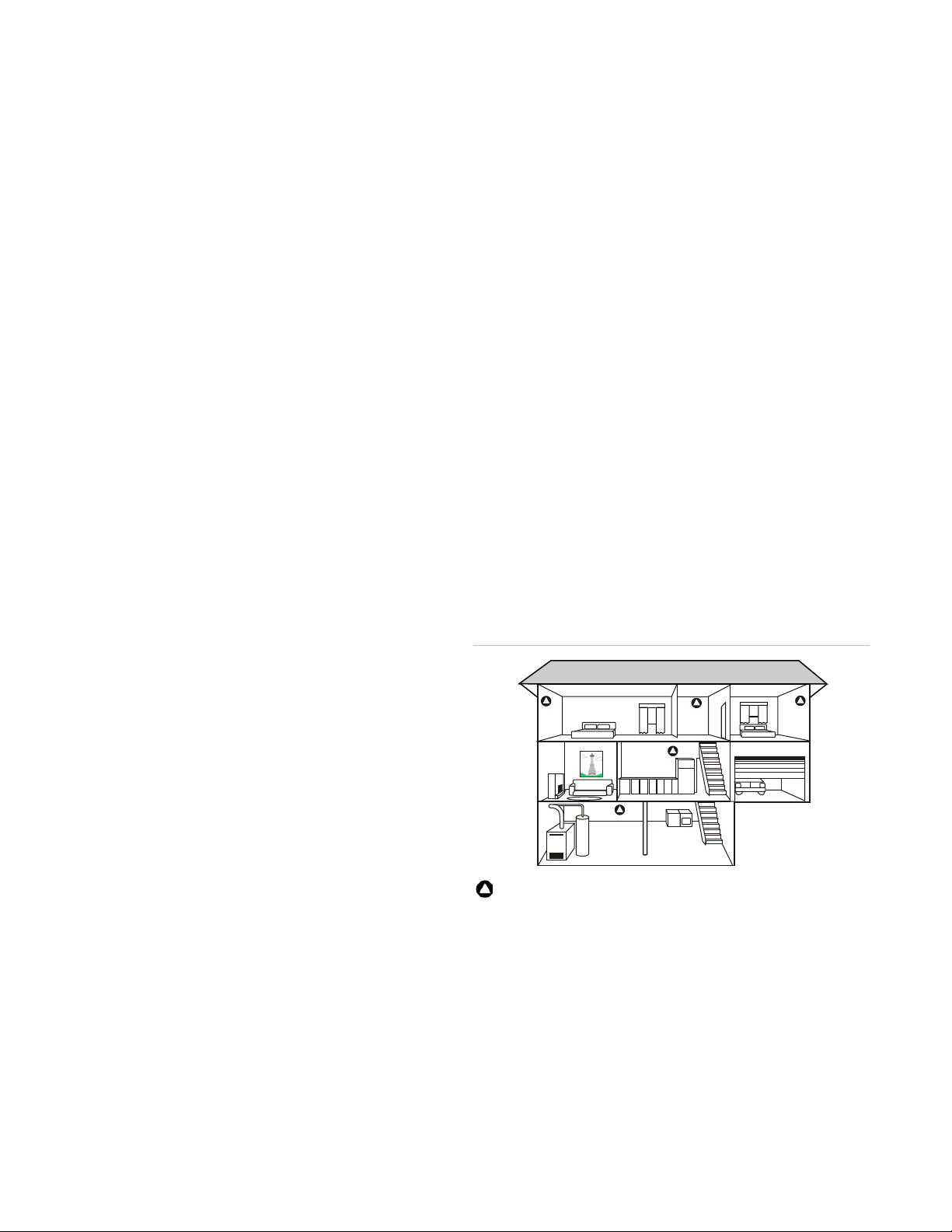
Detector locations
Selecting a suitable location is critical to the operation of CO
detectors. Figure 1 shows appropriate detector locations.
Install detectors according to applicable codes and standards.
Place wall-mounted detectors at least 5 ft. (1.5 m) up from the
floor. For ceiling mounted applications, place detectors at least
1 ft. (0.3 m) from any wall. For combination detectors, follow
the spacing requirements for each sensor. Refer to the control
panel’s application bulletin for the sensor spacing
requirements.
The recommended CO detector locations are:
•Outside each separate sleeping area in the immediate
vicinity of the bedrooms (including areas such as hotel
rooms and dorm rooms)
•On every occupiable level of a dwelling unit, including
basements, but excluding attics and crawl spaces
•Centrally located on every habitable level of the building
and in every HVAC zone based on an engineering
evaluation considering potential sources and migration of
carbon monoxide
•On the ceiling in the same room as permanently installed
fuel-burning appliances
•In any area required by local building codes, legislation, or
the AHJ
•In a suitable environment per the detector specifications
(see “Specifications” on page 4 for details)
•On a firm, permanent surface
Do not install the CO detector:
•Within 5 ft. (1.5 m) of any cooking appliance
•Within 10 ft. (3 m) of a fuel-burning appliance
•Near air conditioners, heating registers, or any other
ventilation source that may interfere with CO gas entering
the detector
•Where furniture or draperies may obstruct the airflow
•In a recessed area
Figure 1: Recommended CO detector locations
Recommended CO detector location
Description
The model V-PCOS Intelligent Photoelectric Smoke Detector
with CO Sensor is an intelligent device that uses an optical
sensing chamber to detect smoke, and a CO sensor to detect
carbon monoxide from any source of combustion. The detector
analyzes the smoke and CO sensors independently to
determine whether to initiate a fire alarm, a life safety CO
alarm, or both.
P/N 3102074-EN • REV 02 • ISS 09MAY13 3 / 4
LED indicator. The LED indicator (see Figure 2) displays the
following states:
•Normal: Green LED indicator flashes, no action.
•Alarm/active: Red LED indicator flashes, evacuate the
area.
•Stand-alone alarm: Red LED indicator turns on, evacuate
the area.
Sensor end-of-life indicator. The detector signals a
"COMMON TRBL ACT" condition on the control panel when
the CO sensor reaches its end of life. Pressing the Details
button on the control panel displays "END OF LIFE ACT"
providing verification that it is an end-of-life trouble of the CO
sensor. This trouble remains active until the sensor is replaced,
even if the panel is reset. See “Replacements” on page 4.
Figure 2: V-PCOS features
(1) Tamper-resist lever arm on base
(2)
Access slot for tamper-resist mechanism
(3) LED indicator
Installation
Notes
•This detector does not sense fires in areas where smoke
cannot reach the detector. Smoke from fires in walls,
roofs, or on the opposite side of closed doors may not
reach the detector.
•This detector does not detect oxygen levels or flames. Use
this device as part of a broad-based life safety program
which includes a variety of information sources pertaining
to heat and smoke levels, extinguishment systems, visual
and audible devices, and other safety measures.
•Photoelectric detectors have a wide range of fire-sensing
capabilities and are best suited for detecting slow,
smoldering fires.
•To ensure proper operation, store the detector within the
recommended ranges. Allow the detector to stabilize to
room temperature before applying power.
•The dust cover (supplied) must remain on the detector
during installation and be removed prior to commissioning
and service. The dust cover is not a substitute for
removing the detector during new construction or heavy
remodeling.
•Do not install detectors until after final construction
cleanup (unless otherwise specified by the AHJ).
•Do not use smoke detectors with detector guards unless
the combination has been evaluated and found suitable.
•Install per NFPA 72 National Fire Alarm and Signaling
Code, NFPA 720 Standard for the Installation of Carbon
Monoxide (CO) Detection and Warning Equipment, and
UL 2075 Standard for Gas and Vapor Detectors and
Sensors.
•Upon completion of the original installation and following
any modifications or additions to the system, perform a
calibrated sensitivity test per NFPA code. The Signature
Series can perform this test and generate a system
sensitivity report.
•To permanently disable the tamper-resist mechanism prior
to placing the detector in difficult to reach locations, break
and remove the plastic lever arm from the base. See
Figure 2.
To install the detector:
1. Install and wire the base, as described on the installation
sheet supplied with the base.
2. Remove the serial number label from the detector and
attach it to the project documentation.
3. Attach the detector to the base by rotating the detector
clockwise until it snaps into the locked position.
4. If required by the AHJ or local codes, affix the supplied CO
Warning Label (P/N 10634757) in proximity to the
detector.
Testing
Before testing, notify the proper authorities that the fire alarm
system is undergoing maintenance and will be temporarily out
of service.
Test each sensor in the detector. In the following steps, xxx
indicates a variable related only to marketplace.
Make sure the SIGA2 Testifire Adapter Assembly (model
SIGA2-TSTSPACER) is installed in the Testifire detector tester
before testing. Refer to the SIGA2 Testifire Adapter Assembly
Installation Sheet (P/N 3101942) for further details.
Note: If the CO sensor is programmed as an alarm point, it
must comply with the requirements of NFPA 720.
To perform an initial installation test:
1. Visually inspect each detector and verify that it is installed
in the correct location. Make sure that factors not apparent
in the plans do not adversely affect the detector.
2. Remove the detector from its base and verify that the
proper detector address, trouble signals, and messages
are reported.
3. If wired for Class A operation, verify that the detector
continues to operate first with SLC_IN disconnected, and
then with SLC_OUT disconnected. (Refer to the
installation sheet for the base.)
4. Place a momentary ground fault on the SLC circuit to
verify operation of the ground fault detection circuitry.
(3)
(1)
(2)
4 / 4 P/N 3102074-EN • REV 02 • ISS 09MAY13
5. Run a system detector sensitivity report on all detectors
and verify that readings fall within acceptable limits.
6. Perform a sensor function test, as described below.
To perform CO sensor function tests:
1. Use the fire alarm control panel to put the detector into
accelerated response mode. (Refer to the panel technical
reference manual for instructions.)
2. Activate the CO sensor using SDI LLC model Solo C6-xxx
CO aerosol spray without covering the head, or using the
Testifire detector tester per the manufacturer’s
instructions.
To perform smoke sensor function tests:
1. If desired, use the fire alarm control panel to put the
detector or zone into a service group for testing. (Refer to
the panel technical reference manual for instructions.)
2. Activate the smoke sensor using No Climb Products
model CHEK02-xxx smoke aerosol spray, a smoke
generator, or the Testifire detector tester per the
manufacturer’s instructions.
Maintenance
To ensure proper operation, plan maintenance in accordance
with the requirements of the AHJ. Refer to NFPA 72 National
Fire Alarm and Signaling Code.
Refer to application bulletin P/N 3101109 for additional
information and cleaning instructions.
Replacements
Smoke chamber. Replace the smoke chamber whenever
cleaning the detector does not restore the panel to normal
conditions. Replace with model number 2-SPRC2, using
installation sheet P/N 3101596.
CO module. Replace the CO module every six years from the
date of manufacture or when the control panel indicates a
sensor end-of-life condition, whichever comes first. Replace
with model number 2-CORPL, using installation sheet
P/N 3101589.
Specifications
Operating voltage
15.20 to 19.95 VDC
Current
Normal operating
Alarm
Stand-alone alarm
70 µA
70 µA
18.5 mA
Vibration level
10 to 35 Hz, with an amplitude of
0.01 in.
Wall mount distance from
ceiling
12 in. (305 mm) max.
Compatible b
ases
Standard
Relay
Isolator
Audible
GSA-SB, GSA-SB4
GSA-RB, GSA-RB4
GSA-IB, GSA-IB4
GSA-AB4G, GSA-SBT [1]
Compatible detector testers
[2] Testifire 1000, Testifire 2000
Operating environment
Temperature
Relative humidity
32 to 120°F (0 to 49°C)
0 to 90% noncondensing
Storage temperature
−4 to 140°F (−20 to 60°C)
Environmental compensation
Automatic
[1] Required for those installations that must provide separate CO
(TC4) and fire (TC3) patterns from the sounder base.
[2] Requires the SIGA2-TSTSPACER Testifire adapter assembly.
Regulatory information
Manufacturer
Edwards, A Division of UTC Fire & Security
Americas Corporation, Inc.
8985 Town Center Parkway, Bradenton, FL
34202, USA
Year of
manufacture
The first two digits of the date code (located on
the product identification label) are the year of
manufacture.
UL
smoke
sensitivity range
0.85 to 4.0%/ft. (2.7 to 12.5 %/m) obscuration
UL
CO alarm level 70 ppm 60 to 240 minutes [1]
North American
standards
ANSI/UL 268, ANSI/UL 2075
Note: This detector has been evaluated to the CO
alarm sensitivity limits of ANSI/UL 2034.
FCC compliance
This device complies with part 15 of the FCC
Rules. Operation is subject to the following two
conditions: (1) This device may not cause harmful
interference, and (2) this device must accept any
interference received, including interference that
may cause undesired operation.
[1] Sensitivity per ANSI/UL 2034
Contact information
For contact information, see www.vigilant-fire.com.

Other Vigilant Smoke Alarm manuals

Vigilant V-PS Assembly instructions

Vigilant

Vigilant V-PS Assembly instructions

Vigilant V-PHS Assembly instructions

Vigilant

Vigilant V-PHS Assembly instructions

Popular Smoke Alarm manuals by other brands

First Alert PC1210 user manual

First Alert

First Alert PC1210 user manual

SILENT KNIGHT IFP-2000 Installation and operation manual

SILENT KNIGHT

SILENT KNIGHT IFP-2000 Installation and operation manual

SimpliSafe CA002 owner's manual

SimpliSafe

SimpliSafe CA002 owner's manual

Weller LASERLINE 150 Translation of the original instructions

Weller

Weller LASERLINE 150 Translation of the original instructions

Tanda TX7120 Installation and operation manual

Tanda

Tanda TX7120 Installation and operation manual

Cavius 4002-001 user guide

Cavius

Cavius 4002-001 user guide

FIBARO FIBEFGSD-002 quick start guide

FIBARO

FIBARO FIBEFGSD-002 quick start guide

SANJIANG A9036T manual

SANJIANG

SANJIANG A9036T manual

Kidde GSA-PS Installation sheet

Kidde

Kidde GSA-PS Installation sheet

Siemens DOW1171 Installation

Siemens

Siemens DOW1171 Installation

Universal Security Instruments MIC1509S manual

Universal Security Instruments

Universal Security Instruments MIC1509S manual

x-sense XS03 user manual

x-sense

x-sense XS03 user manual

Almaks STD-200-CA1 installation manual

Almaks

Almaks STD-200-CA1 installation manual

SILENT KNIGHT SD505-DUCT installation instructions

SILENT KNIGHT

SILENT KNIGHT SD505-DUCT installation instructions

MGC MIX-4020 Installation and maintenance instructions

MGC

MGC MIX-4020 Installation and maintenance instructions

Hochiki SLR-24 installation instructions

Hochiki

Hochiki SLR-24 installation instructions

Gentex 7109CS installation instructions

Gentex

Gentex 7109CS installation instructions

Universal Security Instruments MDS300 instructions

Universal Security Instruments

Universal Security Instruments MDS300 instructions

manuals.online logo
manuals.online logoBrands
  • About & Mission
  • Contact us
  • Privacy Policy
  • Terms and Conditions

Copyright 2025 Manuals.Online. All Rights Reserved.