manuals.online logo
Brands
  1. Home
  2. •
  3. Brands
  4. •
  5. Viking
  6. •
  7. Card Reader
  8. •
  9. Viking PRX-2 User manual

Viking PRX-2 User manual

PRODUCT MANUAL
Designed, Manufactured and Supported in the USA
COMMUNICATION & SECURITY SOLUTIONS
Features
The model PRX-2 is designed to be mounted directly to
standard single-gang wall box, and integrates both a
125KHz proximity card reader and keypad into a single-
unit making it ideal for applications requiring an access
credential and/or personal identification number (PIN).
The proximity card reader and keypad of the PRX-2 are
both capable of transmitting data in 26-Bit Wiegand
format, making it compatible with any of the Wiegand
equipped Viking entry controllers. The keypad is based
upon cutting-edge, non-mechanical, capacitive
technology, which, unlike membrane keypads, includes no
moving parts prone to early failure. Advanced keypad
enhancements include fully potted circuit board (EWP),
keys with blue LED backlighting, raised key outlines and
pip on the 5-key.
The PRX-2 delivers non-contact read ranges up to 6
inches (152 mm), and operates from 5 to 14 VDC.
Mounting is simplified with horizontal and vertical
mounting slots, which allow the reader to be conveniently
adjusted and leveled. Concealing the mounting hardware,
the PRX-2 ships with both Black and Ash (Off-White)
covers standard.
• Read range of up to 6 inches using proximity cards, 3
inches with PRX-FOB
• Reader Format: 26-bit Wiegand
• Keypad formats: 8-bit burst (default) and 26-bit Wiegand
• Technologies supported: Viking PRX-C, PRX-C-ISO,
PRX-FOB, LRT-4 certain legacy HID® proximity
protocols* and certain AWID 125Khz proximity
protocols**
• Designed for outdoor use, the PRX-2 comes standard
with Enhanced Weather Protection (EWP) (DOD# 859)
• PRX-2 is designed to meet IP66 Ingress Protection
Rating (see DOD# 859)
• Mounts to a standard single gang electrical box
• Pigtail connection for easy installation
• Red LED shows activity
• Beep tones acknowledge key strokes
• Programmable Facility Code stored in non-volatile
memory (no batteries required)
• Can be mounted directly to a metal surface
• CE marked
* HID and the HID logo are registered trademarks of HID Global
Corporation, an ASSA ABLOY company. All other trademarks
are the property of their respective owners.
** AWID is a trademark of Applied Wireless Identification Group.
Power: 5-14V DC 50mA - average, 115mA - peak.
Dimensions: 4.6” x 3.1” x 0.7” (117mm x 77mm x 18mm)
Shipping Weight: 0.25 lbs (0.11 kg)
Environmental: -40°F to 150°F (-40°C to 65°C) with up to
100% humidity
Connections: 8” long pigtail leads, 22 gauge
Read Range: Up to 6 inches (152 mm)
Input Voltage: +5 to 14 VDC
Current Draw: 30 mA minimum, 50 mA typical, 115 mA peak
LED Indicator: Four-State Standard (Red, Green, Amber,
and Off)
Audio Tone: Standard
Frequency: 125 KHz excitation
Reader Formats: Wiegand (26-bit Industry Standard) and
ABA Track II magnetic stripe (clock/data)
Keypad Formats: 8-Bit Burst (default) and 26-Bit Wiegand
PRX-2
125KHz Proximity Card
Reader with Keypad
January 14, 2019
Compatible Products
Specifications
VIKING
www.VikingElectronics.com
Information: 715-386-8861
The PRX-2 comes equipped with Enhanced Weather
Protection (EWP) for outdoor installations where the unit
is exposed to precipitation or condensation. The PRX-2
features sealed connections, as well as an epoxy potted
circuit board. For more information on Enhanced Weather
Protection (EWP), see DOD# 859.
125KHz Proximity Card Reader with Built-In Keypad
Model Description DOD#
AES-2000
Accessible Entry System
202
AES-2005
Accessible Video Entry System
204
C-4000
Apartment/Office Entry Controller
164
ES-1
Stand Alone Keyless Entry System
193
ES-3
Entry System Door Controller
195
K-1200-IP
VoIP Entry phone, Keypad, 12 Number Auto
Dialer, Keyless Entry
271
K-1700-IP
VoIP Entry phone, Keypad, Auto Dialer, Keyless
Entry
253
K-1900-8-IP
VoIP Entry Phone with Handset and Keypad
361
PRX-C
Proximity Card
198
PRX-C-ISO
Thin Proximity Card
198
PRX-FOB
Proximity Key Fob
198
LRT-4
Long Range Transmitter with Proximity Module
226
Requirements
Wiring
Installation
Cable Requirements: The PRX-1 can operate at up to *500 ft (244 m) of cable, using seven-conductor, shielded, stranded cable. Per the
Security Industry Association’s Wiegand specification, AWG 24 (such as Belden 9537) is the minimum gauge required for data transfer in a 500-
foot run length. However, the proper wire gauge to use must be determined by the current draw requirements of the reader, the length of the
cable run, and the voltage applied to the reader.
If the reader is to be operated at 5 VDC, 5 VDC must be available at the reader (long cable runs have a voltage drop due to the resistance in
the cable). A larger gauge of wire (having less resistance) or a separate power supply near the reader may be required to ensure 5 VDC is
available at the reader.
Grounding: Shield (drain) continuity must run from the reader to the access panel. Shield (drain) and reader ground must be tied together at
the access panel and connect to an earth ground at one point.
Power: The PRX-2 may be powered by the access panel. As such, the reader is powered on when the access panel is powered on. However
the best case is to power the reader by a separate, linear power supply.
Voltage: 5 to 14 VDC Note: For maximum read range, a minimum of 12VDC is recommended.
FleaPower
TM
Control Line: The PRX-2 can be placed in a special lower power mode by pulling the purple colored fleaPower Control Line low.
This special low power mode reduces the average power required by the reader.
* Note: When used with a Viking Entry System/Controller, see the Entry System’s Product Manual for the maximum wire run length.
Note 1: Read range is stated in a clean RF and electrical environment using Viking proximity cards presented parallel to the reader surface
with the reader operating at 12 VDC. Read range may be affected by local installation conditions. Range will be less when mounting to metal.
Note 2: For user orientation in non-illuminated environments the 5-key is always illuminated.
Note: If powering the reader from
its own power supply, the negative
lead of the power supply must be
connected to the BLACK lead on
both the reader and the controller.
To Viking Product
(Keep unused leads
from shorting)
Earth Ground
IMPORTANT: Electronic devices are
susceptible to lightning and power station
electrical surges from both the AC outlet
and the telephone line. It is recommended
that a surge protector be installed to protect
against such surges.
Operation
• 8-Bit Burst (factory default setting)
• 26-Bit Wiegand
The proximity reader and keypad portions of the PRX-2 both share the Wiegand data lines. Specifically keypad data is transmitted in either an
8-Bit Burst (default) or 26-Bit Wiegand data format.
A. Keypad Output Formats
B. Keypad Operation: 26-Bit Wiegand Output
(set unit to this mode to be compatible with Viking products)
C. Keypad Operation: 8-Bit Burst Output (factory default)
D. PIN 65535
E. Keypad Format Tables
26-Bit Wiegand Format Table 8-Bit Burst Format Table
• For user orientation in non-illuminated environments the 5-key
is always illuminated.
• Card presentation or a key press illuminates the keypad for
approximately 20 seconds. Further, each key press generates
a single beep and LED flash from the PRX-2.
• The non-mechanical capacitive technology utilized by the PRX-2 is
optimized for use with a bare finger.
• For best operation when entering a PIN it is recommended that the user’s
finger be physically lifted from the keypad between key depressions.
• Only one key can be pressed at a time.
PIN 65535 is normally used as an error code. The PRX-2 will transmit this code to the host when:
• The “#” key is pressed without any preceding digits.
• The “0” key is pressed any number of times before pressing the “#” key.
• Entering the PIN 65535, or any PIN greater than 65535.
While in the 8-Bit Burst mode each key press results in the PRX-2 transmitting 8-bits of data to the host according to the table in section
Ebelow. To return the PRX-2 to the 8-Bit Burst mode of operation:
1. Cycle power to the reader, and then verify the reader is powered on.
2. Present the Wiegand Keypad Data Mode control card to the reader. The reader beeps four times.
3. Press the “#” key. The reader beeps four times to indicate programming mode has ended.
While in the 26-Bit Wiegand mode the user’s PIN is outputted by the PRX-2 as the ID Number portion of a 26-Bit Wiegand message. As
such PINs can range from 0 to 65534, with 65535 normally reserved as an error code. The facility code is programmed into the reader at
set-up, while parity is calculated by the reader. The data comprising the 26-Bit Wiegand message is transmitted to the host only when the
“#” key is pressed according to the table in section Ebelow.
To set-up the PRX-2 in the 26-Bit Wiegand mode of operation:
1. Cycle power to the reader, and then verify the reader is powered on.
2. Present the Wiegand Data Mode control card to the reader. The reader beeps four times and enters Facility Code programming mode.
3. Enter 0 (Facility Code disabled) or enter the Facility code to be applied to the keypad. The code may be set anywhere from
0 to 255 (one long beep is sounded if a facility code greater than 255 is entered).
4. Press the "#" key to exit programming mode. The reader beeps four times to indicate programming mode has ended.
Note: Important facts regarding PRX-2 operation in the 26-Bit Wiegand mode:
• The “#” key must be pressed to transmit the 26-Bit Wiegand message to the host.
• Pressing the “
Q
“ key overwrites all previous key presses. The PRX-2 beeps four times when the “
Q
“ key is pressed.
• There is a five second timeout between PIN entries, or entry attempts. If timeout occurs all previous key presses are overwritten.
• The reader beeps four times to indicate a timeout has occurred.
Bit
Number Purpose
1Even parity over bits 2 to 13
2 to 9 Facility Code (0 to 225);
Bit 2 is MSM
10 to 25 ID Number/PIN (0 to 65535);
Bit 10 is MSB
26 Odd parity over bits 14 to 25
The factory default Wiegand data transmission setting for the keypad portion of the PRX-2 is
8-bit burst, though it is capable of transmitting data in the 26-Bit Wiegand mode. The keypad
uses the Wiegand Keypad Data Mode control card, presented to the reader, to change
between the 8-bit burst and 26-bit Wiegand data modes.
Keypad
Entry
Binary
Data
Decimal
Equivalent
610010110 150
710000111 135
801111000 120
901101001 105
Q01011010 90
#01001011 75
Note: The PRX-2 keypad does not
support magnetic stripe output.
Keypad
Entry
Binary
Data
Decimal
Equivalent
011110000 240
111100001 225
211010010 210
311000011 195
410110100 180
510100101 165
Printed in the U.S.A.DOD# 219
ZF303050 Rev C
Due to the dynamic nature of the product design, the information contained in this document is subject to change without notice. Viking Electronics, and its affiliates
and/or subsidiaries assume no responsibility for errors and omissions contained in this information. Revisions of this document or new editions of it may be issued
to incorporate such changes.
Warranty
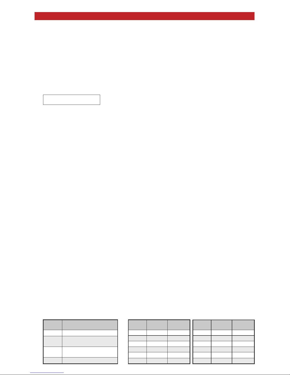
1. When the reader is powered up a victory beep (4-quick beeps) is heard and then the LED stays Red.
2. Present the correct card and the reader will beep once and LED will flash on and off. It is up to the control panel to control dual LED and
have the LED turn green when an enrolled card is presented.
3. If reader does not recognize the card/tag (no beep, no LED flash) or reader has short read range, please see table below for possible
causes and solutions:
If any of the corrective actions mentioned above don’t work, please disconnect the reader from panel and power it with a separate power supply
or 9V battery and test card functionality. By powering it individually and off the installation most variables that can cause malfunction are
eliminated. If after the reader is powered by a separate power source the failure persist, please contact Viking Electronics Product Support.
IF YOU HAVE A PROBLEM WITH A VIKING PRODUCT, CONTACT: VIKING TECHNICAL SUPPORT AT (715) 386-8666
Our Technical Support Department is available for assistance Monday through Friday 8:00am - 5:00pm central time. So that we can give you better service, before you call please:
1. Know the model number, the serial number and what software version you have (see serial label).
2. Have your Product Manual in front of you.
3. It is best if you are on site.
RETURNING PRODUCT FOR REPAIR
The following procedure is for equipment that needs repair:
1. Customer must contact Viking's Technical Support Department at 715-386-8666 to obtain a Return Authorization (RA) number. The customer MUST have a complete description of the problem,
with all pertinent information regarding the defect, such as options set, conditions, symptoms, methods to duplicate problem, frequency of failure, etc.
2. Packing: Return equipment in original box or in proper packing so that damage will not occur while in transit. Static sensitive equipment such as a circuit board should be in an anti-static bag,
sandwiched between foam and individually boxed. All equipment should be wrapped to avoid packing material lodging in or sticking to the equipment. Include ALL parts of the equipment. C.O.D. or
freight collect shipments cannot be accepted. Ship cartons prepaid to: Viking Electronics, 1531 Industrial Street, Hudson, WI 54016
3. Return shipping address: Be sure to include your return shipping address inside the box. We cannot ship to a PO Box.
4. RA number on carton: In large printing, write the R.A. number on the outside of each carton being returned.
RETURNING PRODUCT FOR EXCHANGE
The following procedure is for equipment that has failed out-of-box (within 10 days of purchase):
1. Customer must contact Viking’s Technical Support at 715-386-8666 to determine possible causes for the problem. The customer MUST be able to step through recommended tests for diagnosis.
2. If the Technical Support Product Specialist determines that the equipment is defective based on the customer's input and troubleshooting, a Return Authorization (R.A.) number will be issued.
This number is valid for fourteen (14) calendar days from the date of issue.
3. After obtaining the R.A. number, return the approved equipment to your distributor, referencing the R.A. number. Your distributor will then replace the Viking product using the same R.A. number.
4. The distributor will NOT exchange this product without first obtaining the R.A. number from you. If you haven't followed the steps listed in 1, 2 and 3, be aware that you will have to
pay a restocking charge.
Troubleshooting
TWO YEAR LIMITED WARRANTY
Viking warrants its products to be free from defects in the workmanship or materials, under normal use and service, for a period of two years from the date of purchase from
any authorized Viking distributor. If at any time during the warranty period, the product is deemed defective or malfunctions, return the product to Viking Electronics, Inc., 1531
Industrial Street, Hudson, WI., 54016. Customer must contact Viking's Technical Support Department at 715-386-8666 to obtain a Return Authorization (R.A.) number.
This warranty does not cover any damage to the product due to lightning, over voltage, under voltage, accident, misuse, abuse, negligence or any damage caused by use of
the product by the purchaser or others. This warranty does not cover non-EWP products that have been exposed to wet or corrosive environments. This warranty does not cover
stainless steel surfaces that have not been properly maintained.
NO OTHER WARRANTIES. VIKING MAKES NO WARRANTIES RELATING TO ITS PRODUCTS OTHER THAN AS DESCRIBED ABOVE AND DISCLAIMS ANY EXPRESS
OR IMPLIED WARRANTIES OR MERCHANTABILITY OR FITNESS FOR ANY PARTICULAR PURPOSE.
EXCLUSION OF CONSEQUENTIAL DAMAGES. VIKING SHALL NOT, UNDER ANY CIRCUMSTANCES, BE LIABLE TO PURCHASER, OR ANY OTHER PARTY, FOR
CONSEQUENTIAL, INCIDENTAL, SPECIAL OR EXEMPLARY DAMAGES ARISING OUT OF OR RELATED TO THE SALE OR USE OF THE PRODUCT SOLD HEREUNDER.
EXCLUSIVE REMEDY AND LIMITATION OF LIABILITY. WHETHER IN AN ACTION BASED ON CONTRACT, TORT (INCLUDING NEGLIGENCE OR STRICT LIABILITY) OR
ANY OTHER LEGAL THEORY, ANY LIABILITY OF VIKING SHALL BE LIMITED TO REPAIR OR REPLACEMENT OF THE PRODUCT, OR AT VIKING'S OPTION, REFUND OF
THE PURCHASE PRICE AS THE EXCLUSIVE REMEDY AND ANY LIABILITY OF VIKING SHALL BE SO LIMITED.
IT IS EXPRESSLY UNDERSTOOD AND AGREED THAT EACH AND EVERY PROVISION OF THIS AGREEMENT WHICH PROVIDES FOR DISCLAIMER OF WARRANTIES,
EXCLUSION OF CONSEQUENTIAL DAMAGES, AND EXCLUSIVE REMEDY AND LIMITATION OF LIABILITY, ARE SEVERABLE FROM ANY OTHER PROVISION AND EACH
PROVISION IS A SEPARABLE AND INDEPENDENT ELEMENT OF RISK ALLOCATION AND IS INTENDED TO BE ENFORCED AS SUCH.
PART 15 LIMITATIONS
This equipment has been tested and found to comply with the limits for a Class A digital device, pursuant to Part 15 of the FCC Rules. These limits are designed to provide
reasonable protection against harmful interference when the equipment is operated in a commercial environment. This equipment generates, uses, and can radiate radio
frequency energy and, if not installed and used in accordance with the instruction manual, may cause harmful interference to radio communications. Operation of this
equipment in a residential area is likely to cause harmful interference in which case the user will be required to correct the interference at his own expense.
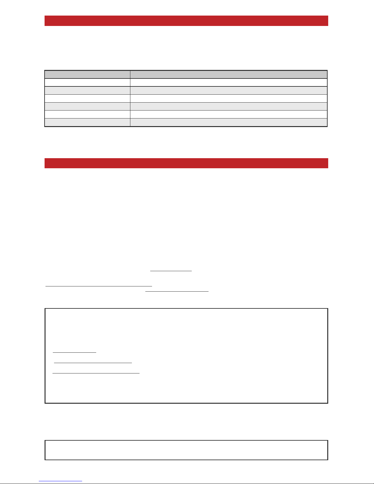
Possible Cause Corrective Action
Incorrect wiring Verify wiring connection
Not enough power 12 VDC suggested
Mounted near electromagnetic interference Relocate or provide greater separation from
Incorrect card used Verify card compatibility from model number
Reader/access panel not properly grounded Quality Earth Ground needed. Verify shield line from access panel to reader is one continuous, connected line.
Supply generating electromagnetic interference Linear power supply recommended

Other Viking Card Reader manuals

Viking PRX-5 User manual

Viking

Viking PRX-5 User manual

Viking PROX-3 User manual

Viking

Viking PROX-3 User manual

Viking PRX-1 User manual

Viking

Viking PRX-1 User manual

Viking PROX-1 Instructions for use

Viking

Viking PROX-1 Instructions for use

Viking 1005294 User manual

Viking

Viking 1005294 User manual

Popular Card Reader manuals by other brands

Decagon Devices ProCheck Operator's manual

Decagon Devices

Decagon Devices ProCheck Operator's manual

SanDisk SDDR-92-A15 - ImageMate USB 2.0 Reader/Writer Card... user guide

SanDisk

SanDisk SDDR-92-A15 - ImageMate USB 2.0 Reader/Writer Card... user guide

Atech Flash Technology PRO-35U user guide

Atech Flash Technology

Atech Flash Technology PRO-35U user guide

Icy Box IB-867 Technical data

Icy Box

Icy Box IB-867 Technical data

Salto WRLUD24B series user manual

Salto

Salto WRLUD24B series user manual

Kobil SecOVID Reader III manual

Kobil

Kobil SecOVID Reader III manual

StarTech.com FCREADHC instruction manual

StarTech.com

StarTech.com FCREADHC instruction manual

DoorKing 1815-247 manual

DoorKing

DoorKing 1815-247 manual

Iseo Zero1 Stylos 2 installation guide

Iseo

Iseo Zero1 Stylos 2 installation guide

Sony MRW620-U1 operating instructions

Sony

Sony MRW620-U1 operating instructions

AWID MPR-5005 Installation & operation manual

AWID

AWID MPR-5005 Installation & operation manual

Roger PRT12EM operating manual

Roger

Roger PRT12EM operating manual

Saxxon FC06 user manual

Saxxon

Saxxon FC06 user manual

3MillID Inline Reader manual

3MillID

3MillID Inline Reader manual

ECS UCR-61S2B Quick installation guide

ECS

ECS UCR-61S2B Quick installation guide

Conrad Akasa Baymaster AK-ICR-10 operating instructions

Conrad

Conrad Akasa Baymaster AK-ICR-10 operating instructions

Datalogic DLC6100 Series quick reference

Datalogic

Datalogic DLC6100 Series quick reference

Posi Pin CR-R885-SB Installation and operating instructions

Posi Pin

Posi Pin CR-R885-SB Installation and operating instructions

manuals.online logo
manuals.online logoBrands
  • About & Mission
  • Contact us
  • Privacy Policy
  • Terms and Conditions

Copyright 2025 Manuals.Online. All Rights Reserved.