Viking C-3000 Instructions for use

This entry system is designed to utilize a building’s existing
telephone wiring and to address a variety of apartment entry
applications. Viking’s C-3000 Entry System provides secure
multi-tenant building access, without the need for any C.O.
lines; the only requirement is that each tenant have a touch-
tone telephone set wired to their apartment. The C-3000 per-
forms equally as well in installations where C.O. lines are
present. An individual C-3000 module has a 12-tenant capac-
ity; for larger applications, a maximum of eight (8) C-3000
modules can be interconnected, allowing a total system
capacity of up to 96 tenants. A C-3000 system consists of at
least one Master C-3000 module, and as many as seven
Slave modules.
Add Apartment Entry Without Rewiring
P
Ph
ho
on
ne
e.
..
..
.7
71
15
5.
.3
38
86
6.
.8
88
86
61
1
h
ht
tt
tp
p:
:/
//
/w
ww
ww
w.
.v
vi
ik
ki
in
ng
ge
el
le
ec
ct
tr
ro
on
ni
ic
cs
s.
.c
co
om
m
• Utilizes building’s existing telephone wiring, yet
functions with or without tenant CO lines
• No monthly charges for a dedicated line
• Tenants do not require phone service
• Programmable keyless entry code for each tenant
• Distinctive ring cadence and call waiting
• Programmable from dedicated programming
phone
• Supports (2) entry doors and (2) door strikes
• 12-tenant capacity may be expanded to 96 ten-
ants at any time
• Compatible with Viking’s vandal resistant
K-1700-3, K-1900-8 or any Touch Tone phone
• May be wired so that tenants may talk to visitors
without disrupting C.O. modem transmissions
• Allows visitors to leave voice messages on ten-
ants personal answering machines
Power: 120VAC / 13.8VAC 1.25A, UL listed adapter provided
Dimensions: 211mm x 160mm x 46mm (8.30" x 6.30" x 1.80")
Shipping weight: 1.0kg (2.2 lbs.)
Environmental: 0° C to 32° C (32° F to 90° F) with 5% to 95%
non-condensing humidity
Talk battery: 40VDC
Relay contact ratings: 5A @ 30VDC / 250VAC
Maximum System Door Phones/Door Strikes: (2) each
Maximum System Tenant Capacity: 96 - using (8) C-3000
modules
Ring Generator: 90V AC nominal, 7 REN maximum
Connections: (1) RJ-21X female 25-pair, (3) RJ-11 female, (13)
terminal block positions
P
Pr
ra
ac
ct
ti
ic
ce
e
T
TE
EL
LE
EC
CO
OM
MS
SO
OL
LU
UT
TI
IO
ON
NS
SF
FO
OR
RT
TH
HE
E2
21
1S
ST
TC
CE
EN
NT
TU
UR
RY
Y
TECHNICAL
TECHNICAL
F
Fe
ea
at
tu
ur
re
es
s
S
Sp
pe
ec
ci
if
fi
ic
ca
at
ti
io
on
ns
s
From either of two entry doors, visitors may ring a tenant's telephone with a distinctive cadence, alerting
the tenant of their arrival. The C-3000 provides call waiting tones if the tenant’s line is in use. The tenant
may then converse freely with the visitor via their existing telephones. Once identified, the tenant can let
the visitor in by entering a single touch-tone on the keypad of the tenant's telephone set.
The C-3000 keyless entry feature supports unique entry codes for each tenant. As a measure of securi-
• Apartments and condominiums
• Buildings where some or all tenants lack phone
service
• Supervised living
• Student housing
• Retrofit older construction
A
Ap
pp
pl
li
ic
ca
at
ti
io
on
ns
s
i
in
nf
fo
o@
@v
vi
ik
ki
in
ng
ge
el
le
ec
ct
tr
ro
on
ni
ic
cs
s.
.c
co
om
m
ty, the codes can be easily changed as
tenants move in and out of the building.
A postal lock feature is also supplied as
an added convenience.
C-3000
C-3000
Apartment Entry
System
May 12, 2006

Module 1
“Master”
1
2
3
4
5
6
7
8
9
10
11
12
1
2
3
4
5
6
7
8
9
10
11
12
I
In
ns
st
ta
al
ll
la
at
ti
io
on
n
A. Definitions
Master Module: The C-3000 module assigned module ID #1. Also, the only module in a single-module system.
Slave Module(s): Any module(s) in addition to the Master, in a multi-module C-3000 system. Slave modules are
assigned module ID numbers in the range of #2 through #8.
“66” Punchdown Terminal Block: A connection peripheral used to interface telephone lines easily. This installation
requires a “split” punchdown block.
B. Preparing the Installation
Select an appropriate location in which to install the C-3000 System. It is normally most convenient to install the C-3000
modules as near as possible to the telco demarcation point; that is, the common point at which all tenant phone lines
enter the building (if applicable). If the tenant phone wiring is not currently cabled though a "66" block or blocks, it will
be necessary to install "66" block(s) at this time to facilitate the installation of the C-3000 system. Note: See the instal-
lation diagram on the following page for recommendations on which “66” block to use.
C. Assigning Module ID Numbers
AC-3000 system consists of at least one (Master) C-3000 module, and as many as seven (7) Slave modules. Multiple
C-3000 modules are all interconnected from module to module, using the supplied modular cords, connecting the
MULTI-MODULE INTERCONNECTS from IN to OUT. If more than one C-3000 module is being installed, it will be nec-
essary to set module ID numbers at this time. Each C-3000 module must have it's own ID number to be part of a C-
3000 system. Module ID numbers are set using the three-position DIP switches on the front of the C-3000 modules
(see diagram below). Module ID numbers are used to determine which C-3000 module is responsible for handling a
particular range of apartment numbers. As an example, Module #1 (the Master module) handles apartment numbers 1-
12, Module #2 handles apartment numbers 13-24 and so forth.
D. Wiring Table
Refer to the wiring table below when installing the cabling for the C-3000 system. Note that tenant line 1 enters on pins
1 & 26 of the RJ-21X connector, and exits on pins 2 & 27 of the same connector. This also means a visitor would dial
a touch tone 1 to call the tenant connected to line 1. This scheme is used on all 12 lines on the RJ-21X connector,
occupying all pins up thorough the pin 24 & 49 pair, and repeats on up to the 96th tenant on the
8th module. The last pair on the RJ-21X connector (pins 25 & 50) has a special function. This
last pair is used (on the Master module only) as a connection for the Building Manager's
Programming Phone.
Module ID
Assignment Module 2
“Slave”
13
14
15
16
17
18
19
20
21
22
23
24
13
14
15
16
17
18
19
20
21
22
23
24
n/a
Module 3
“Slave”
25
26
27
28
29
30
31
32
33
34
35
36
25
26
27
28
29
30
31
32
33
34
35
36
n/a
Module 4
“Slave”
37
38
39
40
41
42
43
44
45
46
47
48
37
38
39
40
41
42
43
44
45
46
47
48
n/a
Module 5
“Slave”
49
50
51
52
53
54
55
56
57
58
59
60
49
50
51
52
53
54
55
56
57
58
59
60
n/a
Module 6
“Slave”
61
62
63
64
65
66
67
68
69
70
71
72
61
62
63
64
65
66
67
68
69
70
71
72
n/a
Module 7
“Slave”
73
74
75
76
77
78
79
80
81
82
83
84
73
74
75
76
77
78
79
80
81
82
83
84
n/a
Module 8
“Slave”
85
86
87
88
89
90
91
92
93
94
95
96
85
86
87
88
89
90
91
92
93
94
95
96
n/a
ON
OFF 123
ON
OFF 123
ON
OFF 123
ON
OFF 123
ON
OFF 123
ON
OFF 123
ON
OFF 123
ON
OFF 123
DIP Switch
Settings
C.O.
Lines In
Lines Out
to
Apartment
Phones
(Dial Up
Codes)
Tip
26 W/BL
28 W/G
30 W/S
32 R/O
34 R/BN
36 BK/BL
38 BK/G
40 BK/S
42 Y/O
44 Y/BN
46 V/BL
48 V/G
27 W/O
29 W/BN
31 R/BL
33 R/G
35 R/S
37 BK/O
39 BK/BN
41 Y/BL
43 Y/G
45 Y/S
47 V/O
49 V/BN
50 V/S
Ring
1 BL/W
3 G/W
5 S/W
7 O/R
9 BN/R
11 BL/BK
13 G/BK
15 S/BK
17 O/Y
19 BN/Y
21 BL/V
23 G/V
2 O/W
4 BN/W
6 BL/R
8 G/R
10 S/R
12 O/BK
14 BN/BK
16 BL/Y
18 G/Y
20 S/Y
22 O/V
24 BN/V
25 S/V
Bldg Mgr Phn
VIKING©MODEL C-3000
VIKING
ELECTRONICS
HUDSON, WI 54016
12 UNIT APARTMENT
ENTRY CONTROLLER MODULE
POWER
13.8 VAC
3456712
DOOR
STRIKE
1
DOOR
STRIKE
2
DIP
SWITCH
1 2 3
RJ21X
12 APARTMENT LINES IN/OUT
8
ENTRY
PHONE 1
MULTI-MODULE
INTERCONNECTS
POSTAL
LOCK
INPUT
ENTRY
PHONE 2 OUT IN
PWR
IN
USE
PROGRAMPHONE
O
N
O
F
F
RJ-21X
2

VIKING©
MODEL C-3000
VIKING
ELECTRONICS
HUDSON, WI 54016
12 UNIT APARTMENT
ENTRY CONTROLLER MODULE
POWER
13.8 VAC
3456712
DOOR
STRIKE
1
DOOR
STRIKE
2
DIP
SWITCH
1 2 3
RJ21X
12 APARTMENT LINES IN/OUT
8
ENTRY
PHONE 1
MULTI-MODULE
INTERCONNECTS
POSTAL
LOCK
INPUT
ENTRY
PHONE 2 OUT IN
PWR
IN
USE
PROGRAM PHONE
O
N
O
F
F
* Earth
Ground
(optional)
Row 1
C.O. Lines
1T
1R
2T
2R
3T
3R
4T
4R
5T
5R
6T
6R
7T
7R
8T
8R
9T
9R
10T
10R
11T
11R
12T
12R
Row 2
C-3000
26 W/BL
1 BL/W
28 W/G
3 G/W
30 W/S
5 S/W
32 R/O
7 O/R
34 R/BN
9 BN/R
36 BK/BL
11 BL/BK
38 BK/G
13 G/BK
40 BK/S
15 S/BK
42 Y/O
17 O/Y
44 Y/BN
19 BN/Y
46 V/BL
21 BL/V
48 V/G
23 G/V
Row 3
C-3000
27 W/O
2 O/W
29 W/BN
4 BN/W
31 R/BL
6 BL/R
33 R/G
8 G/R
35 R/S
10 S/R
37 BK/O
12 O/BK
39 BK/BN
14 BN/BK
41 Y/BL
16 BL/Y
43 Y/G
18 G/Y
45 Y/S
20 S/Y
47 V/O
22 O/V
49 V/BN
24 BN/V
50 V/S
25 S/V
Add up to 6 more C-3000
Control Modules for a
total of 96 apartments.
Module ID #2
“Slave” for Apts 13-24
Module ID #1
“Master” for
Apts 1-12
ON
OFF 123
ON
OFF 123
Bridged Bridged
Programming
Phone
Row 1
C.O. Lines
13T
13R
14T
14R
15T
15R
16T
16R
17T
17R
18T
18R
19T
19R
20T
20R
21T
21R
22T
22R
23T
23R
24T
24R
Row 2
C-3000
26 W/BL
1 BL/W
28 W/G
3 G/W
30 W/S
5 S/W
32 R/O
7 O/R
34 R/BN
9 BN/R
36 BK/BL
11 BL/BK
38 BK/G
13 G/BK
40 BK/S
15 S/BK
42 Y/O
17 O/Y
44 Y/BN
19 BN/Y
46 V/BL
21 BL/V
48 V/G
23 G/V
Row 3
C-3000
27 W/O
2 O/W
29 W/BN
4 BN/W
31 R/BL
6 BL/R
33 R/G
8 G/R
35 R/S
10 S/R
37 BK/O
12 O/BK
39 BK/BN
14 BN/BK
41 Y/BL
16 BL/Y
43 Y/G
18 G/Y
45 Y/S
20 S/Y
47 V/O
22 O/V
49 V/BN
24 BN/V
Bridged Bridged
Front Door Entry
Phone 1
Rear Door Entry
Phone 2
Row 4
Apt Phns
1T
1R
2T
2R
3T
3R
4T
4R
5T
5R
6T
6R
7T
7R
8T
8R
9T
9R
10T
10R
11T
11R
12T
12R
T
R
12 C.O.
Lines In
Building Manager’s
Programming Phone
To Apartment
Phones 1-12
Example: Type 66
Punchdown Terminal
Block with Split Center
(not included)
Row 4
Apt Phns
13T
13R
14T
14R
15T
15R
16T
16R
17T
17R
18T
18R
19T
19R
20T
20R
21T
21R
22T
22R
23T
23R
24T
24R
12 C.O.
Lines In
To Apartment
Phones 13-24
Set DIP switches using the wiring
table on the previous page to
assign the module ID numbers.
Postal Lock
Input
(not included)
K-1700-3 shown
(not included)
Fax Back # 157
E. Standard Wiring
Important: Interconnect all modules coming OUT of the last slave module IN
to the next, continuing from module to module on up to the Master module
using the supplied standard modular cords. After wiring is complete, power up
the last slave module first, continuing forward to the master module.
13.8V AC
Adapter
(included)
Standard
Modular Cord
Note: If the Master C-3000 is powered up first, it is
normal for the power LED’s of all C-3000’s to light.
3
* Note: To increase
surge protection, fasten
a wire from the screw
terminal to Earth Ground
(grounding rod, water
pipe, etc.)
(The polarity
of this modu-
lar cord must
be correct.
See probable
cause and
solution for
symptom 2
on page 8 for
details.)

L1 L2 L1/L2
Y/BK Pair
R/G Pair
12 C.O.
Lines In
To Modem
RJ-14 Jack
in Apartments
R/G = Phones
Y/BK = Modem
Radio Shack Line Splitter
Model #279-402 or #279-432
Punchdown Terminal
Block with Split Cente
r
(not included)
Siemans # 566B3-50
Marconi # R66B3-50
VIKING©MODEL C-3000
VIKING
ELECTRONICS
HUDSON, WI 54016
12 UNIT APARTMENT
ENTRY CONTROLLER MODULE
POWER
13.8 VAC
3456712
DOOR
STRIKE
1
DOOR
STRIKE
2
DIP
SWITCH
1 2 3
RJ21X
12 APARTMENT LINES IN/OUT
8
ENTRY
PHONE 1
MULTI-MODULE
INTERCONNECTS
POSTAL
LOCK
INPUT
ENTRY
PHONE 2 OUT IN
PWR
IN
USE
PROGRAM PHONE
O
N
O
F
F
DSL Filter
F. Wiring with Modems (including DSL Lines)
The C-3000 may be wired with this alternate wiring scheme which allows tenants to talk to their visitors without dis-
rupting their C.O. modem transmissions, or losing DSL carrier signals. It requires two pair runs and RJ-14 jacks for
each apartment. In this scheme, the modem will be connected to the Y/BK pair of the RJ-14 which is wired ahead of
the C-3000, directly to the C.O. line. Use a 2 line splitter to connect the modem to the Y/BK pair. Wiring in this manor
for all apartments assures a smooth transition as tenants add modems and DSL service in the future.
Bridged Bridged
Row 6
Apt Phns
1G
1R
2G
2R
3G
3R
4G
4R
5G
5R
6G
6R
7G
7R
8G
8R
9G
9R
10G
10R
11G
11R
12G
12R
Row 4
Not Used
N/C
N/C
N/C
N/C
N/C
N/C
N/C
N/C
N/C
N/C
N/C
N/C
N/C
N/C
N/C
N/C
N/C
N/C
N/C
N/C
N/C
N/C
N/C
N/C
Row 5
C-3000
27 W/O
2 O/W
29 W/BN
4 BN/W
31 R/BL
6 BL/R
33 R/G
8 G/R
35 R/S
10 S/R
37 BK/O
12 O/BK
39 BK/BN
14 BN/BK
41 Y/BL
16 BL/Y
43 Y/G
18 G/Y
45 Y/S
20 S/Y
47 V/O
22 O/V
49 V/BN
24 BN/V
Row 1
C.O. Lines
1T
1R
2T
2R
3T
3R
4T
4R
5T
5R
6T
6R
7T
7R
8T
8R
9T
9R
10T
10R
11T
11R
12T
12R
Row 2
C-3000
26 W/BL
1 BL/W
28 W/G
3 G/W
30 W/S
5 S/W
32 R/O
7 O/R
34 R/BN
9 BN/R
36 BK/BL
11 BL/BK
38 BK/G
13 G/BK
40 BK/S
15 S/BK
42 Y/O
17 O/Y
44 Y/BN
19 BN/Y
46 V/BL
21 BL/V
48 V/G
23 G/V
Row 3
Apt Modem
1BK
1Y
2BK
2Y
3BK
3Y
4BK
4Y
5BK
5Y
6BK
6Y
7BK
7Y
8BK
8Y
9BK
9Y
10BK
10Y
11BK
11Y
12BK
12Y
C.O. Line
Phone
OutIn
Modem or
DSL Modem
R/G
Y/BK
VIKING©MODEL C-3000
VIKING
ELECTRONICS
HUDSON, WI 54016
12 UNIT APARTMENT
ENTRY CONTROLLER MODULE
POWER
13.8 VAC
3456712
DOOR
STRIKE
1
DOOR
STRIKE
2
DIP
SWITCH
1 2 3
RJ21X
12 APARTMENT LINES IN/OUT
8
ENTRY
PHONE 1
MULTI-MODULE
INTERCONNECTS
POSTAL
LOCK
INPUT
ENTRY
PHONE 2 OUT IN
PWR
IN
USE
PROGRAM PHONE
O
N
O
F
F
DSL Filter
1. Concept
2. Detailed Example
4

VIKING©MODEL C-3000
VIKING
ELECTRONICS
HUDSON, WI 54016
12 UNIT APARTMENT
ENTRY CONTROLLER MODULE
POWER
13.8 VAC
3456712
DOOR
STRIKE
1
DOOR
STRIKE
2
DIP
SWITCH
1 2 3
RJ21X
12 APARTMENT LINES IN/OUT
8
ENTRY
PHONE 1
MULTI-MODULE
INTERCONNECTS
POSTAL
LOCK
INPUT
ENTRY
PHONE 2 OUT IN
PWR
IN
USE
PROGRAM PHONE
O
N
O
F
F
5A @ 30V DC
maximum
(not included)
13.8V AC
Adapter
(included)
* Doorstrike
Power Supply
Doorstrike
Door 5A @ 30V DC
maximum
(not included)
* Magnetic Lock
Power Supply
Magnetic Lock
Door
G. Door Strike Relay Wiring
Use the relay contacts of the Master module to activate door strikes, magnetic locks, and gate controls. Normally
closed, normally open and common contacts are provided for both entry locations.
* Note: Gate controllers do
not typically require power.
Doorstrike 1
3
4
5
Normally Open
Common
Normally Closed
Doorstrike 2
6
7
8
Normally Open
Common
Normally Closed
P
Pr
ro
og
gr
ra
am
mm
mi
in
ng
g
A. Definitions
Program Phone: A single line telephone or buttset connected to the Program Phone port (RJ-11) of a C-3000 module.
Building Manager's Programming Phone: A single line telephone or buttset connected to pins 25/50 so that the Building Manger
may easily change keyless entry codes, without the necessity of travelling to the C-3000 system.
Tenant Keyless Entry code: A four to six-digit code assigned to a tenant, which is used to gain access to the building through the
C-3000 system. Keyless entry codes are programmed into memory positions #01-#96. There are no factory default settings for these
values, nor is it a requirement that they be set.
Master Keyless Entry Code: A single four to six-digit code, which is normally not assigned to a tenant, but may be made known to
the building manager, maintenance or security personnel. The Master keyless entry code is programmed into memory position #00.
There is no factory default setting for this value, nor is there a requirement that it be set.
Relay Activation Time: The period of time (in seconds) for which a C-3000 door strike relay will remain activated, after having been
given an activation code. This value is factory preset to (5) seconds.
Relay Activation Code: The one-digit code entered on a tenant's touch-tone telephone keypad, which will activate a door strike
relay to allow a visitor access to the building. This code is factory preset to "6".
Maximum Call Time: The maximum time (in minutes) allowed for a single conversation between a visitor at the door phone and a
tenant. If this time is exceeded, both parties will be disconnected. This value is factory preset to (2) minutes.
Maximum Ring Count: The maximum number of times the C-3000 system will ring any tenant's telephone, after being activated by
a visitor at the door phone. This value is factory preset to (7) rings.
Number of Modules: The sum total of C-3000 modules in the C-3000 system. This value is factory preset to (1).
B. Quick Programming Guide
Master Module Set Up
Number of modules (1-8, factory set to 1) ...................................................................
Master keyless entry code (4-6 digits, no digits disables) ............................................
Tenants keyless entry codes (4-6 digits, no digits disables) ........................................
Clear all keyless entry codes and set all programming features to factory settings .....
Slave and Master Module Set Up
Relay activation time (0-9, factory set to 5 sec, 0=.5 sec) ............................................
Relay activation code (factory set to 6) (cannot be a # or a 4) (no digit=disable) .........
Maximum entry phone time (0-9, factory set to 2 min, 0=disabled) .............................
Maximum ring count (0-9, factory set to 7, 0=10) .......................................................
Enter Digits
1 digit
4-6 digits
4-6 digits
1 digit
1 digit
1 digit
1 digit
- then -
+
+
+
+
+
+
+
Memory
Location
##8
#00
#01 - #96
###
##3
##4
##6
##7 5

4. Maximum Ring Count (1-10 rings: factory default = 7 rings)
(1digit, 0-9) + ##7 ("0"= 10 rings) Example: o set the Maximum Ring Count to 8, come off-hook with the Program
Phone and enter "8##7". Two beeps will confirm a valid entry, three beeps will signify an error. Repeat this proce-
dure for each module.
3. Maximum Entry Phone Time (1-9 minutes: factory default = 2 minutes)
(1digit, 0-9) + ##6 ("0"=disabled) Example: To set the Maximum Entry Phone time limit to 3 minutes, come off-
hook with the Program Phone and enter "3##6". Entering "0##6" or just “##6” will disable the time limit. Two beeps
will confirm a valid entry, three beeps will signify an error. Repeat this procedure for each module.
2. Relay Activation Code (factory default = 6)
(1digit, 0-9) + ##4 Example: To set the door strike relay to activate with the code "0", come off-hook with the
Program Phone and enter "0##4". Two beeps will confirm a valid entry, three beeps will signify an error. Repeat this
procedure for each module.
C. Master C-3000 Module Setup
The following setup procedures are performed only on the Master module (ID #1) in the C-3000 system. Come off-hook
with the Program Phone on the Master module, and program the following settings.
4. Clear All Keyless Entry Code Positions and Set Programming Features to Default (optional)
### Example: To clear all Keyless Entry code positions in the entire C-3000 system and return all programming
settings back to factory default, enter "###". Two beeps will confirm a valid entry, three beeps will signify an error.
Note: Be EXTREMELY careful with the use of this feature, as it will immediately erase ALL keyless entry codes in
the system, with no possibility for recovery. It is suggested that this feature be exercised when installing a new C-
3000 system, before any other programming is performed.
2. Set Master Keyless Entry Code (optional)
(4-6 digits, 0-9) + #00 -or- #00 alone to clear this position Example: To set the Master Keyless entry code to
"052069" you would come off-hook with the Program Phone and enter "052069#00.” Entering "#00" without any
leading digits will clear this position. Two beeps will confirm a valid entry, three beeps will signify an error.
Note: The entry codes should all be the same number of digits, either 4, 5 or 6.
3. Set Tenant Keyless Entry Codes (optional)
(4-6 digits, 0-9) + #01-#96 -or- #01-#96 alone to clear that position Example: To set the Tenant Keyless Entry code
for apartment "24" to "052069" you would come off-hook with the Program Phone and enter "052069#24.” Entering
"#01" through "#96" without any leading digits will clear the respective position. Two beeps will confirm a valid entry,
three beeps will signify an error. Note that there are 96 tenant keyless entry codes available regardless of how many
C-3000’s have been installed. For example, in an installation with just one C-3000, the first 12 keyless entry codes
corresponding to memory positions #01-#12 can each be individually assigned to one of the 12 apartments.
However, the remaining 84 keyless codes corresponding to memory position #13-#96 are still available and will be
functional if programmed, allowing for more than one keyless entry code per apartment or keyless codes specifically
assigned for maintenance personnel. It is important to carefully document any codes that are programmed so that
they can be cleared if required. Note: The entry codes should all be the same number of digits, either 4, 5 or 6.
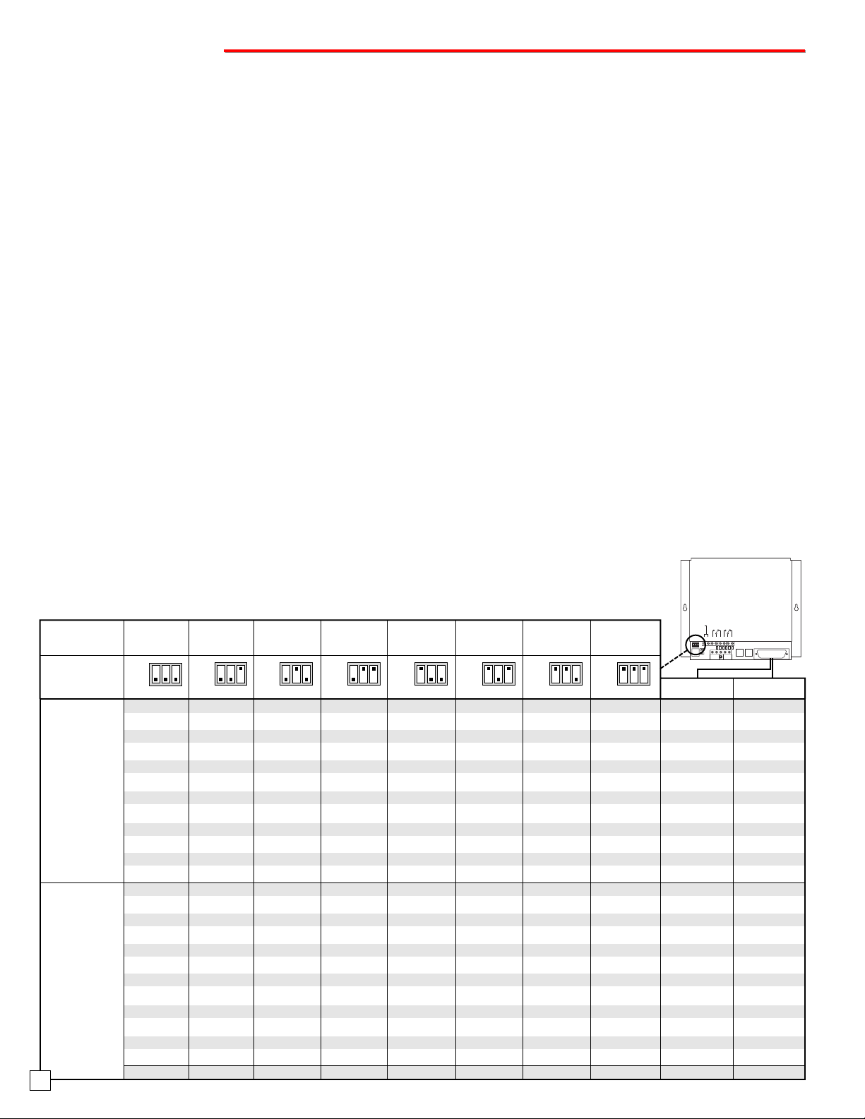
1. Set Number of Modules
(1digit, 1-8) + ##8 Example: If the C-3000 system will consist of (4) modules, you would come off hook with the
programming phone and enter "4##8.” Two beeps will confirm a valid entry, three beeps will signify an error. This
value is factory preset to (1).
D. General C-3000 System Setup
The following procedures are to be performed on each module in the C-3000 system, one module at a time. Note that
while each module needs to be programmed separately, it is standard practice to make all of the following settings iden-
tical, for all modules. All four system setup programmable features are pre-programmed to factory defaults. If these
settings are acceptable, then there is no need for additional programming.
1. Relay Activation Time (.5 - 9 seconds: factory default = 5 seconds)
(1digit, 0-9) + ##3 ("1"=1 second, "0"=.5 second) Example: To set the door strike relay to activate for 8 seconds,
you would come off-hook on the Program Phone and enter "8##3". Two beeps will confirm a valid entry, three beeps
will signify an error. Repeat this process for each module.
6

M
Ma
as
st
te
er
r/
/S
Sl
la
av
ve
eT
Tr
ro
ou
ub
bl
le
es
sh
ho
oo
ot
ti
in
ng
gG
Gu
ui
id
de
e
Symptom 1:
The entry phone is able to call a slave apartment, but when they attempt to dial the relay command ("6" by default), the
door/gate doesn't open (the doorstrike contacts of the master C-3000 don't operate). When calling a master apartment and
dialing the relay command, the door/gate does open. Also, the doorstrike contacts of the slave C-3000 are activating when
the entry phone calls a slave apartment and the party dials the relay command (the slave C-3000's relay would not activate
in a working master/slave configuration).
Probable Cause and Solution:
Check the "multi-module interconnect" modular cord between the master and slave (or in larger "stacks", the cord between
the first slave C-3000 with the problem and the slave C-3000 ahead of it in the stack). If the cord is only a two conductor
modular cord, it must be replaced with a four conductor modular cord. If it is a four conductor modular cord, the cord has
an open in the second pair (yellow or black wires) and should be replaced (the polarity of this modular cord must be cor-
rect - see Probable Cause and Solution for symptom 2).
O
Op
pe
er
ra
at
ti
io
on
n
A. Receiving a Visitor
A visitor arrives, takes the entry phone off-hook and dials a one or two-digit code (1-96), which corresponds to an indi-
vidual tenant's apartment (see Wiring Table in Installation section D). The telephone(s) in the tenant's apartment then
begin to ring in a special "double-ring" cadence, notifying the tenant that they have a visitor at the door. The tenant may
then answer the call from any phone, and converse normally with the visitor. If the tenant's phone is already in use, the
tenant receives a "call waiting" type tone, notifying them of the visitor's call. A hookswitch flash from the tenant's phone
will put the current call on hold, and answer the visitor's call. A second hookswitch flash from the tenant's phone will
disconnect the visitor's call and return the tenant to the original call, without allowing the visitor access to the building.
Note that when either of the two entry phones are in use, the other entry phone is disabled for the duration of the call.
B. Allowing a Visitor Entry
After communicating with a visitor at the door, the tenant can allow the visitor access to the building by entering a pro-
grammable code on the tenant's touch-tone telephone. The factory default relay activation code is "6". Upon entering
this code, both parties will hear a brief buzzing tone as they are disconnected from the telephones, and the door strike
relay operates giving the visitor access to the building. If the tenant had a call in progress, the tenant will also be auto-
matically returned to the original call. If the visitor attempts to enter the relay entry code themselves, the C-3000 sys-
tem detects this and automatically disconnects both parties, without activating the doorstrike relay.
C. Keyless Entry
Each tenant can be assigned a unique four to six-digit entry code, which may be used to gain access to the building
without their key. In addition to the 96 tenant Keyless Entry codes, there is also one additional "Master" keyless entry
code. To access the Keyless Entry feature, the tenant takes an entry phone off-hook and enters "#", plus their keyless
entry code. The doorstrike relay will then operate to allow the tenant access to the building. Note that it is not a require-
ment to set or use the C-3000 keyless entry feature.
D. Changing Keyless Entry Codes or Programming Features
From the Building Manager's Phone or the “Program Phone” port, all programming, including codes, can be performed.
To change a keyless entry code, the Building Manager picks up the Building Manager's Programming phone, (if both
entry phones are idle, two beeps will be heard to confirm that the C-3000 system is ready for programming) and dials:
(New 4-6 digit entry code) + "#" + (00-96)
For example, to set the Keyless Entry code for apartment 24 to "052069", the Building Manager would enter
"052069#24" and then hang up, unless additional codes need to be changed. Two more beeps from the Building
Manager's programming phone confirm a valid entry, three beeps will signify an error. See the "Programming" section
for full details on the procedure for changing keyless entry codes. Note: Both entry phones are disabled during pro-
gramming.
E. Postal Lock Feature (Authorized Persons Only)
This feature is provided to allow an authorized person, such as a Postal Service worker to gain access to the building
using a special key lock switch dedicated to this purpose. Keying the Postal Lock (momentary contact closure) will acti-
vate door strike 1 contacts for about 5 seconds.
7

Due to the dynamic nature of the product design, the information contained in this document is subject to change without notice. Viking Electronics, and its affiliates and/or
subsidiaries assume no responsibility for errors and omissions contained in this information. Revisions of this document or new editions of it may be issued to incorporate
such changes.
Fax Back Doc 162 ZF301510 Rev BPrinted in the U.S.A.
E
En
nt
tr
ry
yS
Sy
ys
st
te
em
mU
Us
se
er
rs
sG
Gu
ui
id
de
e
A. Receiving a Visitor
Upon arrival, a visitor dials the code ________ found on the directory of your apartment. Your telephone(s) then
begin to ring in a special double-ring cadence, notifying you that you have a visitor at the door. You may then
answer the call from any phone, and converse normally with the visitor. If your phone is already in use, you
receive a “call-waiting” type tone, notifying you of the visitors call. A hookswitch flash (a quick momentary hang-
up of your phone) will put the current call on hold, and answer the visitor’s call. A second hookswitch flash from
your phone will disconnect the visitor’s call and return you to the original call without allowing the visitor access
to the building.
B. Allowing a Visitor Entry
After communicating with a visitor at the door, you can allow the visitor access to the building by entering a
________ on your Touch Tone telephone. Upon entering this code, both parties will hear a brief buzzing tone
while the visitor is allowed access to the building. If you were on a call, you will be automatically returned to the
original call.
C. Keyless Entry
Each tenant can be assigned a unique four to six-digit entry code, which may be used to gain access to the
building without their key. To use the Keyless Entry feature, push the “Call” button or take the entry phone off-
hook and enter _______.
Note to Building Managers: Please make copies of this form, fill them out and distribute to your tenants.
Tenant Name: _________________________________ Tenant Unit #: ____________________________
Tenant Phone #: _______________________________
P
Pr
ro
od
du
uc
ct
tS
Su
up
pp
po
or
rt
tL
Li
in
ne
e.
..
..
.7
71
15
5.
.3
38
86
6.
.8
86
66
66
6F
Fa
ax
xB
Ba
ac
ck
kL
Li
in
ne
e.
..
..
.7
71
15
5.
.3
38
86
6.
.4
43
34
45
5
8
Symptom 2:
As soon as the "multi-module interconnect" modular cord is connected from the "in" of the master C-3000 to the "out" of the
slave C-3000, the "in-use" LED's light up steady on both C-3000's.
Probable Cause and Solution:
The modular cord being used to connect the C-3000's together is the wrong polarity. The modular cord must be a standard
"straight through" modular cord, rather than a "reversed" modular cord. The modular cord supplied with the C-3000 is the
correct polarity. Either use the supplied modular cord, or make sure the locking tab is on the same side of the modular cord
at both ends, if making your own modular cords.
Symptom 3:
Everything works properly when the entry phone calls an apartment on the master C-3000. When the entry phone tries to
call a slave apartment, the entry phone receives both ringback tones and a busy signal (at the same time), as the call is
ringing through to the slave apartment.
Probable Cause and Solution:
The master C-3000 has not been properly programmed with the "number of modules" in the stack (##8 memory location).
The master C-3000 must be told how many C-3000's are in the stack and this is set to one by default. Program the mas-
ter with the correct number of units in the stack. See Programming, Section C (Master Module Setup) for programming
details.
Other manuals for C-3000
1
Table of contents