Viking G-4000P Instruction manual

TECHNICAL DATA
May 28, 2013
4” MODEL G-4000P PREACTION
WITH ELECTRIC RELEASE
The Viking Corporation, 210 N Industrial Park Drive, Hastings MI 49058
Telephone: 269-945-9501 Technical Services: 877-384-5464 Fax: 269-818-1680 Email: techsvcs@vikingcorp.com
Preaction 325a
1. DESCRIPTION
The 4” Model G-4000P Electric Release Preaction System Riser Assembly can be used as a
Single Interlock Preaction System with Electric Release, or as a Double Interlock Preaction
System with Electric/Pneu-Lectric Release. These preaction systems are commonly usedThese preaction systems are commonly used
where it is important to control accidental water discharge due to inadvertent damage to the
sprinkler piping. The small profile, lightweight, pilot operated Viking G-4000P Valve comesThe small profile, lightweight, pilot operated Viking G-4000P Valve comes
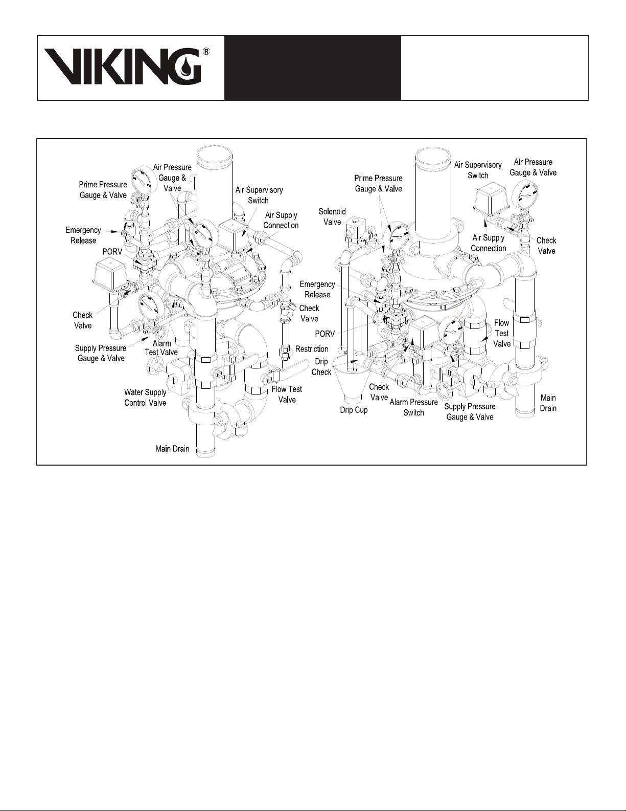
complete as shown in Figure 8. This pilot operated externally reset valve also includes
an internal check diaphragm, which eliminates the need for a separate check valve
being installed in the system riser.
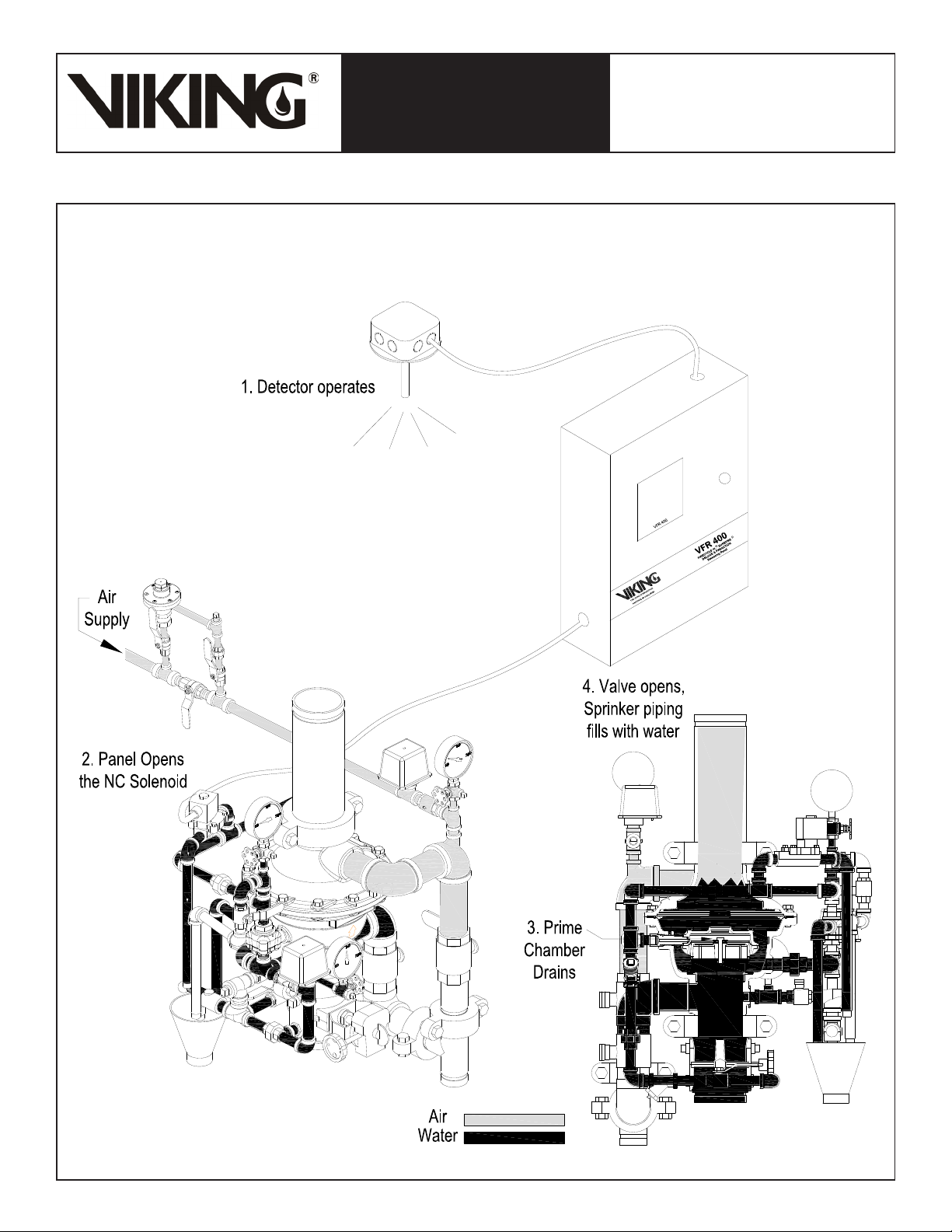
A. Viking Supervised Single-Interlocked Electric Release Preaction Systems
Utilizing the Viking G-4000P Valve
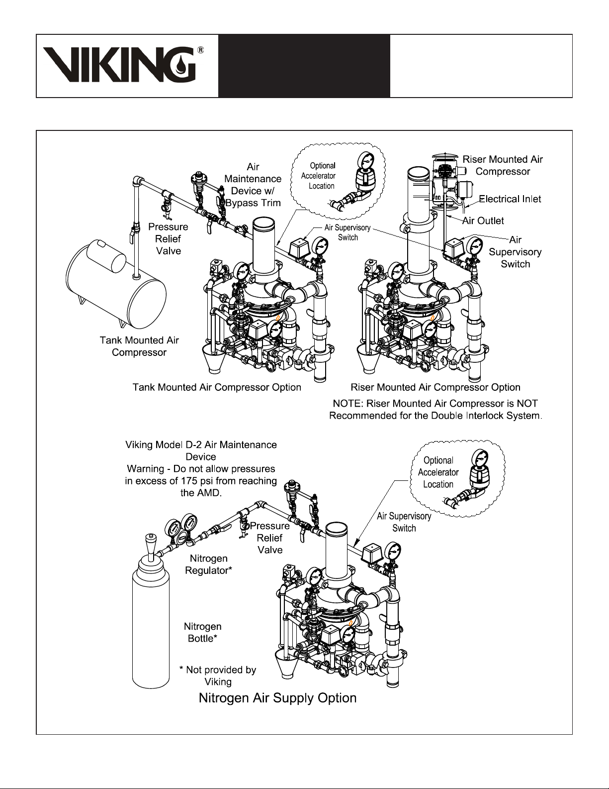
The system piping is pressurized with air or nitrogen as required by NFPA 13 for su-
pervisory purposes only. Viking recommends a minimum of 15 to 20 psi (1.0 to 1.4 bar)
for supervisory air pressure for single interlock systems (refer to Table 2 for double
interlock systems). This feature serves to prevent undetected leaks on the system pip-
ing network. If the system piping or a sprinkler is damaged, the supervisory pressure is
reduced and a “low air” supervisory alarm is activated.
Electrically released preaction systems require a 24 VDC normally closed electric so-
lenoid valve controlled by an approved release control panel with compatible detection
system. In fire conditions, when the detection system operates, the system control
panel energizes the solenoid valve open. When the solenoid opens, the priming water
is relieved from the internal prime chamber assembly. The prime chamber assembly
collapses, and water passes through the G-4000P Valve and internal check diaphragm to the system piping network. The entire
sprinkler system fills with water. The sprinkler piping will remain filled with water until a sprinkler operates.
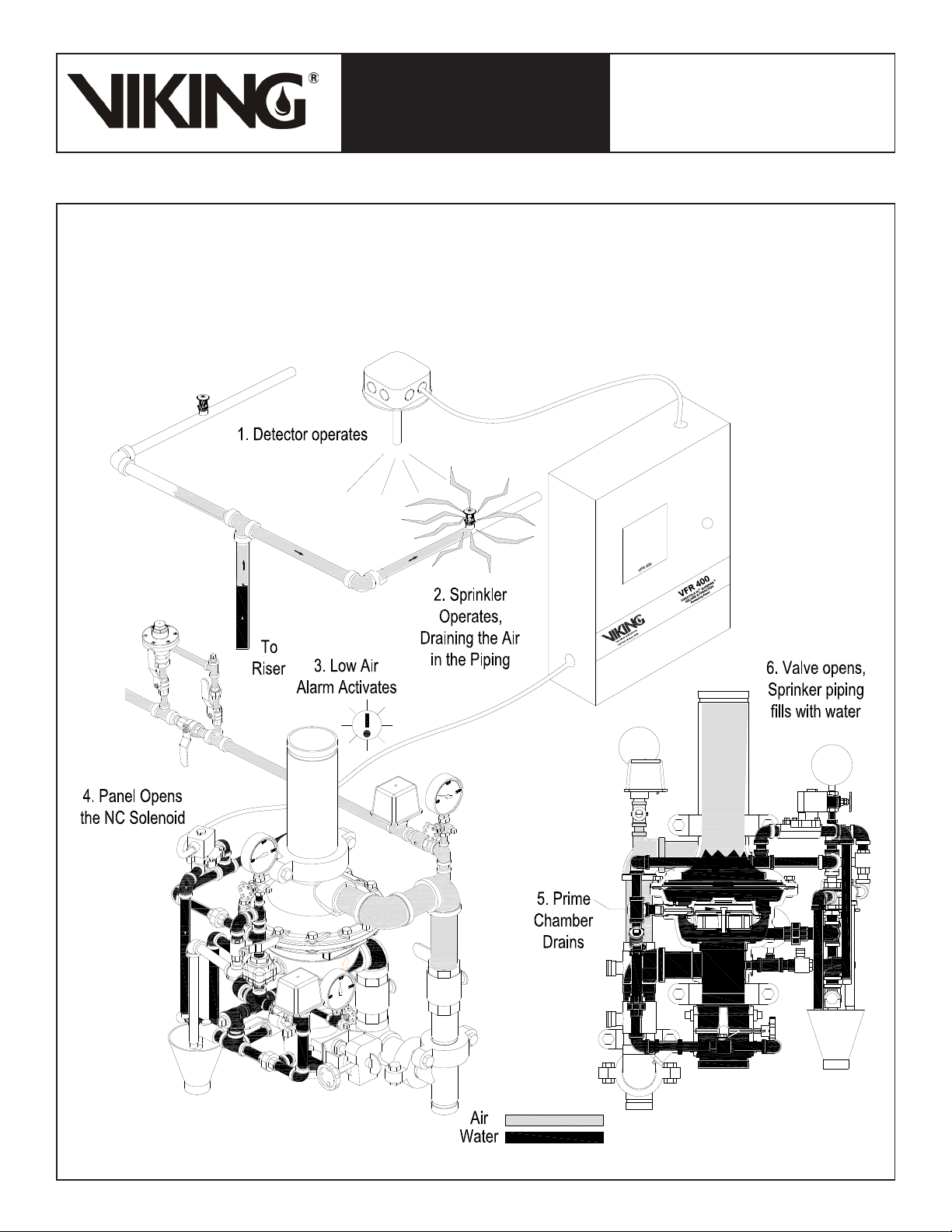
B. Viking Supervised Double-Interlocked Electric/Pneu-Lectric Release Preaction Systems Utilizing the Viking
Model G-4000P Valve.
The system piping is pressurized with air or nitrogen to serve both as a means of supervising the integrity of the piping network
and as one portion of the system release operation. This feature serves to prevent undetected leaks on the system piping net-
work. If the system piping or a sprinkler is damaged, the supervisory pressure is reduced and a “low air” supervisory alarm is
activated.
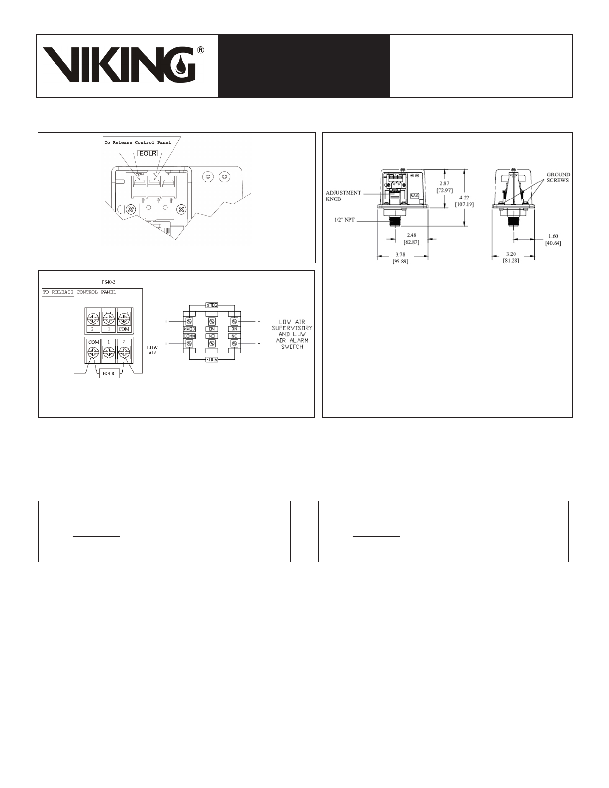
The 24 VDC normally closed electric solenoid and an additional “low air” alarm switch are connected to a compatible release24 VDC normally closed electric solenoid and an additional “low air” alarm switch are connected to a compatible releaseelectric solenoid and an additional “low air” alarm switch are connected to a compatible release
control panel and compatible detection devices. The release control panel is programmed so that a signal from both a release
device and the low air alarm switch must be received before the solenoid is allowed to open. The air pressure switch has two
independently operating connections. The high side is wired as a low air supervisory switch, and the low side is wired as low air
alarm. In fire conditions, a detection device and the low air alarm switch must operate in order to open the solenoid valve. When
the solenoid opens, priming water is relieved from the G-4000P Valve’s internal prime chamber assembly. The prime chamber
assembly is forced open by the system water supply and water passes through the G-4000P valve and internal check diaphragm
to the system piping network. The entire sprinkler system fills with water.
2. LISTING AND APPROVALS
cULus Listed: VLFT
FM Approved: Preaction Sprinkler Systems
3. TECHNICAL DATA
Specifications:
Pressure Rating: 250 PSI (17.2 Bar) Water Working Pressure
Factory Hydrostatically Tested to: 500 psi (34.5 bar)
Friction Loss (Given in feet of Schedule 40 pipe based on Hazen & Williams formula C = 120):
Model G-4000P Valve: 31.2’
12” Section of Pipe: 1’
Water Supply Control Valve: 15’
Model G-4000P Valve CCvFactor: 341
Valve Color: Black
Material Specifications:
Refer to Figure 11.
Viking Technical Data may be found on
The Viking Corporation’s Web site at
http://www.vikinggroupinc.com.
The Web site may include a more recent
edition of this Technical Data Page.
Q = Cv√∆P
S
Form No. F_111608
Q = Flow
Cv =Flow Factor (GPM/1 PSI ∆P)
∆P = Pressure Loss through Valve
S = Specific Gravity of Fluid
Revised page replaces page 325a-m, dated September 2, 2010.
(Revised figure 11 and replacement parts components.)

TECHNICAL DATA
May 28, 2013
The Viking Corporation, 210 N Industrial Park Drive, Hastings MI 49058
Telephone: 269-945-9501 Technical Services: 877-384-5464 Fax: 269-818-1680 Email: techsvcs@vikingcorp.com
Preaction 325b
4” MODEL G-4000P PREACTION
WITH ELECTRIC RELEASE
Ordering Information:
Available since 2009.
Part Number: G-4000P Electric Release Preaction System Riser
Assembly - 15651-1 (Refer to Figure 8.)
Accessories: (See figure 9.)
Drain Manifold: 15588
Model E-1 Accelerator: 08055
Model LD-1 Anti-Column Device: 14800
4. INSTALLATION:
A. General Installation Instructions
1. For proper operation and approval, the valve must be installed in the vertical position as trimmed from the factory. DO NOT
modify the factory assembled trim except as described in this technical data sheet.
2. A 12” section of pipe is provided with the G-4000P Electric Release Preaction System Riser Assembly. Prior to valve mainte-
nance, this section of pipe may be removed to provide clearance for lifting the cover from the body.
3. The Model G-4000P Valve must be installed in an area not subject to freezing temperatures or physical damage. If required,
provide a valve house (enclosure) with adequate heat around the valve and trim. Freezing temperatures will damage the
G-4000P valve. When corrosive atmospheres and/or contaminated water supplies are present, it is the owner’s responsibility
to verify compatibility with the Model G-4000P Valve and associated equipment.
4. The Viking Model E-1 Accelerator should be installed at the location indicated in Figure 1 when required. Note: The accelerator
would only be used for Double Interlock Systems.
B. Air Supply Design
1. Air Compressor Size
Viking recommends a minimum of 15 to 20 PSI (1.0 to 1.4 bar) of supervisory pressure be established within the piping network
for single interlock systems (refer to Table 2 for double interlock systems). While lower pressures are allowed by NFPA 13 for
single interlock preaction systems, maintaining higher air pressure within the system will assist maintenance personnel in finding
and isolating inadvertent or accidental leaks within the system quickly.
NFPA 13 requires that the air supply be capable of filling the entire sprinkler system to its required air pressure within 30 minutes.
A common method of sizing an air compressor is to use the following formula:
Where:
V = Volume
P = Required Air Pressure
T = Fill time (typically 30 min.)
7.48 = gal. / ft.3
14.7 = atmospheric pressure
Example:
System volume as determined by table 1 = 750 gallons
Required Air pressure = 20 psi (Single Interlock System)
Compressor
Size (cfm) =
V x P
7.48 x 14.7 x T
Therefore, the compressor shall be capable of providing 5 cfm.
Table 1 - Pipe Capacity for Sizing Air Compressors
Pipe Diameter Capacity
US International
Schedule 40 (1” to 6”)
Schedule 30 (8”) Schedule 10
Gal / Ft L / m Gal / Ft L / m
1” DN25 0.045 0.559 0.049 0.608
1-1/4” DN32 0.078 0.969 0.085 1.043
1-1/2” DN40 0.106 1.316 0.115 1.428
2” DN50 0.174 2.161 0.190 2.360
2-1/2” DN65 0.248 3.080 0.283 3.515
3” DN80 0.383 4.756 0.434 5.390
3-1/2” DN90 0.513 6.370 0.577 7.165
4” DN100 0.660 8.196 0.740 9.190
5” DN125 1.040 12.915 1.144 14.206
6” DN150 1.501 18.640 1.649 20.477
8” DN200 2.660 33.032 2.776 30.472
For Metric Units 1 Ft. = 0.3048 M, 1 Gal. = 3.785L Table 3 - Quick Reference Compressor Size
Compressor
Size (HP)
Free Air @
40 PSI (cfm)
Max System Size to
Pump to 40 psi
in 30 Minutes (Gal)
1/6 1.0 90
1/3 2.0 180
1/2 3.1 300
1 5.9 600
Table 2 - Air Pressure Settings
For Systems with Tank Mounted Compressors:
Single Interlock Double Interlock
Air Maintenance
Device 20 PSI (1.4 bar) 30 PSI (2.1 bar)
Air Pressure
Supervisory Switch 15 PSI (1.0 bar) 25 PSI (1.7 bar)
Low Air Alarm
Switch -- 20 PSI (1.4 bar)
For Systems with Riser Mounted Compressors:
Compressor On/Off
Switch
15 PSI (1.0 bar) /
25 PSI (1.7 bar)
30 PSI (2.1 bar) /
40 PSI (2.8 bar)
Air Pressure
Supervisory Switch 10 PSI (.7 bar) 25 PSI (1.7 bar)
Low Air Alarm
Switch -- 20 PSI (1.4 bar)
Compressor Size (cfm) = (750 x 20) = 4.5 cfm
7.48 x 14.7 x 30

TECHNICAL DATA
May 28, 2013
4” MODEL G-4000P PREACTION
WITH ELECTRIC RELEASE
The Viking Corporation, 210 N Industrial Park Drive, Hastings MI 49058
Telephone: 269-945-9501 Technical Services: 877-384-5464 Fax: 269-818-1680 Email: techsvcs@vikingcorp.com
Preaction 325c
Figure 1 - Air Supply Options

TECHNICAL DATA
May 28, 2013
The Viking Corporation, 210 N Industrial Park Drive, Hastings MI 49058
Telephone: 269-945-9501 Technical Services: 877-384-5464 Fax: 269-818-1680 Email: techsvcs@vikingcorp.com
Preaction 325d
4” MODEL G-4000P PREACTION
WITH ELECTRIC RELEASE
NOTE: Viking recommends tank-mounted air compressors for Double Interlock Electric/Pneu-Lectric Release Preaction Systems.
2. Nitrogen Cylinder Gas Supply (See Figure 1.)
Nitrogen may be used in place of air compressors. Nitrogen is supplied in pressurized cylinders in various sizes and pressures.
Some of the most common are 122 Cu. Ft. at 1900 PSI (3455 L at 131 bar), 225 Cu. Ft. at 2100 PSI (6372 L at 145 bar), and
280 Cu. Ft. at 2300 PSI (7930 L at 159 bar).
When nitrogen cylinders are used as a primary air supply, spare cylinders should be furnished and located at the valve location.
To determine the approximate amount of nitrogen to be furnished, the following formula may be used:
Special attention must be given to systems employing a bottled-gas supply. Because only a limited amount of gas is available,
small leaks that normally would go unnoticed in systems being supplied by mechanical compressors, can become critical to
the system’s overall performance. If the system is to function at temperatures as low as -40 °F (-40 °C), and, if bottled nitrogen
is the gas supply, the system is particularly susceptible to leakage, and special care should be taken to ensure against leaks
throughout the entire system.
C. Air Supply Installation
1. Install the required air supply as described in section 4.B. The size of the compressor and amount of air required should be de-
termined in accordance with Tables 1 - 3. The air or nitrogen supply to the preaction system must be clean, dry, and oil free.
2. Automatic air supplies must be regulated, restricted, and from a continuous source. A Viking air maintenance device should
be installed on each system equipped with a tank-mounted compressor, plant air, or nitrogen. For compressors with a ca-
pacity less than 5.5 ft3/min at 10 psig (0.154 m(0.154 m3/min at 0.69 bar), NFPA 13 does not require an air maintenance device. InNFPA 13 does not require an air maintenance device. In
addition, an air maintenance device should not be used with riser mounted compressors as this can lead to compressor “short
cycling”. Viking recommends using a tank-mounted compressor with air maintenance device. This can become critical whenThis can become critical when
accelerators are installed on the system.
D. Pressure Switch Wiring;
Wire the Alarm Pressure Switch (PS10) and Air Supervisory Switch (PS40), and adjust pressure settings as shown in Figures 2 - 4.
Figure 4 - Pressure Adjustment
Figure 2 - Alarm Pressure Switch Wiring
(Alarm Pressure Switch should be set to 5 psi)
FIELD ADJUSTMENTS:
Alarm Pressure Switch: The operating point of the switch can be
adjusted to any point between 4 PSI (0.27 bar) and 8 PSI (0.55 bar)
by turning the adjustment knob(s) clockwise to raise the actuation
point or counter-clockwise to lower the actuation point.
Air Supervisory Switch: The operating point of the switches can
be adjusted to any point between 10 PSI (0.7 bar) and 60 PSI
(4.1 bar) by turning the adjustment knob(s) clockwise to raise the
actuation point or counter-clockwise to lower the actuation point.
The high and low switches are adjusted independently.
English Units
Vc =
Vs x P Where:
Vc = Volume of Cylinder (ft3)
P = Required Nitrogen Pressure (psig)
V = Volume of System (gal)
100
Metric Units
Vc =
Vs x P Where:
Vc = Volume of Cylinder (L)
P = Required Nitrogen Pressure (bar)
V = Volume of System (L)
108
Figure 3 - Air Supervisory Switch Wiring
Single Interlock Double Interlock

TECHNICAL DATA
May 28, 2013
4” MODEL G-4000P PREACTION
WITH ELECTRIC RELEASE
The Viking Corporation, 210 N Industrial Park Drive, Hastings MI 49058
Telephone: 269-945-9501 Technical Services: 877-384-5464 Fax: 269-818-1680 Email: techsvcs@vikingcorp.com
Preaction 325e
Figure 5 - Trim Components
E. Hydrostatic Test:
The Preaction System, including Sprinkler Piping and Sprinklers shall be hydrostatically tested at 200 PSI (13.8 bar) and maintained
for two hours, in accordance with NFPA 13. Systems normally subjected to working system pressures in excess of 150 PSI (10.3 bar)
shall be tested at a pressure of 50 PSI (3.4 bar) in excess of system working pressure.
F. Placing the Valve in Service: (Refer to Figure 5.)
When the preaction system is ready to be placed in service, verify that the electric release system has been reset and is in a normal
condition.
1. Verify that the water supply main control valve (not shown) supplying the G-4000P Valve is closed.
2. Close the prime valve.
3. Open the main drain valve.
4. Open the flow test valve.
5. Drain all water from the preaction system. If the system has operated, or if water has entered the system, allow enough time
to completely drain the system.
6. Close the main drain valve.
7. Open the priming valve. Prime water pressure will enter and expand the valve’s internal diaphragm assembly onto the valve
seat, effectively closing the valve. Verify prime pressure has been established on the prime pressure gauge.
8. Establish air pressure on the system.
9. When the priming pressure has been verified as being established, slowly open the water supply control valve (not shown).
10. When flow is developed from the flow test valve, CLOSE the flow test valve.
11. Fully open the water supply main control valve.
12. Verify that no water flows from the drip check when the plunger is pushed.
13. Secure all valves in their normal operating position.
14. Reset the release control panel to clear any supervisory alarms.
15. Notify Authorities Having Jurisdiction and those in the affected area that the system is in service.
16. The system is now fully operational.
G. Operational Test:
An operational test shall be performed on the system in accordance with NFPA 13. Refer to Section 6 for Inspection and Operation
Test Procedures.

TECHNICAL DATA
May 28, 2013
The Viking Corporation, 210 N Industrial Park Drive, Hastings MI 49058
Telephone: 269-945-9501 Technical Services: 877-384-5464 Fax: 269-818-1680 Email: techsvcs@vikingcorp.com
Preaction 325f
4” MODEL G-4000P PREACTION
WITH ELECTRIC RELEASE
Figure 6 - Set Position
5. OPERATION
A. In the Set position:
Air pressure is introduced into the sprinkler piping for supervisory purposes only for single interlock systems. For double interlock
systems, air pressure is used for supervisory purposesair pressure is used for supervisory purposes and as one of the two initiation actions of the cross-zoned solenoid. PrimePrime
water is routed to the normally closed solenoid valve, and to the prime chamber. When prime water enters the prime chamber,
the prime chamber assembly is pressurized, causing it to expand downward onto the water seat.

TECHNICAL DATA
May 28, 2013
4” MODEL G-4000P PREACTION
WITH ELECTRIC RELEASE
The Viking Corporation, 210 N Industrial Park Drive, Hastings MI 49058
Telephone: 269-945-9501 Technical Services: 877-384-5464 Fax: 269-818-1680 Email: techsvcs@vikingcorp.com
Preaction 325g
Figure 7a - Activation of Release System - Single Interlock System
B. Activation of Release System (Single Interlock System):
When the detection system operates, the normally closed solenoid valve is powered open. Prime water is drained from the prime
chamber, causing the G-4000P Valve to open, filling the sprinkler piping with water. Water from the intermediate chamber of the
G-4000P Valve pressurizes the sensing end of the PORV, causing the PORV to open. The open PORV prevents water pressure
from building in the prime chamber should the solenoid close.

TECHNICAL DATA
May 28, 2013
The Viking Corporation, 210 N Industrial Park Drive, Hastings MI 49058
Telephone: 269-945-9501 Technical Services: 877-384-5464 Fax: 269-818-1680 Email: techsvcs@vikingcorp.com
Preaction 325h
4” MODEL G-4000P PREACTION
WITH ELECTRIC RELEASE
Figure 7b - Fire Condition - Double Interlock System
B. Fire Condition (Double Interlock System):
In a fire condition, operation of the detection system activates the first initiating circuit in the release control panel, causing an
alarm to activate. When a sprinkler operates, air pressure escapes from the sprinkler piping. The air supervisory switch activates
the second initiating circuit in release control panel. When BOTH initiating circuits have been activated, the release control panel
energizes solenoid valve open. With the solenoid valve open, prime water is drained from the prime chamber, causing the Model
G-4000P Valve to open, filling the sprinkler piping with water. Water from the intermediate chamber of the G-4000P Valve pres-
surizes the sensing end of the PORV, causing the PORV to open. The open PORV prevents water pressure from building in the
prime chamber should the solenoid close.

TECHNICAL DATA
May 28, 2013
4” MODEL G-4000P PREACTION
WITH ELECTRIC RELEASE
The Viking Corporation, 210 N Industrial Park Drive, Hastings MI 49058
Telephone: 269-945-9501 Technical Services: 877-384-5464 Fax: 269-818-1680 Email: techsvcs@vikingcorp.com
Preaction 325i
6. INSPECTION AND OPERATIONAL TEST
NOTICE: THE OWNER IS RESPONSIBLE FOR MAINTAINING THE FIRE PROTECTION SYSTEM AND DEVICES IN PROPER
OPERATING CONDITION. It is imperative that the system is inspected and tested on a regular basis in accordance with NFPA 25.
The frequency of the inspections may vary due to contaminated water supplies, corrosive water supplies, corrosive atmospheres, as
well as the condition of the air supply to the system. For minimum maintenance and inspection requirements, refer to NFPA 25. In ad-
dition, the Authority Having Jurisdiction may have additional maintenance, testing, and inspection requirements that must be followed.
Viking does not require internal inspection of the valve as part of routine inspection and testing. Internal maintenance is generally only
required for valve repairs and internal component replacement.
WARNING: Any system maintenance that involves placing a control valve or detection system out of service may eliminate the fire
protection capabilities of that system. Prior to proceeding, notify all Authorities Having Jurisdiction. Consideration should be given to
employment of a fire patrol in the affected areas.
A. Low Air Pressure Alarm Test: (Refer to Figure 5.)
Quarterly testing of low air alarms is recommended.
To Test Sprinkler System “Low Air Supervisory” Alarm:
1. To prevent operation of the G-4000P Valve and filling the system with water during the test, DO NOT operate the electric
detection system during the test. Consider closing the main water supply control valve.
2. Partially open the sprinkler system main drain or test connection.
3. Verify that low air alarms operate within an acceptable time period and continue without interruption.
4. Close the main drain or test connection.
5. Establish the supervisory air pressure to the recommended pressure.
6. Reset the system release control panel. The supervisory alarms should stop.
When testing is complete, return the system to service following steps 1 through 8 below.
B. Full Flow Trip Test: (Refer to Figure 5.)
Performance of a trip test is recommended annually during warm weather. Consider coordinating this test with operation testing
of the detectors.
CAUTION! PERFORMANCE OF THIS TEST WILL CAUSE THE G-4000P VALVE TO OPEN AND THE SPRINKLER SYSTEM TO
FILL WITH WATER.
To Trip Test the Electrically Controlled Preaction System:
1. Notify the Authority Having Jurisdiction and those in the area affected by the test.
2. Trip the G-4000P Valve by performing option “a” or “b” below.
Operate the electric release control system according to the manufacturer’s instructions (for the Single Interlock or
Double Interlock System) and open the sprinkler system test connection (for Double Interlock Systems).and open the sprinkler system test connection (for Double Interlock Systems)..
Operate the emergency release valve.
3. The G-4000P Valve should open, filling the sprinkler system with water. Water flow alarms should operate.
4. Open the sprinkler system main drain valve or sprinkler system test valve to verify adequate flow.
When Trip Testing is complete:
5. Perform steps 1 through 16 of section 4.F - PLACING THE SYSTEM IN SERVICE to return the system to service.
6. Notify the Authority Having Jurisdiction and those in the affected area that testing is complete.
7. MAINTENANCE
Viking does not require an internal inspection of the G-4000P Valve unless there is an indication of damage to internal components.
A. Taking the system out of service: (Refer to Figure 5.)
1. Close the water supply main control valve, placing the system out of service.
2. Open the flow test valve located in the base of the G-4000P Valve.
3. Close the air (or nitrogen) supply to the preaction system piping.
4. Close the priming valve.
5. Relieve all air pressure from the preaction system piping. If the system has operated, open the main drain valve to allow the
system to drain completely.
B. Removing the Cover from the Body: (Refer to Figures 1 & 11.)
1. Remove the 4” coupling from the top of the G-4000P Valve.
2. Remove the 12” section of pipe directly above the G-4000P Valve.G-4000P Valve.Valve.
3. Remove the air supply line from the air supervisory switch.
4. Remove the 2” coupling below the main drain.
5. Remove the 12 cover screws (12).
a.
b.

TECHNICAL DATA
May 28, 2013
The Viking Corporation, 210 N Industrial Park Drive, Hastings MI 49058
Telephone: 269-945-9501 Technical Services: 877-384-5464 Fax: 269-818-1680 Email: techsvcs@vikingcorp.com
Preaction 325j
4” MODEL G-4000P PREACTION
WITH ELECTRIC RELEASE
6. The cover and trim that is still connected may now be removed from the valve body. (It may be necessary to pry the valve
open as the diaphragm may bond itself to the cover and body over time.)
C. Removing / Replacing the Check Diaphragm: (Refer to Figure 11.)
1. The check diaphragm (10) may be lifted from the valve body (1).
2. If necessary, replace the check diaphragm (10).
D. Inspecting the Prime Chamber and Coupling for Leaks: (Refer to Figure 5.)
If desired, it is possible to set the G-4000P Valve and inspect for leaks with the cover removed.
1. Slowly open the prime valve.
2. With prime water established, partially open the main water supply control valve.
3. Visually inspect the inside of the G-4000P Valve for leaks.
4. Close the water supply control valve.
E. Removing / Replacing the Prime Coupling: (Refer to Figure 11.)
1. Open the 1/2” union on the prime line.
2. Using a wrench on the flats of the coupling (7), remove the coupling (7) from the valve body (1).
3. Inspect the coupling (7) and O-rings (5 and 6). Replace if necessary,, using the instructions in O-Ring Replacement Bulletin
F_120611.
F. Removing / Replacing the Prime Chamber Assembly: (Refer to Figure 11.)
1. The prime chamber assembly (4) is now held in place by two flanges on the outside diameter of the assembly. Slide the prime
chamber assembly (4) toward the prime line and remove from the body (1).
2. Inspect and replace if necessary.
3. Inspect the seat. The seat should be clean and free of foreign material. If the seat is damaged, the G-4000P Valve must be
replaced.
G. Re-Assembling the Valve: (Refer to Figure 11.)
1. Place the prime chamber assembly (4) in the valve body (1). Make sure the two flanges are positioned in the groove.
2. Thread the prime coupling (7) into the valve body (1). Make sure the end of the prime coupling (7) is inserted into the prime
chamber assembly (4).
3. Tighten the 1/4” socket set screw (8).
4. Lay the check diaphragm (10) into the valve body (1).
5. Position the cover onto the valve body (1), and install and tighten the cover screws (12).
6. Re-install any trim that was removed.
7. Place the valve in service by following the steps in Section 4.F.
8. AVAILABILITY
The Viking Model G-4000P Valve is available through a network of domestic and international distributors. See the Viking Corp. Web
site for closest distributor or contact The Viking Corporation.

TECHNICAL DATA
May 28, 2013
4” MODEL G-4000P PREACTION
WITH ELECTRIC RELEASE
The Viking Corporation, 210 N Industrial Park Drive, Hastings MI 49058
Telephone: 269-945-9501 Technical Services: 877-384-5464 Fax: 269-818-1680 Email: techsvcs@vikingcorp.com
Preaction 325k
Figure 8 - 15651-1 Assembly
Part Number 15651-1:
1 Model G-4000P Valve
1 Model G-4000P Electric Release
Trim (Includes NC Solenoid)
1 12” Section of Schedule 10 Pipe
and Coupling
1 Air Pressure Supervisory Switch
(PS40-2A)
1 Alarm Pressure Switch (PS10-2A)
1 Water Supply Control Valve
Accessories:
08055 Model E-1 Accelerator
14800 Model LD-1 Anti-Column Device
15588 Drain Manifold
Figure 9 - Optional Accessories

TECHNICAL DATA
May 28, 2013
The Viking Corporation, 210 N Industrial Park Drive, Hastings MI 49058
Telephone: 269-945-9501 Technical Services: 877-384-5464 Fax: 269-818-1680 Email: techsvcs@vikingcorp.com
Preaction 325l
4” MODEL G-4000P PREACTION
WITH ELECTRIC RELEASE
Figure 10 - Installation Dimensions

TECHNICAL DATA
May 28, 2013
4” MODEL G-4000P PREACTION
WITH ELECTRIC RELEASE
The Viking Corporation, 210 N Industrial Park Drive, Hastings MI 49058
Telephone: 269-945-9501 Technical Services: 877-384-5464 Fax: 269-818-1680 Email: techsvcs@vikingcorp.com
Preaction 325m
Form No. F_111608 Revised page replaces page 325a-m, dated September 2, 2010.
(Revised figure 11 and replacement parts components.)
2
3
4
5
5
6
7
8
9
1
Item
Number
Part
Number Description Material Number
Required
1 -- Body 65-45-12 Ductile Iron 1
2 -- Seat UNS-C11000 Copper or UNS-S30400 Stainless Steel 1
3 -- Anarobic Adhesive -- 1
4 16280 Prime Chamber Assembly Brass, EPDM, Nitrile, 304 Stainless Steel, Bronze Alloy 1
5 * O-Rings EPDM and Nitrile 2**
6 18306 Coupling UNS S17400 Stainless Steel 1
7 14941 Check Diaphragm EPDM 1
8 -- Cover 65-45-12 Ductile Iron 1
9 08083 1/2-13 x 1-1/2” HHS UNS-S30400 Stainless Steel 12
10 -- Data Plate Aluminum 2
11 -- Tack Alloy Carbon Steel 4
-- Replacement part not available.
Sub-Assembly
5 19145 O-Ring Replacement Kit (**Refer to O-Ring Replacement Bulletin Form No. F_120311 for instructions.)
Figure 11 - Replacement Parts
Other manuals for G-4000P
1
Table of contents
Other Viking Industrial Equipment manuals
Popular Industrial Equipment manuals by other brands

Aerotech
Aerotech PRO225SL Hardware manual

ABB
ABB HT568138 Operation manual

Afag
Afag DG 16 Assembly & operating instructions

schmersal
schmersal AZM201Z-I2-ST2-T-SD2P-A-DU Instructions for assembly and operation

Sungrow
Sungrow PVS-18RM user manual

Frick
Frick YORK Refrigeration IDC Installation operation & maintenance