A. SYSTEM DESCRIPTION
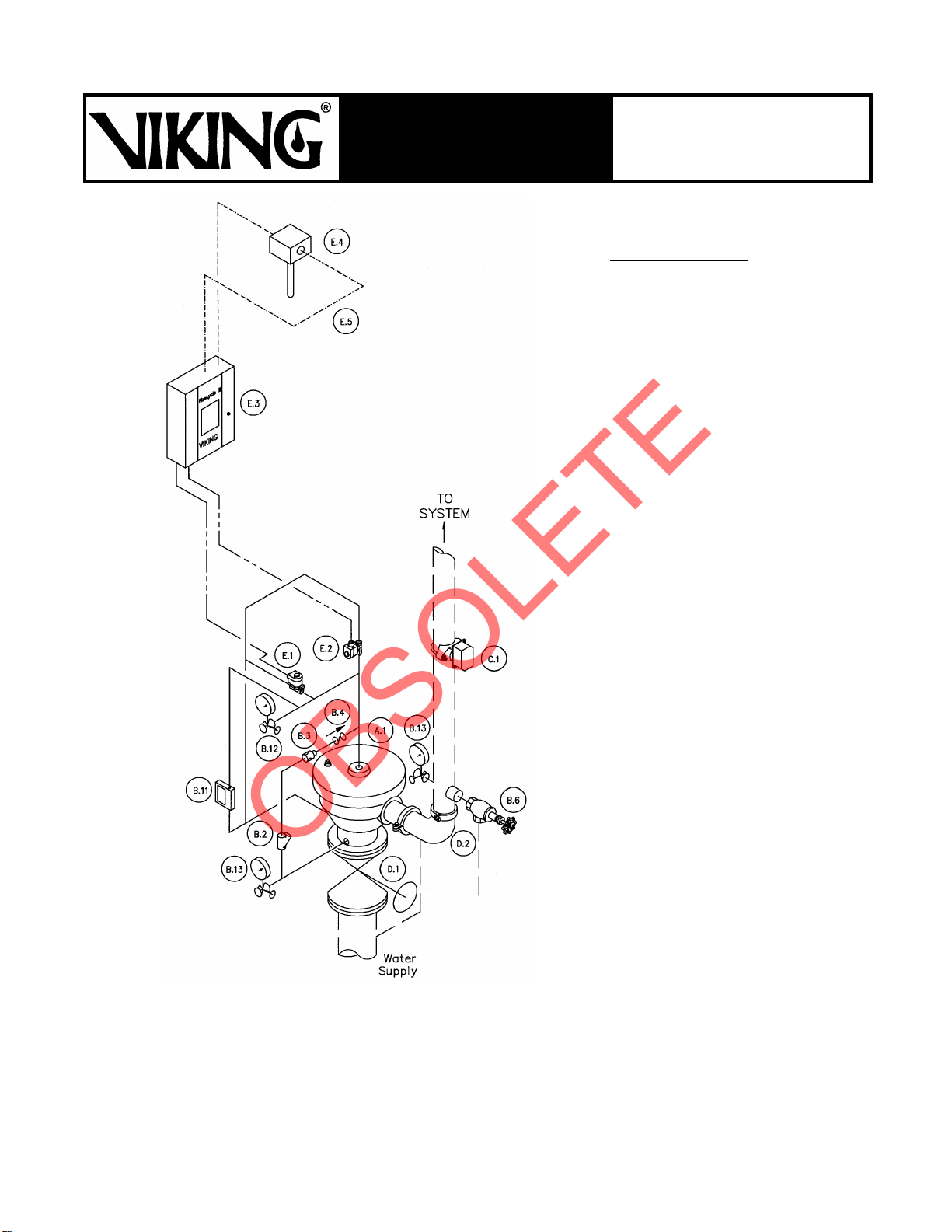
(Refer to Figure 1, page 428 c.)
The Viking Firecycle®III Cycling Wet-
pipe System utilizes a Viking Model H-1
Flow Control Valve (A.1) and a Firecy-
cle®IIIControlPanel(E.3),togetherwith
additional valves, devices and trim to
form a unique operating system.
The cycling wet configuration operates
the Firecycle®III System as a normal
wet pipe system with the ability to sense
when the fire has been controlled, and
automatically turn offthe water flow after
a preprogrammed "Soak Timer" has
been satisfied. Should the fire rekindle,
Firecycle®III will initiate the sequence
again. This unique cycling feature will
continue to operate as long as neces-
sary, provided power is available to the
panel, and helps to minimize water us-
age, water damage, and the danger of
pollution to surrounding areas. Batteries
areavailableto provideup toninety(90)
hours of emergency power. If the AC
power fails and the battery backup
power expires while the system is oper-
ating, the deluge system will "fail-safe",
and continue flowing until AC power is
restoredor the system is manually shut-
off.
The Firecycle® III Cycling Wetpipe Sys-
tem has several "fail-safe" features
which are not available on standard wet
pipe systems. Refer to Section B "Sys-
tem Operation" for details.
Wetpipe systems are commonly used
where, when the system operates, it is
desirable to discharge water immedi-
ately from any sprinklers on the system
which may have operated, as in a fire.
Consult all Authorities Having Jurisdic-
tion prior to installing a Firecycle®III
Wetpipe System. The system requires
use of a Viking Flow Control Valve and
trim kit with two Electric Release Sole-
noid Valves (E.1 and E.2) controlled by
the Firecycle®III Control Panel (E.3),
Firecycle®
Detectors(E.4),andDetector
Cable (E.5). The detector temperature
must be lower than the lowest tempera-
ture-rated sprinkler being used. For
properlocation,spacing,andpositioning
of detectors, refer to technical data de-
scribing Viking Firecycle®Detectors.
In fire conditions, when the detection
system (E.4) operates, the Firecycle®III
Control Panel (E.3) energizes normally
closed ReleaseSolenoid Valve #1 (E.1)
open, and energizes normally open Re-
lease Solenoid Valve #2 (E.2) closed,
causing Flow Control Valve (A.1) to
open, allowing water to flow through the
system piping. Water will flow from any
sprinklers attached to the system which
may have operated. When downstream
water pressure exceeds water supply
pressure, the Flow Control Valve (A.1)
performs as a hydraulically operated
check valve to prevent reverse flow.
NOTE: Firecycle®III is a complete sys-
tem, and is listed as a unit. As such, it
is normally not possible to modify the
components of the system controls or
theirinter-relationwithoutcompromising
the listing.
For information on current approvals
and permissible modifications to Firecy-
cle®III, contact The Viking Corporation,
Hastings, Michigan 49058 USA, Atten-
tion: Sales Department.
B. SYSTEM OPERATION
(Refer to Figure 1, page 428 c.)
In the NORMAL condition:
System water supply pressure enters
the primingchamber of theFlowControl
Valve (A.1) through the 1/4" (8 mm)
priming line which includes a Strainer
(B.2), restricted orifice (B.3) and Check
Valve (B.4). Normally open Release So-
lenoid Valve #2 (E.2) allows priming
water to escape so that the Flow Control
Valve (A.1) will not set, but remain open,
filling the system piping with water.
In Fire conditions:
In fire conditions, when the Firecycle®III
detection system (E.4 and E.5) oper-
ates, the Firecycle®III Control Panel
(E.3) activates a piezo sounder and en-
ergizes normally closed Release Sole-
noid Valve #1 (E.1) open and normally
open Release Solenoid Valve #2 (E.2)
closed. Pressure continues to be re-
leased from the priming chamber faster
than it is supplied through the restricted
orifice (B.3). The Flow Control Valve
(A.1) clapper remains fully open to allow
water to flow through the system piping
and to activate alarm devices, including
a Water Flow Alarm Switch (C.1). Water
willimmediatelyflowfromany sprinklers
attached to the system which may have
operated. Water Flow Alarm Switch
(C.1) activates, latching normally open
Release Solenoid Valve #2 (E.2)
closed. Water discharges until all
Firecycle®Detectorshavereset (cooled
below their set point). After all detectors
have reset, the Firecycle®III Control
Panel (E.3) activates the "Soak Timer",
allowing the system to continue dis-
charging water for a preset time period.
When the "Soak Timer" has expired,the
Firecycle®III Control Panel (E.3) de-en-
ergizes normally closed Release Sole-
noid Valve #1 (E.1), allowing it to close.
(The normally open Release Solenoid
Valve #2 (E.2) remains energized
closed until the Firecycle®III Control
Panel is manually reset, or both AC
power and battery backup have failed.)
The Flow Control Valve (A.1) re-primes
and closes, stopping the flow of water
through the system piping.
Should a Firecycle®Detector go into
alarmat this time, the Firecycle®IIICon-
trol Panel (E.3) re-energizes normally
closed ReleaseSolenoid Valve #1 (E.1)
open, and the entire cycle repeats.
To return the system to "Normal" condi-
tions, drain the system piping and re-
place any sprinklers which may have
operated, and any Firecycle®Detectors
which have been damaged. Open the
Emergency Release (B.11) to allow the
system pressure to return to normal.
Once the pressure has stabilized, close
the Emergency Release (B.11) and
press the "System Reset" button on the
Firecycle®III Control Panel (E.3).
Trouble conditions:
If the detection system is damaged or
malfunctions, the Firecycle®III Control
Panel will initiate theappropriatealarms,
and the Flow Control Valve (A.1) will
open. Water will not flow from any sprin-
klers until a sprinkler hasoperated, as in
a fire. The cycling function of theFirecy-
cle®III System will not operate in this
condition, and the system must be
manuallyshutoff. Allalarmswilloperate
normally.
If the piping system is damaged suffi-
ciently to activate the Water Flow Alarm
Switch (C.1), the Firecycle®III Control
Panel (E.3) will energize normally open
Release Solenoid Valve #2 (E.2)
closed. Because a detector has not
gone into alarm mode, Release Sole-
noid Valve #1 (E.1) will remain ener-
gized closed. The Flow Control Valve
(A.1) willre-prime andcloseafterashort
delay. This feature ensures that should
a sprinkler or the system piping become
damaged, the amount of water which
will discharge is limited by the system
pressure and the location of the system
Form No. F_100696
Firecycle®III 428 a
SYSTEM DATA
September 28, 1998
For technical data,
installation, maintenance,
and testing instructions
for individual system
components, refer to current
Viking technical data
describing individual
components of the
system being used.
Viking technical data may be found on
The Viking Corporation’s Web site at
http://www.vikingcorp.com.
The Web site may include a more recent
edition of this technical data page.
FIRECYCLE®III
CYCLING WET PIPE
SYSTEM Pat. Pend.
Replaces page 428a-d, dated August 1, 1997
(updated title block to reflect patent pending).