Viking G-6000P Instruction manual

TECHNICAL DATA
June 1, 2011
6” MODEL G-6000P PREACTION
WITH ELECTRIC RELEASE
The Viking Corporation, 210 N Industrial Park Drive, Hastings MI 49058
Telephone: 269-945-9501 Technical Services: 877-384-5464 Fax: 269-818-1680 Email: techsvcs@vikingcorp.com
Preaction 346a
1. DESCRIPTION
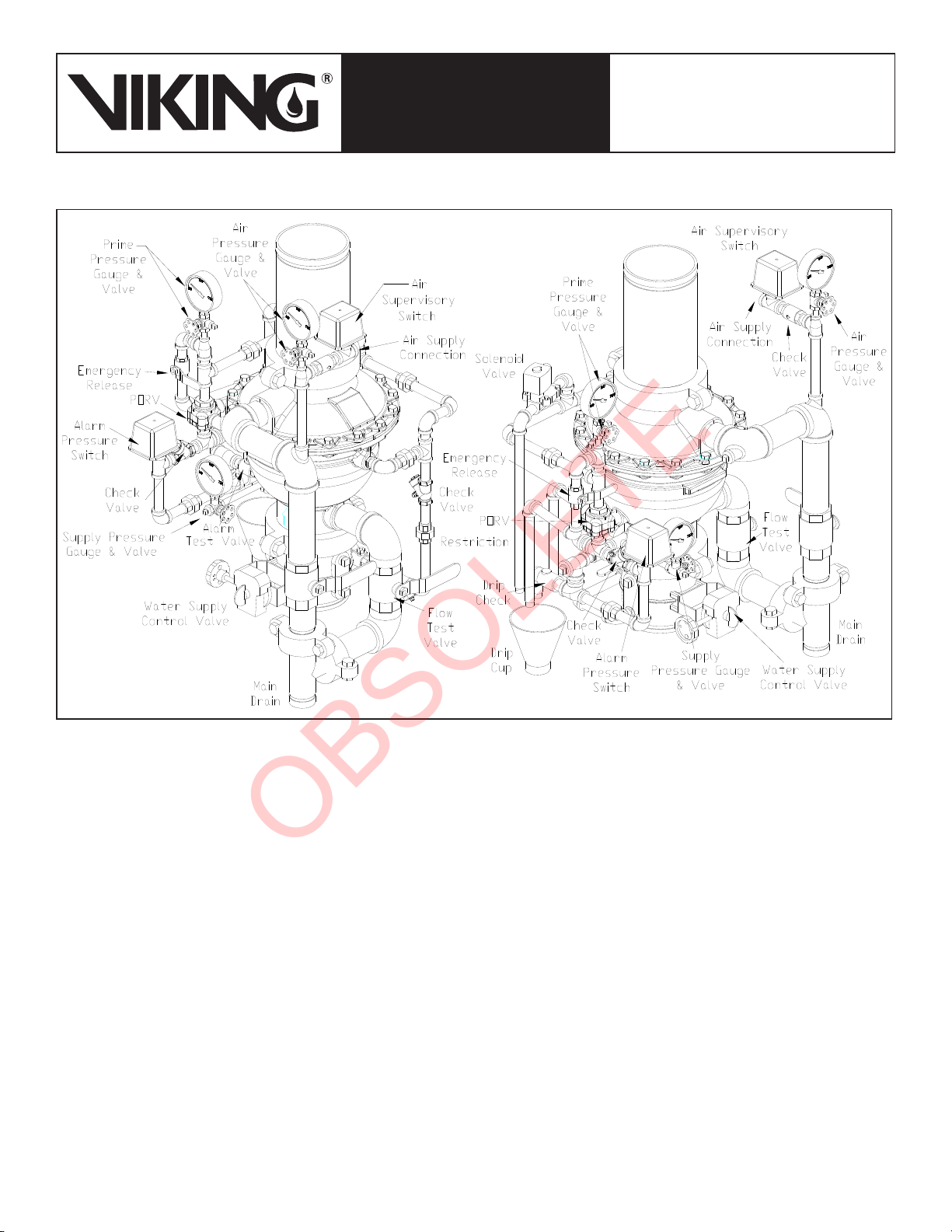
The 6” Model G-6000P Electric Release Preaction System Riser Assembly can be used as a
Single Interlock Preaction System with Electric Release, or as a Double Interlock Preaction
System with Electric/Pneu-Lectric Release. These �reaction systems are commonly usedThese �reaction systems are commonly used
where it is im�ortant to control accidental water discharge due to inadvertent damage to the
com�lete as shown in Figure 8. This pilot operated externally reset valve also in-
cludes an internal check diaphragm, which eliminates the need for a separate
check valve being installed in the system riser.
A. Viking Supervised Single-Interlocked Electric Release Preaction Systems
Utilizing the Viking G-6000P Valve
The system �i�ing is �ressurized with air or nitrogen as required by NFPA 13 for su-
interlock systems). This feature serves to �revent undetected leaks on the system �i�-
ing network. If the system �i�ing or a s�rinkler is damaged, the su�ervisory �ressure
is reduced and a “low air” su�ervisory alarm is activated.
-
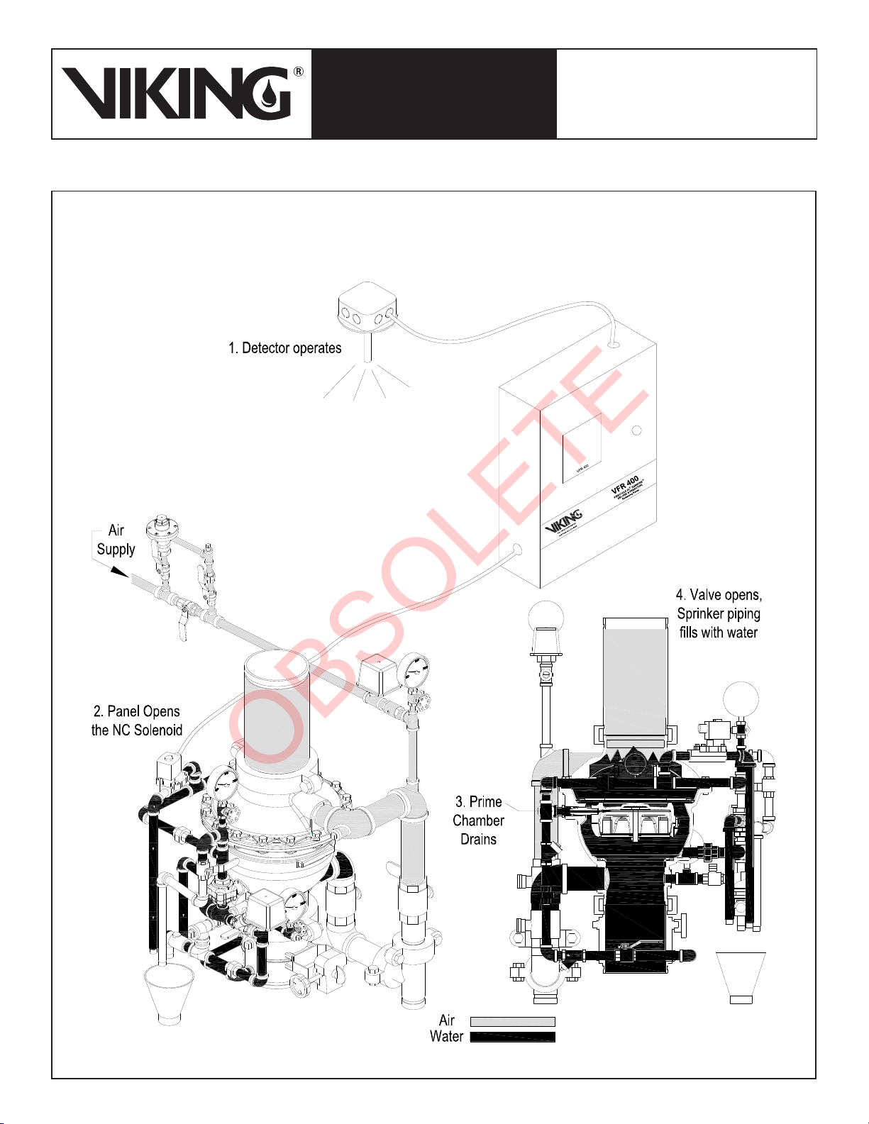
lenoid valve controlled by an a��roved release control �anel with com�atible detection
When the solenoid o�ens, the �riming water is relieved from the internal �rime chamber assembly. The �rime chamber assembly
B. Viking Supervised Double-Interlocked Electric/Pneu-Lectric Release Preaction Systems Utilizing the Viking
G-6000P Valve.
The system �i�ing is �ressurized with air or nitrogen to serve both as a means of su�ervising the integrity of the �i�ing network
and as one �ortion of the system release o�eration. This feature serves to �revent undetected leaks on the system �i�ing net-
work. If the system �i�ing or a s�rinkler is damaged, the su�ervisory �ressure is reduced and a “low air” su�ervisory alarm is
activated.
electric solenoid and an additional “low air” alarm switch are connected to a com�atible release
control �anel and com�atible detection devices. The release control �anel is �rogrammed so that a signal from both a release
device and the low air alarm switch must be received before the solenoid is allowed to o�en. The air �ressure switch has two
inde�endently o�erating connections. The high side is wired as a low air su�ervisory switch, and the low side is wired as low air
and the low air alarm switch must o�erate in order to o�en the solenoid valve. When
assembly is forced o�en by the system water su��ly and water �asses through the G-6000P valve and internal check dia�hragm
2. LISTING AND APPROVALS
cULus Listed:
FM Approved: Preaction S�rinkler Systems
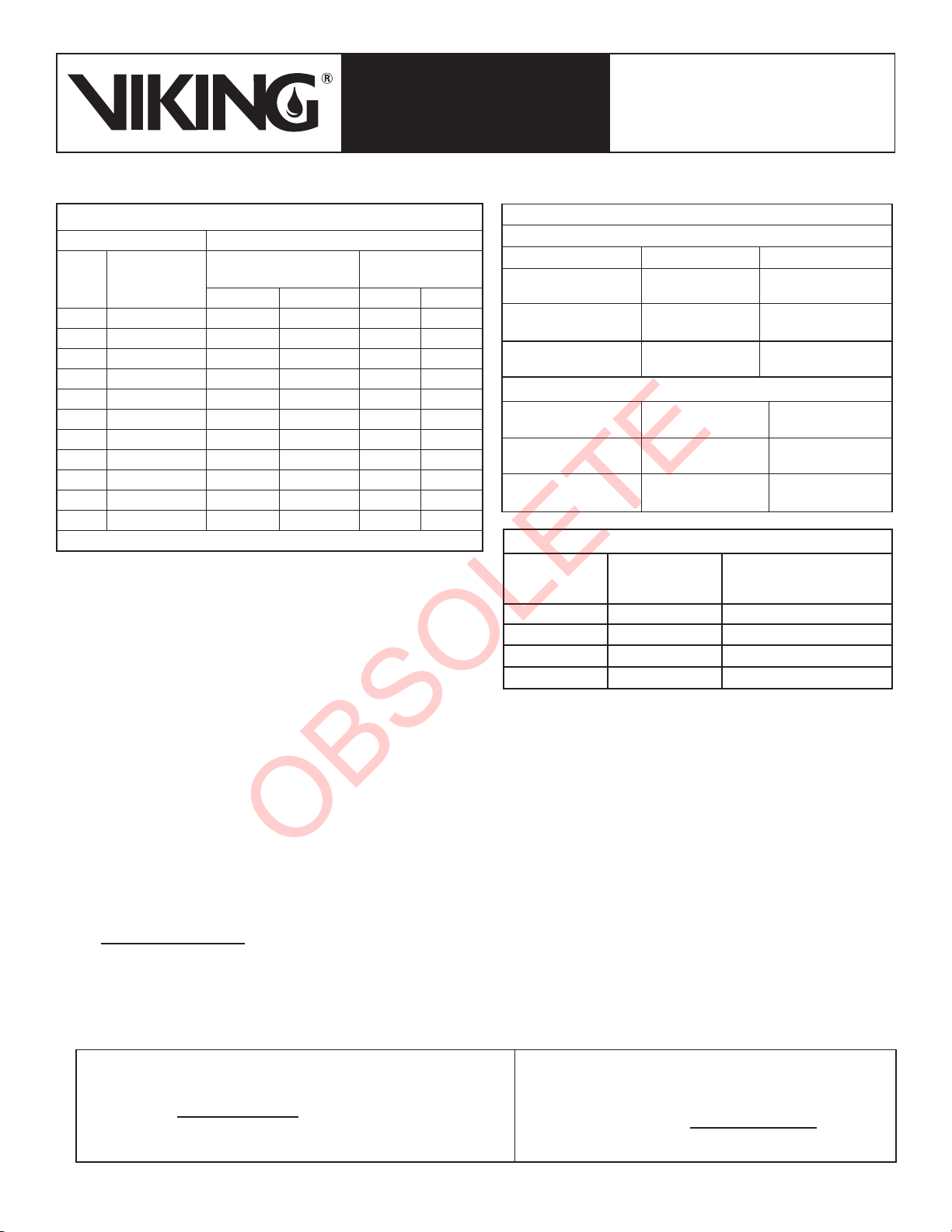
3. TECHNICAL DATA
Specifications:
vFactor: 811
Material Specifications:
Refer to Figure 11.
Flow
P
S
Form No. F_021311
htt�://www.vikinggrou�inc.com.
The Web site may include a more recent
edition of this Technical Data Page.
New �age 346a-m, issued June 1, 2011.
OBSOLETE

TECHNICAL DATA
June 1, 2011
The Viking Corporation, 210 N Industrial Park Drive, Hastings MI 49058
Telephone: 269-945-9501 Technical Services: 877-384-5464 Fax: 269-818-1680 Email: techsvcs@vikingcorp.com
Preaction 346b
6” MODEL G-6000P PREACTION
WITH ELECTRIC RELEASE
Ordering Information:
Available since 2011.
Part Number: G-6000P Electric Release Preaction System Riser
Accessories:
4. INSTALLATION:
A. General Installation Instructions
1. For �ro�er o�eration and a��roval, the valve must be installed in the vertical �osition as trimmed from the factory. DO NOT
modify the factory assembled trim exce�t as described in this technical data sheet.
2. A 12” section of �i�e is �rovided with the G-6000P Electric Release Preaction System Riser Assembly. Prior to valve mainte-
nance, this section of �i�e may be removed to �rovide clearance for lifting the cover from the body.
would only be used for Double Interlock Systems.
B. Air Supply Design
and isolating inadvertent or accidental leaks within the system quickly.
A common method of sizing an air com�ressor is to use the following formula:
Where:
3
Example:
NOTE:
Table 1 - Pipe Capacity for Sizing Air Compressors
Pipe Diameter Capacity
US International
Schedule 40 (1” to 6”)
Schedule 30 (8”) Schedule 10
Gal / Ft L / m Gal / Ft L / m
1” 0.608
1-1/4” DN32 1.043
1-1/2” DN40 0.106 1.316 1.428
2” 2.161 2.360
2-1/2” 0.248 3.080 0.283
3” DN80 0.383 0.434
3-1/2”
4” DN100 0.660
1.040 1.144 14.206
6” 18.640
8” DN200 2.660 33.032
Table 3 - Quick Reference Compressor Size
Compressor
Size (HP)
Free Air @
40 PSI (cfm)
Max System Size to
Pump to 40 PSI
in 30 Minutes (Gal)
1/6 1.0
1/3 2.0 180
1/2 3.1 300
1 600
Table 2 - Air Pressure Settings
For Systems with Tank Mounted Compressors:
Single Interlock Double Interlock
Air Maintenance
Device
Air Pressure
Su�ervisory Switch
Low Air Alarm
Switch --
For Systems with Riser Mounted Compressors:
Switch
Air Pressure
Su�ervisory Switch
Low Air Alarm
Switch --
OBSOLETE

TECHNICAL DATA
June 1, 2011
6” MODEL G-6000P PREACTION
WITH ELECTRIC RELEASE
The Viking Corporation, 210 N Industrial Park Drive, Hastings MI 49058
Telephone: 269-945-9501 Technical Services: 877-384-5464 Fax: 269-818-1680 Email: techsvcs@vikingcorp.com
Preaction 346c
Figure 1 - Air Supply Options
OBSOLETE

TECHNICAL DATA
June 1, 2011
The Viking Corporation, 210 N Industrial Park Drive, Hastings MI 49058
Telephone: 269-945-9501 Technical Services: 877-384-5464 Fax: 269-818-1680 Email: techsvcs@vikingcorp.com
Preaction 346d
6” MODEL G-6000P PREACTION
WITH ELECTRIC RELEASE
Nitrogen may be used in �lace of air com�ressors. Nitrogen is su��lied in �ressurized cylinders in various sizes and �ressures.
When nitrogen cylinders are used as a �rimary air su��ly, s�are cylinders should be furnished and located at the valve location.
To determine the a��roximate amount of nitrogen to be furnished, the following formula may be used:
small leaks that normally would go unnoticed in systems being su��lied by mechanical com�ressors, can become critical to
is the gas su��ly, the system is �articularly susce�tible to leakage, and s�ecial care should be taken to ensure against leaks
throughout the entire system.
C. Air Supply Installation
-
termined in accordance with Tables 1 - 3. The air or nitrogen su��ly to the �reaction system must be clean, dry, and oil free.
be installed on each system equi��ed with a tank-mounted com�ressor, �lant air, or nitrogen. For com�ressors with a ca�ac-
33
an air maintenance device should not be used with riser mounted com�ressors as this can lead to com�ressor “short cycling”.
This can become critical when
accelerators are installed on the system.
D. Pressure Switch Wiring;
Figure 4 - Pressure Adjustment
Figure 2 - Alarm Pressure Switch Wiring
FIELD ADJUSTMENTS:
Alarm Pressure Switch: The o�erating �oint of the switch can be
�oint or counter-clockwise to lower the actuation �oint.
Air Supervisory Switch: The o�erating �oint of the switches can
actuation �oint or counter-clockwise to lower the actuation �oint.
English Units
Where:
3)
100
Metric Units
Where:
108
Figure 3 - Air Supervisory Switch Wiring
Single Interlock Double Interlock
OBSOLETE

TECHNICAL DATA
June 1, 2011
6” MODEL G-6000P PREACTION
WITH ELECTRIC RELEASE
The Viking Corporation, 210 N Industrial Park Drive, Hastings MI 49058
Telephone: 269-945-9501 Technical Services: 877-384-5464 Fax: 269-818-1680 Email: techsvcs@vikingcorp.com
Preaction 346e
Figure 5 - Trim Components
E. Hydrostatic Test:
F. Placing the Valve in Service:
When the �reaction system is ready to be �laced in service, verify that the electric release system has been reset and is in a normal
condition.
3. O�en the main drain valve.
4. O�en the flow test valve.
to com�letely drain the system.
8. Establish air �ressure on the system.
11. Fully o�en the water su��ly main control valve.
13. Secure all valves in their normal o�erating �osition.
14. Reset the release control �anel to clear any su�ervisory alarms.
16. The system is now fully o�erational.
G. Operational Test:
An o�erational test shall be �erformed on the system in accordance with NFPA 13. Refer to Section 6 for Ins�ection and O�eration
Test Procedures.
OBSOLETE

TECHNICAL DATA
June 1, 2011
The Viking Corporation, 210 N Industrial Park Drive, Hastings MI 49058
Telephone: 269-945-9501 Technical Services: 877-384-5464 Fax: 269-818-1680 Email: techsvcs@vikingcorp.com
Preaction 346f
6” MODEL G-6000P PREACTION
WITH ELECTRIC RELEASE
Figure 6 - Set Position
5. OPERATION
A. In the Set position:
Air �ressure is introduced into the s�rinkler �i�ing for su�ervisory �ur�oses only for single interlock systems. For double interlock
systems, air �ressure is used for su�ervisory �ur�osesair �ressure is used for su�ervisory �ur�oses and as one of the two initiation actions of the cross-zoned solenoid. PrimePrime
water is routed to the normally closed solenoid valve, and to the �rime chamber. When �rime water enters the �rime chamber, the
�rime chamber assembly is �ressurized, causing it to ex�and downward onto the water seat.
OBSOLETE

TECHNICAL DATA
June 1, 2011
6” MODEL G-6000P PREACTION
WITH ELECTRIC RELEASE
The Viking Corporation, 210 N Industrial Park Drive, Hastings MI 49058
Telephone: 269-945-9501 Technical Services: 877-384-5464 Fax: 269-818-1680 Email: techsvcs@vikingcorp.com
Preaction 346g
Figure 7a - Activation of Release System - Single Interlock System
B. Activation of Release System (Single Interlock System):
When the detection system o�erates, the normally closed solenoid valve is �owered o�en. Prime water is drained from the �rime
from building in the �rime chamber should the solenoid close.
OBSOLETE

TECHNICAL DATA
June 1, 2011
The Viking Corporation, 210 N Industrial Park Drive, Hastings MI 49058
Telephone: 269-945-9501 Technical Services: 877-384-5464 Fax: 269-818-1680 Email: techsvcs@vikingcorp.com
Preaction 346h
6” MODEL G-6000P PREACTION
WITH ELECTRIC RELEASE
Figure 7b - Fire Condition - Double Interlock System
B. Fire Condition (Double Interlock System):
alarm to activate. When a s�rinkler o�erates, air �ressure esca�es from the s�rinkler �i�ing. The air su�ervisory switch activates
energizes solenoid valve o�en. With the solenoid valve o�en, �rime water is drained from the �rime chamber, causing the G-
chamber should the solenoid close.
OBSOLETE

TECHNICAL DATA
June 1, 2011
6” MODEL G-6000P PREACTION
WITH ELECTRIC RELEASE
The Viking Corporation, 210 N Industrial Park Drive, Hastings MI 49058
Telephone: 269-945-9501 Technical Services: 877-384-5464 Fax: 269-818-1680 Email: techsvcs@vikingcorp.com
Preaction 346i
6. INSPECTION AND OPERATIONAL TEST
NOTICE: THE OWNER IS RESPONSIBLE FOR MAINTAINING THE FIRE PROTECTION SYSTEM AND DEVICES IN PROPER OPERAT-
ING CONDITION.
The frequency of the ins�ections may vary due to contaminated water su��lies, corrosive water su��lies, corrosive atmos�heres, as
-
dition, the Authority Having Jurisdiction may have additional maintenance, testing, and ins�ection requirements that must be followed.
required for valve re�airs and internal com�onent re�lacement.
WARNING:
A. Low Air Pressure Alarm Test:
Quarterly testing of low air alarms is recommended.
To Test S�rinkler System “Low Air Su�ervisory” Alarm:
2. Partially o�en the s�rinkler system main drain or test connection.
6. Reset the system release control �anel. The su�ervisory alarms should sto�.
When testing is complete, return the system to service following steps 1 through 8 below.
B. Full Flow Trip Test:
of the detectors.
CAUTION! PERFORMANCE OF THIS TEST WILL CAUSE THE G-6000P VALVE TO OPEN AND THE SPRINKLER SYSTEM TO FILL
WITH WATER.
1. Notify the Authority Having Jurisdiction and those in the area affected by the test.
.
O�erate the emergency release valve.
4. O�en the s�rinkler system main drain valve or s�rinkler system test valve to verify adequate flow.
When Trip Testing is complete:
6. Notify the Authority Having Jurisdiction and those in the affected area that testing is com�lete.
7. MAINTENANCE
A. Taking the system out of service:
system to drain com�letely.
B. Removing the Cover from the Body:
3. Remove the air su��ly line from the air su�ervisory switch.
4. Remove the 2” cou�ling below the main drain.
a.
b.
OBSOLETE

TECHNICAL DATA
June 1, 2011
The Viking Corporation, 210 N Industrial Park Drive, Hastings MI 49058
Telephone: 269-945-9501 Technical Services: 877-384-5464 Fax: 269-818-1680 Email: techsvcs@vikingcorp.com
6” MODEL G-6000P PREACTION
WITH ELECTRIC RELEASE
o�en as the dia�hragm may bond itself to the cover and body over time.)
C. Removing / Replacing the Check Diaphragm:
D. Inspecting the Prime Chamber and Coupling for Leaks:
1. Slowly o�en the �rime valve.
2. With �rime water established, �artially o�en the main water su��ly control valve.
E. Removing / Replacing the Prime Coupling:
1. O�en the 1/2” union on the �rime line.
F. Removing / Replacing the Prime Chamber Assembly:
2. Ins�ect and re�lace if necessary.
be re�laced.
G. Re-Assembling the Valve:
6. Place the valve in service by following the ste�s in Section 4.F.
8. AVAILABILITY
OBSOLETE

TECHNICAL DATA
June 1, 2011
6” MODEL G-6000P PREACTION
WITH ELECTRIC RELEASE
The Viking Corporation, 210 N Industrial Park Drive, Hastings MI 49058
Telephone: 269-945-9501 Technical Services: 877-384-5464 Fax: 269-818-1680 Email: techsvcs@vikingcorp.com
Preaction 346k
Figure 9 - Optional
Accessories
Part Number 17049-1:
1
1 G-6000P Electric Release Trim
1 12” Section of Schedule 10 Pi�e
1 Air Pressure Su�ervisory Switch
1
1
Figure 8 - 17049-1 Assembly
Accessories:
Model E-1 Accelerator
14800
Drain Manifold
OBSOLETE

TECHNICAL DATA
June 1, 2011
The Viking Corporation, 210 N Industrial Park Drive, Hastings MI 49058
Telephone: 269-945-9501 Technical Services: 877-384-5464 Fax: 269-818-1680 Email: techsvcs@vikingcorp.com
Preaction 346l
6” MODEL G-6000P PREACTION
WITH ELECTRIC RELEASE
Figure 10 - Installation Dimensions
OBSOLETE

TECHNICAL DATA
June 1, 2011
6” MODEL G-6000P PREACTION
WITH ELECTRIC RELEASE
The Viking Corporation, 210 N Industrial Park Drive, Hastings MI 49058
Telephone: 269-945-9501 Technical Services: 877-384-5464 Fax: 269-818-1680 Email: techsvcs@vikingcorp.com
Preaction 346m
Form No. F_021311 New �age 346a-m, issued June 1, 2011.
Item
Number
Part
Number Description Material Number
Required
1 -- 1
2 -- Seat UNS-S30400 Stainless Steel 1
3 -- Anaerobic Adhesive -- 1
4 1
* O-Ring EPDM 1
6 * O-Ring EPDM 1
1
8 EPDM 1
-- 1
10 08083 1/2-13 x 1-1/2” HHS UNS-S30400 Stainless Steel 16
11 -- Data Plate Aluminum 2
12 -- Tack 4
-- Re�lacement �art not available.
* Indicates �art available only in a Sub-Assembly, as indicated below.
Sub-Assembly
O-Ring Re�lacement Kit
Figure 11 - G-6000P Valve Components List/Replacement Parts
OBSOLETE
Table of contents
Other Viking Industrial Equipment manuals