manuals.online logo
Brands
  1. Home
  2. •
  3. Brands
  4. •
  5. Viking
  6. •
  7. Irrigation System
  8. •
  9. Viking QR1 Operating manual

Viking QR1 Operating manual

QUICK RESPONSE
SPRINKLERS
GENERAL CARE, INSTALLATION,
AND MAINTENANCE GUIDE
TECHNICAL DATA
May 19, 2006
Use only the special wrench designed
for installing coated and recessed Viking
sprinklers (any other wrench may dam-
age the unit).
Use care when locating sprinklers near
fixtures that can generate heat. Do
not install sprinklers where they could
be exposed to temperatures exceeding
the maximum recommended ambient
temperature for the temperature rating
used.
Wet-pipe systems must be provided
with adequate heat. Sprinklers supplied
from dry systems in areas subject to
freezing must be listed dry sprinklers, or
upright or horizontal sidewall sprinklers
installed so that water is not trapped.
For dry systems, pendent sprinklers
and sidewall sprinklers installed on re-
turn bends are permitted, where the
sprinklers, return bend, and branch line
piping are in an area maintained at or
above 40 °F (4 °C).
6. INSTALLATION
WARNING: Viking sprinklers are manu-
factured and tested to meet the rigid re-
quirements of approving agencies. The
sprinklers are designed to be installed in
accordance with recognized installation
standards. Deviation from the standards
or any alteration to sprinklers or cover
plate assemblies after they leave the
factory including, but not limited to:
painting, plating, coating, or modifica-
tion, may render them inoperative and
will automatically nullify the approvals
and any guarantee made by Viking.
Viking sprinklers are to be installed
in accordance with the latest edi-
tion of Viking technical data, the
latest standards of NFPA, FM Global,
LPCB, Assemblee Pleniere, VdS or
other similar organizations, and also
with the provisions of governmental
codes, ordinances, and standards,
whenever applicable. The sprinkler
technical data page may contain
installation requirements specific
for the sprinkler model selected.
The use of quick response sprinklers
may be limited due to occupancy
and hazard. Refer to the Authority
Having Jurisdiction prior to installa-
tion. NOTE: QR concealed sprinklers
must be installed in neutral or nega-
tive pressure plenums only.
Before installation, be sure to have the
1. PRODUCT NAME
Viking Quick Response Sprinklers -
General Care, Installation, and Mainte-
nance Guide
2. MANUFACTURER
THE VIKING CORPORATION
210 N. Industrial Park Road
Hastings, Michigan 49058 U.S.A.
Telephone: (269) 945-9501
(877) 384-5464
Fax: (269) 945-9599
e-mail: [email protected]
3. PRODUCT DESCRIPTION
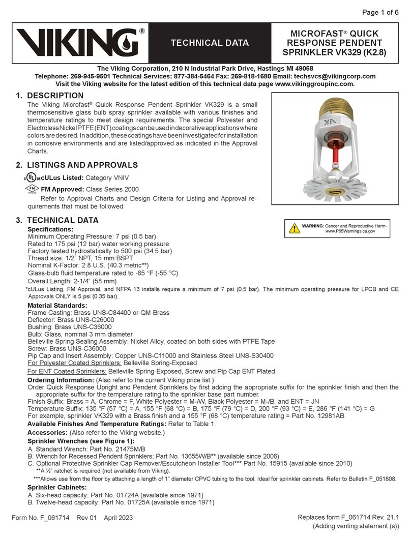
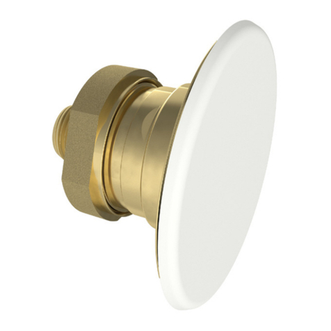
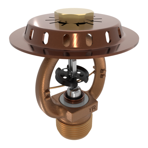
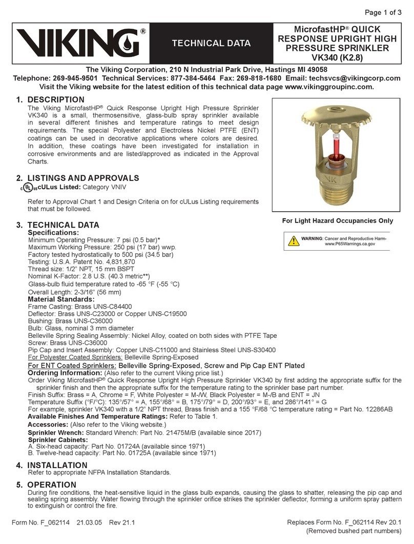
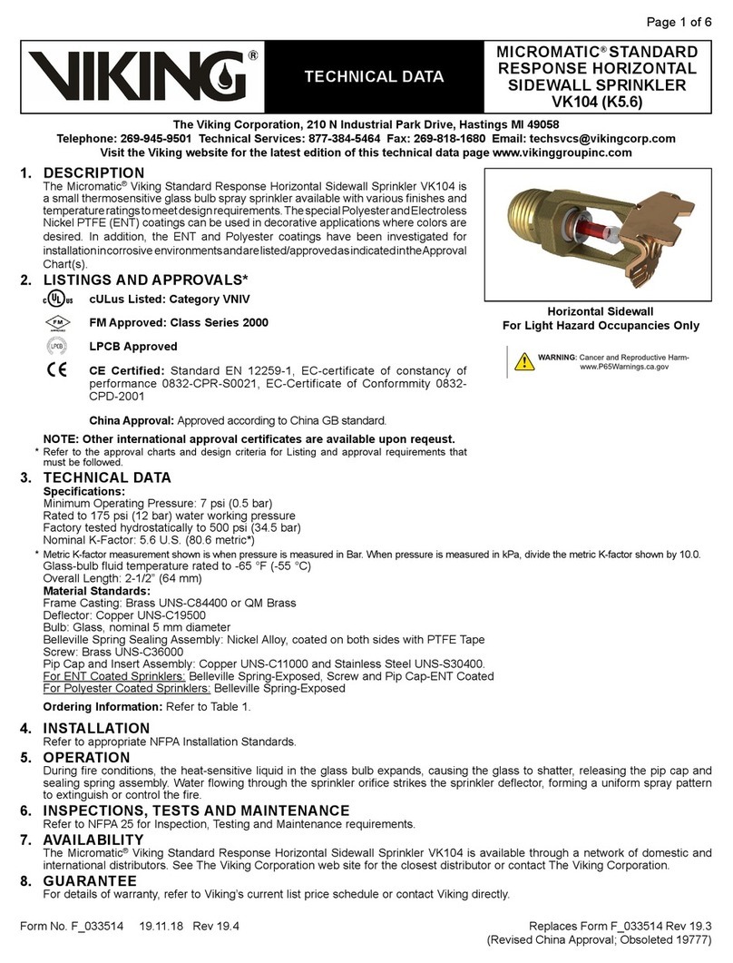
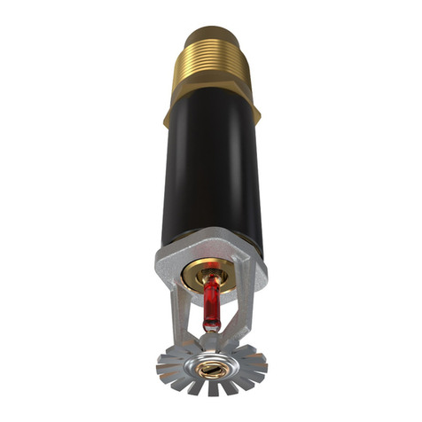
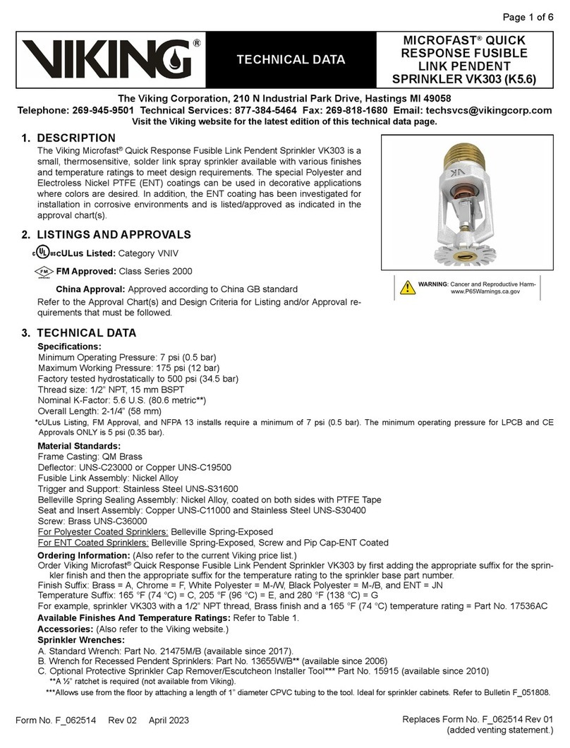
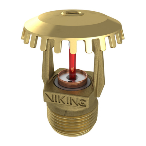
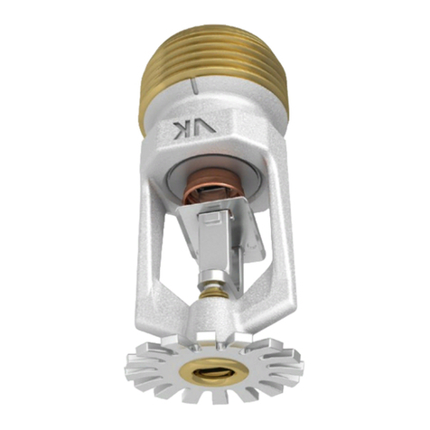
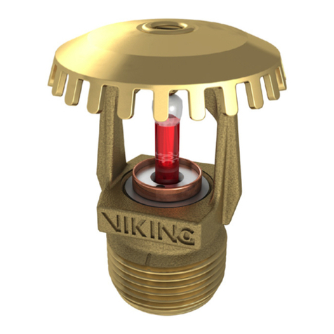
Viking quick response sprinklers are
thermosensitive spray sprinklers con-
sisting of a small frame and either a
glass bulb or a fusible operating ele-
ment that meets the criteria for quick
response. Available styles include pen-
dent, flush pendent, concealed pendent,
concealed sidewall, upright, horizontal
sidewall, flush horizontal sidewall, verti-
cal sidewall, or conventional (old style).
Quick response sprinklers are avail-
able with various finishes, temperature
ratings, and K-Factors to meet design
requirements†.
† Refer to the appropriate sprinkler technical
data page for available styles, finishes,
temperature ratings, and nominal K-Factors
for specific sprinkler models.
4. TECHNICAL DATA
Refer to the appropriate sprinkler tech-
nical data page for listing and approval
information and technical information on
sprinkler materials and accessories.
5. CARE AND HANDLING
(Also refer to Bulletin - Care and Handling of
Sprinklers, Form No. F_091699.)
Sprinklers must be handled with care.
They must be stored in a cool, dry
place in their original shipping container.
Never install sprinklers that have been
dropped, damaged, or exposed to tem-
peratures exceeding the maximum am-
bient temperature allowed. Never install
any glass-bulb sprinkler if the bulb is
cracked or if there is a loss of liquid from
the bulb. Any sprinkler with a loss of
liquid from the glass bulb or damage to
the fusible element should be destroyed
immediately.
Sprinklers must be protected from me-
chanical damage. Sprinklers subject to
mechanical damage must be protected
with an approved sprinkler guard.
Use only sprinklers listed as corrosion
resistant when subject to corrosive en-
vironments. When installing corrosion-
resistant sprinklers, take care not to
damage the corrosion-resistant coating.
appropriate sprinkler model and style,
with the correct orifice size, temperature
rating, and response characteristics.
Sprinklers must be installed after the
piping is in place to prevent mechanical
damage. Keep sprinklers with protective
caps or bulb shields contained within
the caps or shields during installation
and testing, and any time the sprinkler
is shipped or handled.
A1. For frame-style sprinklers, install es-
cutcheon (if used), which is designed
to thread onto the external threads of
the sprinkler.*
Refer to the appropriate sprinkler data page
to determine approved escutcheons.
A2. For quick response flush and
concealed style sprinklers: Cut the
sprinkler nipple so that the ½” or 3/4”
(15 mm or 20 mm)** NPT outlet of the
reducing coupling is at the desired lo-
cation, and centered in the opening**
in the ceiling or wall.
**Size depends on the sprinkler model used.
Refer to appropriate sprinkler data page.
B. Apply a small amount of pipe-joint
compound or tape to the external
threads of the sprinkler only, taking
care not to allow a build-up of com-
pound in the sprinkler inlet.
NOTE: Sprinklers with protective caps or
bulb shields must be contained within
thecapsorshieldsbeforeapplyingpipe-
joint compound or tape. Exception: For
concealed sprinklers VK302, VK352,
VK462, VK463, and VK464, remove
the protective cap for installation.
C. Refer to the appropriate sprinkler
technical data page to determine the
correct sprinkler wrench for the model
of sprinkler used. DO NOT use the
deflector or fusible element to start or
thread the sprinkler into a fitting.
Install the sprinkler onto the piping
using the special sprinkler wrench
only, taking care not to over-tighten or
damage the sprinkler operating parts.
Forflushandconcealedstylesprin-
klers: the internal diameter of the
special sprinkler installation wrench
is designed for use with the sprinkler
contained within the protective shell.
Exception: For concealed sprinklers
VK302, VK352, VK462, VK463, and
VK464, remove the protective cap for
installation, and then place it back on
the sprinkler temporarily. Thread the
quick response flush or concealed
sprinkler into the ½” or 3/4” (15 mm
or 20 mm)†† NPT outlet of the cou-
pling by turning it clockwise with the
special sprinkler wrench.
††Thread size depends on the particular
*
Note:Unitsofmeasureinparenthesesmaybeapproximations.
Form No. F_011500 Replaces page QR1-2, dated Jan. 16, 2006 (updated for new con-
cealed sprinklers). Refer to the appropriate sprinkler technical
data page for detailed information on specific sprinkler models.
Sprinkler QR1
For Institutional Flush Style
Sprinklers, refer to the appropriate
institutional sprinkler technical data
page for installation instructions.
OBSOLETE
QUICK RESPONSE
SPRINKLERS
GENERAL CARE, INSTALLATION,
AND MAINTENANCE GUIDE
TECHNICAL DATA
May 19, 2006
Sprinkler QR2
Replaces page QR1-2, dated January 16, 2006 (updated for concealed sprinklers). Refer to the
appropriate sprinkler technical data page for detailed information on specific sprinkler models. Form No. F_011500
sprinkler model used. Refer to the appro-
priate sprinkler technical data page.
D. After installation, the entire sprinkler
system must be tested. The test must
be conducted to comply with the in-
stallation standards.
Viking high pressure sprinklers may
be hydrostatically tested at a maxi-
mum of 300 psi (2 069 kPa) for limit-
ed periods of time (two hours), for the
purpose of acceptance by the AHJ.
Make sure the sprinkler is properly
tightened. If a thread leak occurs, nor-
mally the sprinkler must be removed,
new pipe-joint compound or tape ap-
plied, and then reinstalled. This is due
to the fact that when the joint seal is
damaged, the sealing compound or
tape is washed out of the joint.
Air testing [do not exceed 40 psi (276
kPa)] the sprinkler piping prior to
testing with water may be considered
in areas where leakage during test-
ing must be prevented. Refer to the
Installation Standards and the AHJ.
E. Remove plastic protective sprin-
kler caps or bulb shields AFTER
the wall or ceiling finish work is
completed where the sprinkler is
installed and there no longer is a
potentialformechanicaldamageto
the sprinkler operating elements.
To remove the bulb shields, simply
pull the ends of the shields apart
where they are snapped together. To
remove caps from frame style sprin-
klers, turn the caps slightly and pull
them off the sprinklers. SPRINKLER
CAPS OR BULB SHIELDS MUST
BEREMOVEDFROM SPRINKLERS
BEFORE PLACING THE SYSTEM
IN SERVICE! Retain a protective cap
or shield in the spare sprinkler cabinet.
F1. For quick response flush style
sprinklers: the escutcheon ring can
now be installed onto the sprinkler
body. Align the escutcheon ring with
the sprinkler body and thread or
push it on (depends on sprinkler
model) until the outer flange touches
the surface of the ceiling or wall in
which the sprinkler is installed. Note
the maximum adjustment is 1/4” (6,35
mm) for quick response flush pendent
sprinklers and ½” (12,7 mm) for quick
response flush HSW sprinklers. DO
NOT MODIFYTHE UNIT. If necessary,
re-cut the sprinkler nipple as required.
F2. For QR concealed sprinklers:
the cover assembly can now be at-
tached.
Remove the cover from the protec-
tive box, taking care not to damage
When replacing existing sprinklers, the
system must be removed from service.
Refer to the appropriate system descrip-
tion and/or valve instructions. Prior to
removing the system from service, notify
all AHJs. Consideration should be given
to employment of a fire patrol in the af-
fected area.
A. Remove the system from service,
drain all water, and relieve all pres-
sure on the piping.
B. For frame-style sprinklers, use the spe-
cial sprinkler wrench to remove the old
sprinkler by turning it counterclock-
wise to unthread it from the piping.
For quick response flush and con-
cealed style sprinklers: Remove
the escutcheon ring or cover plate
assembly before unthreading the
sprinkler body from the piping.
Escutcheon rings and cover plates
can be removed either by gen-
tly unthreading them or pulling
them off the sprinkler body (de-
pends on the sprinkler model used).
After the escutcheon ring or cover
plate assembly has been removed
from the sprinkler body, place a plastic
shell (from the spare sprinkler cabinet)
over the sprinkler to be removed and
then fit the sprinkler wrench over the
shell.Thenuse thewrench tounthread
the sprinkler from the piping. Exception:
concealed sprinklers VK302, VK352,
VK462, VK463, and VK464 are re-
moved without the plastic cap.
C. Install the new unit by follow-
ing the instructions in section 6.
INSTALLATION. Care must be taken
to ensure that the replacement sprin-
kler is the proper model and style, with
the correct orifice size, temperature
rating, and response characteristics.
A fully stocked spare sprinkler cabinet
should be provided for this purpose.
For flush or concealed sprinklers:
stock of spare ceiling rings or cover
plates should also be available in the
spare sprinkler cabinet.
D. Place the system back in service and
secure all valves. Check for and re-
pair all leaks. Sprinkler systems that
have been subjected to a fire must
be returned to service as soon as
possible. The entire system must be
inspected for damage, and repaired
or replaced as necessary. Sprinklers
that have been exposed to corrosive
products of combustion or high ambi-
ent temperatures, but have not oper-
ated, should be replaced. Refer to
the Authority Having Jurisdiction for
minimum replacement requirements.
the cover plate assembly.
Gently place the base of the cover
plate assembly over the sprinkler pro-
truding through the opening in the
ceiling or wall.
Push the cover plate assembly onto
the sprinkler until the unfinished brass
flange of the cover plate base (or the
cover adapter, if used) touches the
surface of the ceiling or wall.
The maximum adjustment avail-
able for quick response concealed
sprinklers is ½” (12,7 mm). DO NOT
MODIFY THE UNIT. If necessary, re-
cut the sprinkler nipple.
G. If it is necessary to remove the entire
sprinkler unit, the system must be
taken out of service. See section 7.
MAINTENANCE and follow all warn-
ings and instructions.
7. MAINTENANCE
NOTICE: The owner is responsible for
maintaining the fire-protection system
and devices in proper operating condi-
tion. For minimum maintenance and
inspection requirements, refer to the ap-
propriate NFPA standard that describes
care and maintenance of sprinkler sys-
tems. In addition, the AHJ may have ad-
ditional maintenance, testing, and inspec-
tion requirements that must be followed.
Sprinklers must be inspected on a regu-
lar basis for corrosion, mechanical dam-
age, obstructions, paint, etc. The fre-
quency of inspections may vary due to
corrosive atmospheres, water supplies,
and activity around the device.
Sprinklers or cover plate assemblies
that have been painted or mechanically
damaged must be replaced immediately.
Sprinklers showing signs of corrosion
shall be tested and/or replaced immedi-
ately as required. Installation standards
require sprinklers to be tested and, if
necessary, replaced after a specified
term of service. Refer to the installa-
tion standards (e.g., NFPA 25) and the
AHJ for the specified period of time
after which testing and/or replacement
is required. Sprinklers or cover plate
assemblies that have operated cannot
be reassembled or re-used, but must
be replaced. When replacing sprinklers,
use only new sprinklers and cover plate
assemblies.
The sprinkler discharge pattern is criti-
cal for proper fire protection. Therefore,
nothing should be hung from, attached
to, or otherwise obstruct the discharge
pattern.All obstructions must be immedi-
ately removed or, if necessary, additional
sprinklers installed.
OBSOLETE

Other Viking Irrigation System manuals

Viking VK506 Instruction manual

Viking

Viking VK506 Instruction manual

Viking HQR-2 User manual

Viking

Viking HQR-2 User manual

Viking VK3021 Instruction manual

Viking

Viking VK3021 Instruction manual

Viking MICROFAST VK302 Instruction manual

Viking

Viking MICROFAST VK302 Instruction manual

Viking MICROFAST VK3311 Instruction manual

Viking

Viking MICROFAST VK3311 Instruction manual

Viking HORIZON H-3 Instruction manual

Viking

Viking HORIZON H-3 Instruction manual

Viking MICROFAST VK3271 Instruction manual

Viking

Viking MICROFAST VK3271 Instruction manual

Viking FREEDOM VK470 Instruction manual

Viking

Viking FREEDOM VK470 Instruction manual

Viking VK4651 Instruction manual

Viking

Viking VK4651 Instruction manual

Viking MICROFAST VK350 Instruction manual

Viking

Viking MICROFAST VK350 Instruction manual

Viking VK3541 Instruction Manual

Viking

Viking VK3541 Instruction Manual

Viking VK2002 Instruction manual

Viking

Viking VK2002 Instruction manual

Viking VK3542 Instruction manual

Viking

Viking VK3542 Instruction manual

Viking VK512 K25.2 Instruction manual

Viking

Viking VK512 K25.2 Instruction manual

Viking MicrofastHP VK341 Instruction manual

Viking

Viking MicrofastHP VK341 Instruction manual

Viking MICROFAST VK345 Instruction manual

Viking

Viking MICROFAST VK345 Instruction manual

Viking MICROFAST VK326 Instruction manual

Viking

Viking MICROFAST VK326 Instruction manual

Viking V-HIP Instruction manual

Viking

Viking V-HIP Instruction manual

Viking FREEDOM VK4840 Instruction manual

Viking

Viking FREEDOM VK4840 Instruction manual

Viking MICROFAST VK352 Instruction manual

Viking

Viking MICROFAST VK352 Instruction manual

Viking VK4611 Instruction manual

Viking

Viking VK4611 Instruction manual

Viking MICROFAST VK307 Instruction manual

Viking

Viking MICROFAST VK307 Instruction manual

Viking VK502 Instruction manual

Viking

Viking VK502 Instruction manual

Viking FREEDOM VK468 User manual

Viking

Viking FREEDOM VK468 User manual

Popular Irrigation System manuals by other brands

Tyco Fire Product CENTRAL WS instruction manual

Tyco Fire Product

Tyco Fire Product CENTRAL WS instruction manual

Reliable GL112 quick start guide

Reliable

Reliable GL112 quick start guide

IrriGreen Irrigreen2 installation manual

IrriGreen

IrriGreen Irrigreen2 installation manual

Task Force Tips G-Force INSTRUCTIONS FOR SAFE OPERATION AND MAINTENANCE

Task Force Tips

Task Force Tips G-Force INSTRUCTIONS FOR SAFE OPERATION AND MAINTENANCE

Rain Bird RSD-BEx user guide

Rain Bird

Rain Bird RSD-BEx user guide

Bionix Aquabot OtoClear 7270 Instructions for use

Bionix

Bionix Aquabot OtoClear 7270 Instructions for use

Tyco Fire Product TY300-FRB instruction manual

Tyco Fire Product

Tyco Fire Product TY300-FRB instruction manual

Tyco LFII Series quick start guide

Tyco

Tyco LFII Series quick start guide

claber MULTIPLA AC 230/24 V LCD user manual

claber

claber MULTIPLA AC 230/24 V LCD user manual

Fiskars 1027028 Original instructions

Fiskars

Fiskars 1027028 Original instructions

Eden 96214EDAMZ quick start guide

Eden

Eden 96214EDAMZ quick start guide

Tyco ESFR-17 quick start guide

Tyco

Tyco ESFR-17 quick start guide

Tyco CHEC manual

Tyco

Tyco CHEC manual

Tyco TY-QRF-5.6 quick start guide

Tyco

Tyco TY-QRF-5.6 quick start guide

Tyco Fire Protection Products PROTECTOSPRAY EA-1 manual

Tyco Fire Protection Products

Tyco Fire Protection Products PROTECTOSPRAY EA-1 manual

Toro MultiMatrix V-1550 Adjustment instructions

Toro

Toro MultiMatrix V-1550 Adjustment instructions

Tyco Fire Product DS-2 Series instruction manual

Tyco Fire Product

Tyco Fire Product DS-2 Series instruction manual

AQUAJOE AJ-OMS20-BRS user manual

AQUAJOE

AQUAJOE AJ-OMS20-BRS user manual

manuals.online logo
manuals.online logoBrands
  • About & Mission
  • Contact us
  • Privacy Policy
  • Terms and Conditions

Copyright 2025 Manuals.Online. All Rights Reserved.