Installation
PM
TIME
/ CANCEL
-+MODE
ALERT TONES
SINGLE DOUBLE TRIPLE
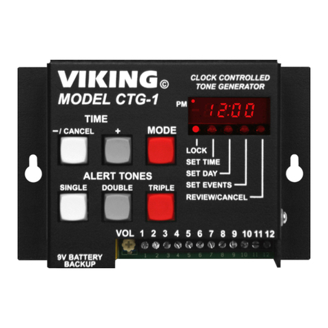
VIKING©
MODEL CTG-1
LOCK
SET TIME
SET EVENTS
REVIEW/CANCEL
CLOCK CONTROLLED
TONE GENERATOR
ALERT TONE
VOLUME
9V BATTERY
BACKUP
12345678910
12:00
Clock, Event Time and Mode Display
Mode Button: Press to place the CTG-1
in the Lock, Set Time, Set Events or
Review/Cancel modes.
Clock and Event Time Setting
Button: Press the +or -/CANCEL
buttons to increase or decrease time.
The -/CANCEL switch is also used to
cancel an alert tone/buzzer sound
event when reviewing programming.
Alert Tones
Programming Buttons: After
setting an event time, press single,
double or triple to program 1, 2 or 3
alert tones/buzzer sounds for that
event time.
9V Battery Backup Connection:
A standard or rechargeable
(NiCad/NiMh) 9V battery must be
installed here to maintain the clock
time during power outages.
CTG-1 Output Volume Control:
Turn clockwise to increase volume of alert
tones/buzzer sounds, emergency and door
bell (chime) sounds (See Diagram 2 below).
*Note: When the alarm buzzer sound is selected (pin 6 shorted to pin 10), a double or triple programmed event will be
sounded twice, approximately three seconds apart.
Detail B
Secondary Relay Contacts: These
activate in conjunction with pins 3, 4 and
5. You may solder to these PCB pads if
a second set of relay contacts are
required.
Battery Charge Shunt:
Note: Factory set default is OFF.
For rechargeable batteries, move the
Battery Charge shunt to the ON
position.
10. Common
9. Emergency Siren (Yelp): Continuous while
shorted to pin 10 (common).
1-2. 600 Ohm Audio Out Pair: Line level output.
Connect to input of paging amplifier.
8. Evacuation Sound (Temporal Slow Whoop):
Continuous while shorted to pin 10 (common).
7. Doorbell Chime Sound (Ding Dong): Repeated
continuously while shorted to pin 10 (common).
6. Alert Tone/Buzzer*: Short to common pin 10
for buzzer sound, leave open for tones.
5. Normally Open Relay Contact
4. Common Relay Connection
3. Normally Closed Relay Contact
A. Typical Installation on the Paging Port of a Phone System
Connect the CTG-1 between your phone system and your paging amplifier as shown in Diagram 2 below. A 9V
battery must be installed in the CTG-1 to maintain clock time during a power outage. Either a standard or
rechargeable 9V battery will maintain the clock time for over 8 hours.
Battery
Charge
ON
OFF
Detail A
Battery
Charge
ON
OFF
J63
1
2
N.O.
Common
N.C.
J63
1
2
Diagram 1
12345678910
115V AC outlet
Common
Volume
control
9V battery
connection
Siren
Evac Signal
Door Bell
Alert tone / buzzer sound select
(open = tones, closed = buzzer sounds)
Paging
output of
PABX/KSU
Dry contact closures from alarm
equipment, door bell switch, etc.
Diagram 2
Note: When using a rechargeable 9 volt battery, the battery charging shunt must be in the ON position (see Detail A
above). When using a non-rechargeable 9 volt battery, this shunt must be in the OFF position.
-or-
Input of Paging Amp
