manuals.online logo
Brands
  1. Home
  2. •
  3. Brands
  4. •
  5. Viking
  6. •
  7. Refrigerator
  8. •
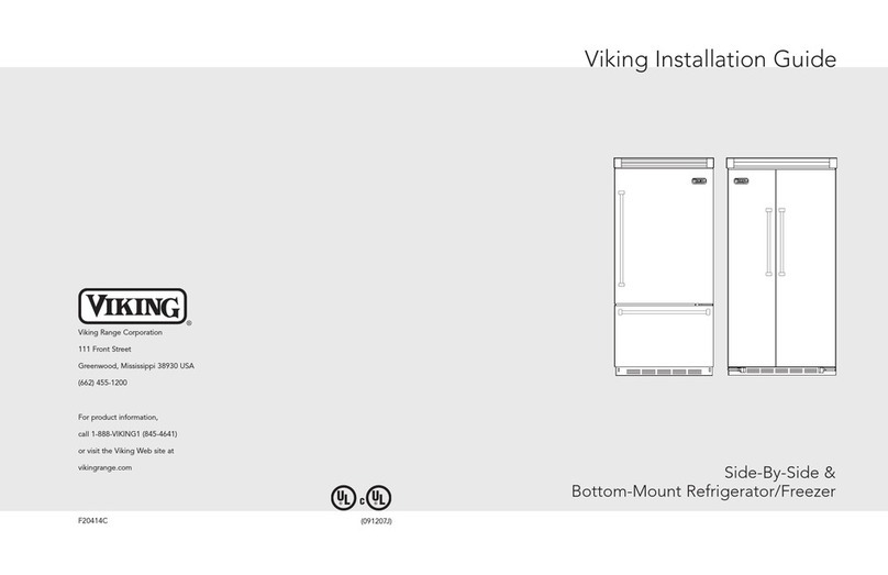
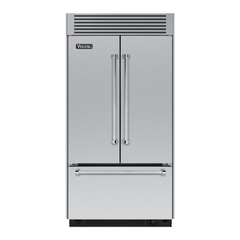
  9. Viking AF/AR User manual

Viking AF/AR User manual

Viking Range Corporation
111 Front Street
Greenwood, Mississippi 38930 USA
(662) 455-1200
For produ t information,
all 1-888-VIKING1 (845-4641)
or visit the Viking Web site at
vikingrange. om
F20416A (071007J)
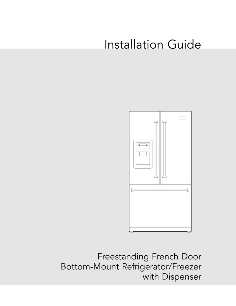
Viking Installation Guide
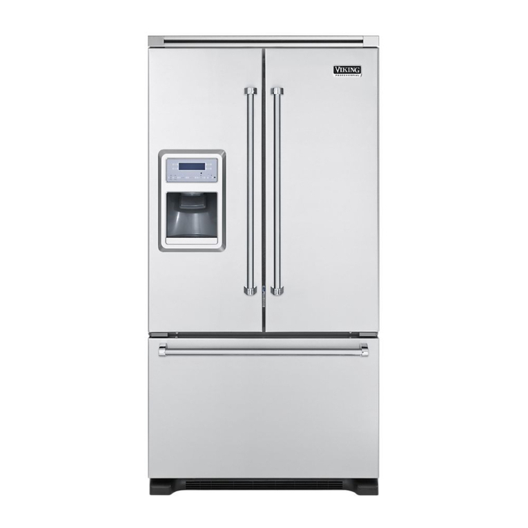
All Refrigerator/Freezer
UL
C
UL
4
Table of Contents IMPORTANT–Please Read and Follow!
•Make sure that in oming voltage is the same
as unit rating. An ele tri rating plate
spe ifying voltage, frequen y, wattage,
amperage, and phase is atta hed to the
produ t.
• To redu e the risk of fire, ele tri sho k, or
injury to persons, installation work and
ele tri al wiring must be done by qualified
people in a ordan e with all appli able
odes and standards, in luding fire-rated
onstru tion.
• The installer should leave these instru tions
with the onsumer who should retain them
for lo al inspe tor’s use and for future
referen e.
It is your responsibility to:
• Comply with installation spe ifi ations and
dimensions
• Properly install unit
• Remove any moldings or de orative panels
that prevent the unit from being servi ed
• Make sure that you have these materials (not
provided with your unit), whi h are ne essary
for proper installation:
•1/4” (6 mm) opper tubing with shutoff
valve
•6– #8 x 3” (7.6 m) wood s rews (longer
s rews may be required)
•1– Saddle valve (do not use self-pier ing
feature of the valve)
• Assure that floor will support unit, door
panels and ontents (approximately 1200
pounds [540 kg])
• Provide a properly grounded ele tri al outlet
• Assure that lo ation will permit applian e
doors to open 90˚ minimum
WARNING
TIP OVER HAZARD
Applian e is top
heavy and tips easily
when not ompletely
installed. Keep doors
losed until applian e
is ompletely installed
and se ured per installation instru tions.
Use two or more people to move and
install applian e. Failure to do so an
result in death or serious injury.
WARNING
ELECTRICAL SHOCK
HAZARD
Dis onne t power or turn
power dis onne t swit h to
OFF position before removing
top grille. Failure to do so an
result in death or ele tri al sho k.
Your safety and the safety of others is
very important.
We have provided many important safety
messages in this manual and on your
applian e. Always read and obey all
safety messages.
This is the safety alert symbol. This
symbol alerts you to hazards that
an kill or hurt you and others.
All safety messages will be pre eded by the
safety alert symbol and the word“DANGER”
or “WARNING.”These words mean:
D A N G E R
You will be killed or seriously injured if
you don’t follow instructions.
WARNING
You can be killed or seriously injured if
you don’t follow instructions.
All safety messages will identify the
hazard, tell you how to redu e the han e
of injury, and tell you what an happen if
the instru tions are not followed.
Most of the unit’s weight is at the top. Extra are is needed when moving the unit to prevent
tipping. Use ardboard shipping material or plywood under unit until it is installed in the
operating position to prote t floor surfa e.
Warnings & Important Information
_________________________________________________________
4
Professional
Dimensions (30” and 36”)________________________________________________________ 5
Spe ifi ations (30” and 36”)______________________________________________________ 6
Cutout Dimensions (30”)_________________________________________________________ 7
Anti-Tip Dimensions (30”) ________________________________________________________ 8
Cutout Dimensions (36”) _________________________________________________________ 9
Anti-Tip Dimensions (36”) _______________________________________________________ 10
Dimensions (Dual 30”) __________________________________________________________ 11
Dimensions (Dual 30” and 36”) ____________________________________________________ 12
Dimensions (Dual 36”) ____________________________________________________________ 13
Spe ifi ations (Dual)_____________________________________________________________ 14
Cutout Dimensions (Dual 30”)____________________________________________________ 15
Anti-Tip Dimensions (Dual 30”) ___________________________________________________ 16
Cutout Dimensions (Dual 30” and 36”) ____________________________________________ 17
Cutout Dimensions (Dual 30” and 36”) ____________________________________________ 18
Cutout Dimensions (Dual 36”) ____________________________________________________ 19
Anti-Tip Dimensions (Dual 36”) ___________________________________________________20
Cabinet Information _____________________________________________________________ 21
Designer
Dimensions (30”and 36”) ________________________________________________________ 23
Spe ifi ations (30” and 36”)______________________________________________________ 24
Cutout Dimensions (30”)_________________________________________________________ 25
Anti-Tip (30”)___________________________________________________________________ 26
Cutout Dimensions (36”)_________________________________________________________ 27
Anti-Tip Dimensions (36”)________________________________________________________ 28
Dimensions (Dual 30”)___________________________________________________________ 29
Dimensions (Dual 30” and 36”) ___________________________________________________ 30
Dimensions (Dual 36”)___________________________________________________________ 31
Spe ifi ations (Dual)_____________________________________________________________ 32
Cutout Dimensions (Dual 30”) ____________________________________________________ 33
Anti-Tip Dimensions (Dual 30”) ___________________________________________________ 34
Cutout Dimensions (Dual 30” and 36”) ____________________________________________ 35
Anti-Tip Dimensions (Dual 30” and 36”) ___________________________________________ 36
Cutout Dimensions (Dual 36”) ____________________________________________________ 37
Anti-Tip Dimensions (Dual 36”) ___________________________________________________ 38
Cabinet Information _____________________________________________________________ 39
General Information ________________________________________________________________ 41
Unpa king & Moving _______________________________________________________________ 43
Installation_________________________________________________________________________ 44
Hinge Adjustment __________________________________________________________________ 45
Ki kplate Installation _______________________________________________________________ 47
Door Stop Adjustment ______________________________________________________________ 48
Final Installation ____________________________________________________________________ 48
Performan e Che klist ______________________________________________________________ 50
Control Panels _____________________________________________________________________ 51
Servi e & Registration_______________________________________________________________ 52
6
24–11/16”
(62.7 cm)
35–1/2”
(90.2 cm)
35”
(88.9 cm)
75–15/16”
(192.9 cm)
3–19/32”
(9.1cm)
)
36”
(91.5cm)
27–1/4”
(69.2 cm)
9–5/32”
(23.3 cm)
82–7/8”
(210.5 cm)
Min
to
84–1/16”
(213.5 cm)
Max
20–3/4”
(52.7 cm)
22–3/16”
(56.4 cm)
24–11/16”
(62.7 cm)
29–1/2”
(74.9cm)
29”
(73.7 cm)
75–15/16”
(192.9cm)
3–19/32”
(9.1cm)
30”
(76.2cm)
9–5/32”
(23.3 cm)
82–7/8”
(210.5 cm)
Min
to
84–1/16”
(213.5 cm)
Max
20–3/4”
(52.7 cm)
22–3/16”
(56.4 cm)
27–1/4”
(69.2 cm)
Dimensions (Professional All Refrigerator/Freezer)
5
30” Professional
36” Professional
Spe ifi ations (Professional All Refrigerator/Freezer)
30” All Refrigerator/Freezer
Descri tion VCFB304 VCRB304
Overall Width 30” (76.2 m)
Overall Height from Bottom Min. 82 3/4” (210.2 m) to Max. 84 1/16” (213.5 m)
Overall Depth from Rear To front edge of side trim: 22 3/16” (56.4 m)
To front of top grille: 24 11/16” (62.7 m)
To front of handle end ap: 27 1/4” (69.2 m))
Cutout Width 29 1/2” (74.9 m)
Cutout Height Min. 82 7/8” (210.5 m) to Max. 84 1/16” (213.5 m)
Cutout Depth Min.24” (61.0 m)
Ele tri al Requirements 115 volt, 60 Hz, 15 amp dedi ated ir uit; 3-wire ord with
grounded 3-prong plug atta hed to produ t
Maximum Amp Usage 9.9 amps
Inlet Water 1/4” opper tubing inlet
Requirements waterline; minimum 20 psi; N/A
maximum 120 psi
Overall Interior Dimensions
Total Capa ity 15.9 u. ft. (450 liters) 18.2 u. ft. (516 liters)
Approximate Shipping Weight 425 lbs. (193.2 kg)
36” All Refrigerator/Freezer
Descri tion VCFB364 VCRB364
Overall Width 36” (91.5 m)
Overall Height from Bottom Min. 82 3/4” (210.2 m) to Max. 84 1/16” (213.5 m)
Overall Depth from Rear To front edge of side trim: 22 3/16” (56.4 m)
To front of top grille: 24 11/16” (62.7 m)
To front of handle end ap: 27 1/4” (69.2 m)
Cutout Width 35 1/2” (90.2 m)
Cutout Height Min. 82 7/8” (210.5 m) to Max. 84 1/16” (213.5 m)
Cutout Depth Min. 24” (61.0 m)
Ele tri al Requirements 115 volt, 60 Hz, 15 amp dedi ated ir uit; 3-wire ord with
grounded 3-prong plug atta hed to produ t
Maximum Amp Usage 9.9 amps
Inlet Water 1/4” opper tubing inlet
Requirements waterline; minimum 20 psi; N/A
maximum 120 psi
Overall Interior Dimensions
Total Capa ity 19.1 u. ft. (541 liters) 22.8 u. ft. (646 liters)
Approximate Shipping Weight 500 lbs. (227.3 kg)
Two 2”x 4” Mounting Boards
3” (7.6 cm) x 3 1/2” (8.9 cm)
Note: If unit is installed deeper than 24”(61.0 cm), then shim
behind the mountingboards by the difference.
Bottom of anti-tip board is 3–7/8” (9.8 cm) below opening height.
Note: Top of unit must be placedfirmly under anti-tip board.
Anti-Tip Location
79–3/8”
(201.6 cm)min
to bottomof
anti-tipboard
80–1/2”
(204.6 cm) max
to bottomof
anti-tipboard
23”
(58.4 cm)
3–1/2”
(8.9 cm)
3”
(7.6 cm)
Anti-Tip Dimensions (Professional All Refrigerator/Freezer)
8
9”
(22.9cm)
73 3/8”
(186.4 cm)
82–7/8”
(210.5 cm)min
anti-tip board&
opening height
84–1/16”
(213.5cm)min
anti-tip board&
opening height
29–1/2”
(74.9 cm)
24”
(61.0 cm)
Electric Outlet Location
Water Line Entry Area
Note: Shown for All Freezer Only
29–1/2”
(74.9 cm)
6–3/4”
(17.1 cm)
7–5/8”
(19.4 cm)
3”
(7.6 cm)
5/8”
(1.5 cm)
5/8”
(1.5 cm)
10–1/2”
(26.7 cm)
5/8”
(1.5 cm)
10–3/4”
(27.3 cm)
1”
(2.5cm)
3–5/8”
(9.2 cm)
Optional floor
water line entry
SeeAnti-Tip boardinstallation
6”
(15.2cm)
9”
(22.9cm)
Cutout Dimensions (Professional All Refrigerator/Freezer)
7
30” Professional 30” Professional
Two 2”x 4” Mounting Boards
3” (7.6 cm) x 3 1/2” (8.9 cm)
Note: If unit is installed deeper than 24”(61.0 cm), then shim
behind the mountingboards by the difference.
Bottom of anti-tip board is3–7/8” (9.8 cm) below opening height.
Note: Top of unit must be placedfirmly under anti-tip board.
Anti-Tip Location
79–3/8”
(201.6 cm)min
to bottomof
anti-tipboard
80–1/2”
(204.6 cm) max
to bottomof
anti-tipboard
29–1/2”
(74.9 cm)
3–1/2”
(8.9 cm)
3”
(7.6 cm)
Anti-Tip Dimensions (Professional All Refrigerator/Freezer)
10
9”
(22.9cm)
73 3/8”
(186.4 cm)
82–7/8”
(210.5 cm)min
anti-tip board&
opening height
84–1/16”
(213.5cm)min
anti-tip board&
opening height
35–1/2”
(90.2 cm)
24”
(61.0 cm)
Electric Outlet Location
Water Line Entry Area
Note: Shown for All Freezer Only
35–1/2”
(90.2 cm)
6–3/4”
(17.1 cm)
7–5/8”
(19.4 cm)
3”
(7.6 cm)
5/8”
(1.5 cm)
5/8”
(1.5 cm)
10–1/2”
(26.7 cm)
5/8”
(1.5 cm)
10–3/4”
(27.3 cm)
1”
(2.5cm)
3–5/8”
(9.2 cm)
Optional floor
water line entry
SeeAnti-Tip boardinstallation
6”
(15.2cm)
9”
(22.9cm)
Cutout Dimensions (Professional All Refrigerator/Freezer)
9
36” Professional 36” Professional
24–11/16”
(62.7 cm)
35–1/2”
(90.2 cm)
1”
(2.54 cm)
Between Units
35”
(88.9 cm)
36”
(91.5 cm)
9–5/32”
(23.3cm)
82–7/8”
(210.5 cm)
Min
to
84–1/16”
(213.5cm)
Max
20–3/4”
(52.7 cm)
22–3/16”
(56.4 cm)
29–1/2”
(74.9 cm)
29”
(73.7 cm)
75–15/16”
(192 .9 cm)
3–19/32”
(9.1cm)
30”
(76.2 cm)
27–1/4”
(69.2cm)
Dimensions (Professional All Refrigerator/Freezer)
12
24–11/16”
(62.7 cm)
1”
(2.54 cm)
Between Units
9–5/32”
(23.3 cm)
82–7/8”
(210.5cm)
Min
to
84–1/16”
(213.5cm)
Max
20–3/4”
(52.7 cm)
22–3/16”
(56.4 cm)
29–1/2”
(74.9 cm)
29–1/2”
(74.9 cm)
75–15/16”
(192.9cm)
3–19/32”
(9.1cm)
29”
(73.7 cm)29”
(73.7 cm)
30”
(76.2 cm)
30”
(76.2 cm)
27–1/4”
(69.2cm)
Dimensions (Professional All Refrigerator/Freezer)
11
Dual 30” Professional Dual 30” and 36” Professional
Spe ifi ations (Professional All Refrigerator/Freezer)
14
24–11/16”
(62.7 cm)
35–1/2”
(90.2 cm)
1”
(2.54 cm)
Between Units
35”
(88.9cm)
35”
(88.9cm)
36”
(91.5 cm)
36”
(91.5cm)
9–5/32”
(23.3 cm)
82–7/8”
(210.5 cm)
Min
to
84–1/16”
(213.5 cm)
Max
20–3/4”
(52.7 cm)
22–3/16”
(56.4 cm)
35–1/2”
(90.2 cm)
75–15/16”
(192 .9 cm)
3–19/32”
(9.1 cm)
27–1/4”
(69.2cm)
Dimensions (Professional All Refrigerator/Freezer)
13
Dual 36” Professional Dual All Refrigerator/Freezer
Descri tion (2) 30” Units (1) 36” & (1) 30” Unit (2) 36” Units
Overall Width 60” (152.4 m) 66” (167.6 m) 72” (182.9 m)
Overall Height from Bottom Min. 82 3/4” (210.2 m) to Max. 84 1/16” (213.5 m)
Overall Depth from Rear To front edge of side trim: 22 3/16” (56.4 m)
To front of top grille: 24 11/16” (62.7 m)
To front of handle end ap: 27 1/4” (69.2 m)
Cutout Width 59 1/2” (151.1 m) 65 1/2” (166.4 m) 71 1/2” (181.6 m)
Cutout Height Min. 82 7/8” (210.5 m) to Max. 84 1/16” (213.5 m)
Cutout Depth Min. 24” (61.0 m)
Ele tri al Requirements (2) 115 volt, 60 Hz, 15 amp dedi ated ir uit; 3-wire ord with
grounded 3-prong plug atta hed to produ t
Maximum Amp Usage 9.9 amps per unit
Inlet Water Requirements 1/4” opper tubing inlet waterline; minimum 20 psi;
(All Freezer Only) maximum 120 psi
Overall Interior Dimensions
30” Freezer 15.9 u. ft. (450 liters)
30” Refrigerator 18.2 u. ft. (516 liters)
36” Freezer 19.1 u. ft. (541 liters)
36” Refrigerator 22.8 u. ft. (646 liters)
Approximate Shipping Weight 30” Freezer or Refrigerator 425 lbs. (193.2 kg)
36” Freezer or Refrigerator 500 lbs. (227.3 kg)
79–3/8”
(201.6 cm)min
to bottomof
anti-tipboard
80–1/2”
(204.6 cm) max
to bottomof
anti-tipboard
Two 2”x 4” Mounting Boards Per Unit
3” (7.6 cm) x 3 1/2” (8.9 cm)
Note: If unit is installed deeper than 24” (61.0 cm), then shim
behind the anti-tip bracket by the difference.
Bottom of anti-tip board is3–7/8” (9.8 cm) below opening height.
Note: Top of unit must be placedfirmly under anti-tip board.
Anti-Tip Location
23”
(58.4 cm)
3–1/2”
(8.9 cm)
3”
(7.6 cm)
23”
(58.4 cm)
Anti-Tip Dimensions (Professional All Refrigerator/Freezer)
16
9”
(22.9 cm)
733/8”
(186.4 cm)
82–7/8”
(210.5 cm) min
anti-tip board&
openingheight
84–1/16”
(213.5cm) min
anti-tipboard&
opening height
59–1/2”
(151.1 cm)
24”
(61.0 cm)
Electric Outlet Location
Water Line Entry Area
Note: Cutout opening shown with All Freezermodel on left.
Reverse waterline entry if All Freezer model is on right.
59–1/2”
(151.1cm)
6–3/4”
(17.1cm)
7–5/8”
(19.4cm)
3”
(7.6 cm)
5/8”
(1.5 cm)
5/8”
(1.5cm)
10–1/2”
(26.7cm)
5/8”
(1.5cm)
10–3/4”
(27.3 cm)
3–5/8”
(9.2 cm)
Optional floor
water lineentry
1”
(2.5cm)
SeeAnti-Tip boardinstallation
6”
(15.2cm)
9”
(22.9cm)
Cutout Dimensions (Professional All Refrigerator/Freezer)
15
Dual 30” Professional Dual 30” Professional
79–3/8”
(201.6 cm)min
to bottomof
anti-tipboard
80–1/2”
(204.6 cm) max
to bottomof
anti-tipboard
Two 2”x 4” Mounting Boards Per Unit
3” (7.6 cm) x 3 1/2” (8.9 cm)
Note: If unit is installed deeper than 24” (61.0 cm), then shim
behind the mountingboards by the difference.
Bottom of anti-tip board is3–7/8” (9.8 cm) below opening height.
Note: Top of unit must be placedfirmly under anti-tip board.
Note: Dimensions shown for 36”AF/AR model on the left.
Reverse mounting boards if units are installed on the right.
Anti-Tip Location
29”
(73.7 cm)
3–1/2”
(8.9 cm)
3”
(7.6 cm)
23”
(58.4 cm)
Anti-Tip Dimensions (Professional All Refrigerator/Freezer)
18
9”
(22.9 cm)
733/8”
(186.4 cm)
82–7/8”
(210.5 cm) min
anti-tip board&
openingheight
84–1/16”
(213.5cm) min
anti-tipboard&
opening height
65–1/2”
(166.4 cm)
24”
(61.0 cm)
Electric Outlet Location
Water Line Entry Area
Note: Cutout opening shown with All Freezer model on left.
Reverse water line entry if All Freezer model is on right.
65–1/2”
(166.4cm)
6–3/4”
(17.1cm)
7–5/8”
(19.4cm)
3”
(7.6 cm)
5/8”
(1.5 cm)
5/8”
(1.5cm)
10–1/2”
(26.7cm)
5/8”
(1.5cm)
10–3/4”
(27.3 cm)
3–5/8”
(9.2 cm)
Optional floor
water lineentry
1”
(2.5cm)
SeeAnti-Tip boardinstallation
6”
(15.2cm)
9”
(22.9cm)
Cutout Dimensions (Professional All Refrigerator/Freezer)
17
Dual 30” and 36” Professional
79–3/8”
(201.6 cm)min
to bottomof
anti-tipboard
80–1/2”
(204.6 cm) max
to bottomof
anti-tipboard
Two 2”x 4” Mounting Boards Per Unit
3” (7.6 cm) x 3 1/2” (8.9 cm)
Note: If unit is installed deeper than 24” (61.0 cm), then shim
behind the mountingboards by the difference.
Bottom of anti-tip board is3–7/8” (9.8 cm) below opening height.
Note: Top of unit must be placedfirmly under anti-tip board.
Anti-Tip Location
29”
(73.7 cm)
3–1/2”
(8.9 cm)
3”
(7.6 cm)
29”
(73.7 cm)
Anti-Tip Dimensions (Professional All Refrigerator/Freezer)
20
9”
(22.9 cm)
733/8”
(186.4 cm)
82–7/8”
(210.5 cm) min
anti-tip board&
openingheight
84–1/16”
(213.5cm) min
anti-tipboard&
opening height
71–1/2”
(181.6 cm)
24”
(61.0 cm)
Electric Outlet Location
Water Line Entry Area
Note: Cutout opening shown with All Freezermodel on left.
Reverse waterline entry if All Freezer model is on right.
71–1/2”
(181.6cm)
6–3/4”
(17.1cm)
7–5/8”
(19.4cm)
3”
(7.6cm)
5/8”
(1.5 cm)
5/8”
(1.5cm)
10–1/2”
(26.7cm)
5/8”
(1.5cm)
10–3/4”
(27.3 cm)
3–5/8”
(9.2 cm)
Optional floor
waterlineentry
1”
(2.5cm)
SeeAnti-Tip boardinstallation
6”
(15.2cm)
9”
(22.9cm)
Cutout Dimensions (Professional All Refrigerator/Freezer)
19
Dual 36” Professional Dual 36” Professional
Top View
1–13/16”
(4.6 cm)
Space if 24”
standard
cabinet
depth is
used
Door
24”
(61.0 cm)
Standard
Cabinet
Depth
Wall
3/4”
(1.9 cm)
Full End
Panel
2–1/2”
(6.4 cm) Offset
Partial Overlay
Cabinet Door
Cabinet Information (Professional)
22
Top View
Top View
1–13/16”
(4.6 cm)
Space if 24”
standard
cabinet
depth is
used
Door
24”
(61.0 cm)
Standard
Cabinet
Depth
Wall
3/4”
(1.9 cm)
Full End
Panel
2–1/2”
(6.4 cm) Offset
Countertop
Overhang
Door
Wall
1–13/16”
(4.6 cm)
Space if 24”
standard
cabinet
depth is
used
3/4”
(1.9 cm)
Full End
Panel
24”
(61.0 cm)
Standard
Cabinet
Depth
2–1/2”
(6.4 cm) Offset
5–16”
(0.8 cm)
Cabinet Information (Professional)
21
Professional models fit “semi-flush” in standard 24” (61.0 m) deep abinet openings. The door
fa e protrudes 2-1/2” (6.4 m) from the abinet fa e. The handle protrudes an additional
2-1/2” (6.4 m) into the room.
Professional models fit “semi-flush” in standard 24” (61.0 m) deep abinet openings. The door
fa e protrudes 2-1/2” (6.4 m) from the abinet fa e. The handle protrudes an additional
2-1/2” (6.4 m) into the room.
Spe ifi ations (Designer All Refrigerator/Freezer)
24
24”
(61.0 cm)
36”
(91.5 cm)
35”
(88.9 cm)
75–15/16”
(192.9 cm)
3–1/2”
(8.9cm
)
9–5/32”
(23.3 cm)
82–7/8”
(210.5 cm)
Min
to
84–1/16”
(213.5 cm)
Max
20–3/4”
(52.7 cm)
23–13/16”
(60.5 cm)
24”
(61.0 cm)
30”
(76.2 cm)
29”
(73.7 cm)
75–15/16”
(192.9cm)
3–1/2”
(8.9cm)
9–5/32”
(23.3 cm)
82–7/8”
(210.5 cm)
Min
to
84–1/16”
(213.5 cm)
Max
20–3/4”
(52.7 cm)
23–13/16”
(60.5 cm)
26”
(66.0cm)
26”
(66.0 cm)
Dimensions (Designer All Refrigerator/Freezer)
23
30” Designer
36” Designer
30” All Refrigerator/Freezer
Descri tion DDFB304 DDRB304
Overall Width 30” (76.2 m)
Overall Height from Bottom Min. 82 3/4” (210.2 m) to Max. 84 1/16” (213.5 m)
Overall Depth from Rear To front edge of side trim: 23 13/16” (60.5 m)
To front of top grille: 24” (61.0 m)
To front of handle: 26” (66.0 m)
Cutout Width 30” (76.2 m)
Cutout Height Min. 82 7/8” (210.5 m) to Max. 84 1/16” (213.5 m)
Cutout Depth Min. 24” (61.0 m)
Ele tri al Requirements 115 volt, 60 Hz, 15 amp dedi ated ir uit; 3-wire ord with
grounded 3-prong plug atta hed to produ t
Maximum Amp Usage 9.9 amps
Inlet Water 1/4” opper tubing inlet
Requirements waterline; minimum 20 psi; N/A
maximum 120 psi
Overall Interior Dimensions
Total Capa ity 15.9 u. ft. (450 liters) 18.2 u. ft. (516 liters)
Approximate Shipping Weight 425 lbs. (193.2 kg)
36” All Refrigerator/Freezer
Descri tion DDFB364 DDRB364
Overall Width 36” (91.5 m)
Overall Height from Bottom Min. 82 3/4” (210.2 m) to Max. 84 1/16” (213.5 m)
Overall Depth from Rear To front edge of side trim: 23 13/16” (60.5 m)
To front of top grille: 24” (61.0 m)
To front of handle: 26” (66.0 m)
Cutout Width 36” (91.5 m)
Cutout Height Min. 82 7/8” (210.5 m) to Max. 84 1/16” (213.5 m)
Cutout Depth Min. 24” (61.0 m)
Ele tri al Requirements 115 volt, 60 Hz, 15 amp dedi ated ir uit; 3-wire ord with
grounded 3-prong plug atta hed to produ t
Maximum Amp Usage 9.9 amps
Inlet Water 1/4” opper tubing inlet
Requirements waterline; minimum 20 psi; N/A
maximum 120 psi
Overall Interior Dimensions
Total Capa ity 19.1 u. ft. (541 liters) 22.8 u. ft. (646 liters)
Approximate Shipping Weight 500 lbs. (227.3 kg)
One 2”x 4” Mounting Board
1–1/2” (3.8 cm) x 3 1/2” (8.9 cm)
Note: If unit is installed deeper than 24”(61.0 cm), then shim
behind the mountingboards by the difference.
Bottom of anti-tip board is3–7/8” (9.8 cm) below opening height.
Note: Top of unit must be placedfirmly under anti-tip board.
Anti-Tip Location
79–3/8”
(201.6 cm)min
to bottomof
anti-tipboard
80–1/2”
(204.6 cm) max
to bottomof
anti-tipboard
23”
(58.4 cm)
3–1/2”
(8.9 cm)
1 1/2”
(3.8 cm)
Anti-Tip Dimensions (Designer All Refrigerator/Freezer)
26
9”
(22.9cm)
73 3/8”
(186.4 cm)
82–7/8”
(210.5 cm)min
anti-tip board&
opening height
84–1/16”
(213.5cm)min
anti-tip board&
opening height
30”
(76.2 cm)
24”
(61.0 cm)
Electric Outlet Location
Water Line Entry Area
Note: Shown for All Freezer Only
30”
(76.2 cm)
6–3/4”
(17.1 cm)
7–5/8”
(19.4 cm)
3”
(7.6 cm)
5/8”
(1.5 cm)
5/8”
(1.5 cm)
10–1/2”
(26.7 cm)
5/8”
(1.5 cm)
10–3/4”
(27.3 cm)
1”
(2.5cm)
3–5/8”
(9.2 cm)
Optional floor
water line entry
SeeAnti-Tip boardinstallation
6”
(15.2cm)
9”
(22.9cm)
Cutout Dimensions (Designer All Refrigerator/Freezer)
25
30” Designer 30” Designer
One 2”x 4” Mounting Board
1–1/2” (3.8 cm) x 3 1/2” (8.9 cm)
Note: If unit is installed deeper than 24” (61.0 cm), then shim
behind the mountingboards by the difference.
Bottom of anti-tip board is3–7/8” (9.8 cm) below opening height.
Note: Top of unit must be placedfirmly under anti-tip board.
Anti-Tip Location
79–3/8”
(201.6 cm)min
to bottomof
anti-tipboard
80–1/2”
(204.6 cm) max
to bottomof
anti-tipboard
29”
(73.7 cm)
3–1/2”
(8.9 cm)
1 1/2”
(3.8 cm)
Anti-Tip Dimensions (Designer All Refrigerator/Freezer)
28
9”
(22.9cm)
73 3/8”
(186.4 cm)
82–7/8”
(210.5 cm)min
anti-tip board&
opening height
84–1/16”
(213.5cm)min
anti-tip board&
opening height
36”
(91.5 cm)
24”
(61.0 cm)
Electric Outlet Location
Water Line Entry Area
Note: Shown for All Freezer Only
36”
(91.5 cm)
6–3/4”
(17.1 cm)
7–5/8”
(19.4 cm)
3”
(7.6 cm)
5/8”
(1.5 cm)
5/8”
(1.5 cm)
10–1/2”
(26.7 cm)
5/8”
(1.5 cm)
10–3/4”
(27.3 cm)
1”
(2.5cm)
3–5/8”
(9.2 cm)
Optional floor
water line entry
SeeAnti-Tip boardinstallation
6”
(15.2cm)
9”
(22.9cm)
Cutout Dimensions (Designer All Refrigerator/Freezer)
27
36” Designer 36” Designer
24”
(61.0 cm)
36”
(91.5 cm)
1”
(2.54 cm)
Between Units
35”
(88.9 cm)
9–5/32”
(23.3cm)
82–7/8”
(210.5 cm)
Min
to
84–1/16”
(213.5cm)
Max
20–3/4”
(52.7cm)
23–13/16”
(56.4 cm)
30”
(76.2 cm)
29”
(73.7 cm)
75–15/16”
(192 .9 cm)
3–1/2”
(8.9cm)
26”
(66.0cm)
Dimensions (Designer All Refrigerator/Freezer)
30
24”
(66.0 cm)
1”
(2.54 cm)
Between Units
9–5/32”
(23.3 cm)
82–7/8”
(210.5cm)
Min
to
84–1/16”
(213.5cm)
Max
20–3/4”
(52.7 cm)
23–13/16”
(60.5 cm)
30”
(76.2 cm)
30”
(76.2 cm)
75–15/16”
(192.9cm)
3–1/2”
(8.9cm)
29”
(73.7 cm)29”
(73.7 cm)
26”
(66.0 cm)
Dimensions (Designer All Refrigerator/Freezer)
29
Dual 30” Designer Dual 30” and 36” Designer
Spe ifi ations (Designer All Refrigerator/Freezer)
32
24”
(61.0 cm)
36”
(91.4 cm)
1”
(2.54 cm)
Between Units
35”
(88.9cm)
35”
(88.9cm)
9–5/32”
(23.3 cm)
82–7/8”
(210.5 cm)
Min
to
84–1/16”
(213.5 cm)
Max
20–3/4”
(52.7 cm)
23–13/16”
(60.5 cm)
36”
(91.4 cm)
75–15/16”
(192 .9 cm)
3–1/2”
(8.9 cm)
26”
(66.0 cm)
Dimensions (Designer All Refrigerator/Freezer)
31
Dual 36” Designer Dual All Refrigerator/Freezer
Descri tion (2) 30” Units (1) 36” & (1) 30” Unit (2) 36” Units
Overall Width 60” (152.4 m) 66” (167.6 m) 72” (182.9 m)
Overall Height from Bottom Min. 82 3/4” (210.2 m) to Max. 84 1/16” (213.5 m)
Overall Depth from Rear To front edge of side trim: 23 13/16” (60.5 m)
To front of top grille: 24” (61.0 m)
To front of handle: 26” (66.0 m)
Cutout Width 60” (152.4 m) 66” (167.6 m) 72” (182.9 m)
Cutout Height Min. 82 7/8” (210.5 m) to Max. 84 1/16” (213.5 m)
Cutout Depth Min. 24” (61.0 m)
Ele tri al Requirements (2) 115 volt, 60 Hz, 15 amp dedi ated ir uit; 3-wire ord with
grounded 3-prong plug atta hed to produ t
Maximum Amp Usage 9.9 amps per unit
Inlet Water Requirements 1/4” opper tubing inlet waterline; minimum 20 psi;
(All Freezer Only) maximum 120 psi
Overall Interior Dimensions
30” Freezer 15.9 u. ft. (450 liters)
30” Refrigerator 18.2 u. ft. (516 liters)
36” Freezer 19.1 u. ft. (541 liters)
36” Refrigerator 22.8 u. ft. (646 liters)
Approximate Shipping Weight 30” Freezer or Refrigerator 425 lbs. (193.2 kg)
36” Freezer or Refrigerator 500 lbs. (227.3 kg)
79–3/8”
(201.6 cm)min
to bottomof
anti-tipboard
80–1/2”
(204.6 cm) max
to bottomof
anti-tipboard
One 2”x 4” Mounting BoardPer Unit
1–1/2” (3.8 cm) x 3 1/2” (8.9 cm)
Note: If unit is installed deeper than 24” (61.0 cm), then shim
behind the mountingboards by the difference.
Bottom of anti-tip board is 3–7/8” (9.8 cm) below opening height.
Note: Top of unit must be placedfirmly under anti-tip board.
Anti-Tip Location
23”
(58.4 cm)
3–1/2”
(8.9 cm)
1 1/2”
(3.8 cm)
23”
(58.4 cm)
Anti-Tip Dimensions (Designer All Refrigerator/Freezer)
34
9”
(22.9 cm)
733/8”
(186.4 cm)
82–7/8”
(210.5 cm) min
anti-tip board&
openingheight
84–1/16”
(213.5cm) min
anti-tipboard&
opening height
60”
(152.4 cm)
24”
(61.0 cm)
Electric Outlet Location
Water Line Entry Area
Note: Cutout opening shown with All Freezermodel on left.
Reverse waterline entry if All Freezer model is on right.
60”
(152.4cm)
6–3/4”
(17.1cm)
7–5/8”
(19.4cm)
3”
(7.6cm)
5/8”
(1.5 cm)
5/8”
(1.5cm)
10–1/2”
(26.7cm)
5/8”
(1.5cm)
10–3/4”
(27.3 cm)
3–5/8”
(9.2 cm)
Optional floor
waterlineentry
1”
(2.5cm)
SeeAnti-Tip boardinstallation
6”
(15.2cm)
9”
(22.9cm)
Cutout Dimensions (Designer All Refrigerator/Freezer)
33
Dual 30” Designer Dual 30” Designer
79–3/8”
(201.6 cm)min
to bottomof
anti-tipboard
80–1/2”
(204.6 cm) max
to bottomof
anti-tipboard
One 2”x 4” Mounting BoardPer Unit
1–1/2” (3.8 cm) x 3 1/2” (8.9 cm)
Note: If unit is installed deeper than 24” (61.0 cm), then shim
behind the mountingboards by the difference.
Bottom of anti-tip board is 3–7/8” (9.8 cm) below opening height.
Note: Top of unit must be placedfirmly under anti-tip board.
Note: Dimensions shown for 36”AF/AR model on the left.
Reverse mounting boards if units are installed on the right.
Anti-Tip Location
29”
(73.7 cm)
3–1/2”
(8.9 cm)
1 1/2”
(3.8 cm)
23”
(58.4 cm)
Anti-Tip Dimensions (Designer All Refrigerator/Freezer)
36
9”
(22.9 cm)
733/8”
(186.4 cm)
82–7/8”
(210.5 cm) min
anti-tip board&
openingheight
84–1/16”
(213.5cm) min
anti-tipboard&
opening height
66”
(167.6 cm)
24”
(61.0 cm)
Electric Outlet Location
Water Line Entry Area
Note: Cutout opening shown with All Freezermodel on left.
Reverse waterline entry if All Freezer model is on right.
66”
(167.6cm)
6–3/4”
(17.1cm)
7–5/8”
(19.4cm)
3”
(7.6 cm)
5/8”
(1.5 cm)
5/8”
(1.5cm)
10–1/2”
(26.7cm)
5/8”
(1.5cm)
10–3/4”
(27.3 cm)
3–5/8”
(9.2 cm)
Optional floor
waterlineentry
1”
(2.5cm)
SeeAnti-Tip boardinstallation
6”
(15.2cm)
9”
(22.9cm)
Cutout Dimensions (Designer All Refrigerator/Freezer)
35
Dual 30” and 36” Designer Dual 30” and 36” Designer
79–3/8”
(201.6 cm)min
to bottomof
anti-tipboard
80–1/2”
(204.6 cm) max
to bottomof
anti-tipboard
One 2”x 4” Mounting BoardPer Unit
1–1/2” (3.8 cm) x 3 1/2” (8.9 cm)
Note: If unit is installed deeper than 24” (61.0 cm), then shim
behind the mountingboards by the difference.
Bottom of anti-tip board is3–7/8” (9.8 cm) below opening height.
Note: Top of unit must be placedfirmly under anti-tip board.
Anti-Tip Location
29”
(73.7 cm)
3–1/2”
(8.9 cm)
1 1/2”
(3.8 cm)
29”
(73.7 cm)
Anti-Tip Dimensions (Designer All Refrigerator/Freezer)
38
9”
(22.9 cm)
733/8”
(186.4 cm)
82–7/8”
(210.5 cm) min
anti-tip board&
openingheight
84–1/16”
(213.5cm) min
anti-tipboard &
opening height
72”
(182.9 cm)
24”
(61.0 cm)
Electric Outlet Location
Water Line Entry Area
Note: Cutout opening shown with All Freezermodel on left.
Reverse waterline entry if All Freezer model is on right.
72”
(182.9cm)
6–3/4”
(17.1cm)
7–5/8”
(19.4cm)
3”
(7.6 cm)
5/8”
(1.5 cm)
5/8”
(1.5cm)
10–1/2”
(26.7cm)
5/8”
(1.5cm)
10–3/4”
(27.3 cm)
3–5/8”
(9.2 cm)
Optional floor
waterlineentry
1”
(2.5cm)
SeeAnti-Tip boardinstallation
6”
(15.2cm)
9”
(22.9cm)
Cutout Dimensions (Designer All Refrigerator/Freezer)
37
Dual 36” Designer Dual 36” Designer
Top View
Overlapping cabinet doors
Top View
Flush mount cabinet doors
Door
24”
(61.0cm)
Standard
Cabinet
Depth
24-3/4”
(62.9 cm)
Wall
3/4”
(1.9 cm)
Full End
Panel
1”
(2.5 cm)
If standard
25” (63.5 cm)
standard
cabinet depth
is used
Flush
Cabinet
Door
Door
Wall
3/4”
(1.9 cm)
Full End
Panel
1”
(2.5 cm)
If standard
25” (63.5 cm)
standard
cabinet depth
is used
Flush
25”
(63.5 cm)
Cabinet
Depth
Cabinet
Door
Cabinet Information (Designer)
40
Top View
Top View
Door
24”
(61.0 cm)
Standard
Cabinet
Depth
25”
(63.5 cm)
Countertop
Depth
Wall
3/4”
(1.9 cm)
Full End
Panel
Door
Wall
1”
(2.5 cm)
If standard
25” (63.5 cm)
standard
cabinet depth
is used
3/4”
(1.9 cm)
Full End
Panel
25”
(63.5 cm)
Flush
1”
(2.5 cm)
If standard
25” (63.5 cm)
standard
cabinet depth
is used
Flush
Cabinet Information (Designer)
39
Designer models fit flush in standard 24” (61.0 m) deep abinet openings with no protrusion into the
room ex ept 2”(5.1 m) urved handle depth.
Designer models fit flush in standard 24” (61.0 m) deep abinet openings with no protrusion into the
room ex ept 2”(5.1 m) urved handle depth.

This manual suits for next models

4

Other Viking Refrigerator manuals

Viking Professional VCBB363 User manual

Viking

Viking Professional VCBB363 User manual

Viking VRUO5240 User manual

Viking

Viking VRUO5240 User manual

Viking Bottom-Mount User manual

Viking

Viking Bottom-Mount User manual

Viking F20603D User manual

Viking

Viking F20603D User manual

Viking VCFF136D User manual

Viking

Viking VCFF136D User manual

Viking RDDFF236SS User manual

Viking

Viking RDDFF236SS User manual

Viking DDBF036* User manual

Viking

Viking DDBF036* User manual

Viking F20603 User manual

Viking

Viking F20603 User manual

Viking Professional VISB548BR User manual

Viking

Viking Professional VISB548BR User manual

Viking DFFB304 User guide

Viking

Viking DFFB304 User guide

Viking VUWC140 Service manual

Viking

Viking VUWC140 Service manual

Viking Quiet Cool VCRB5301 User manual

Viking

Viking Quiet Cool VCRB5301 User manual

Viking VCSB5482 User manual

Viking

Viking VCSB5482 User manual

Viking Designer DDFF136DSS User manual

Viking

Viking Designer DDFF136DSS User manual

Viking CVRI7240 User manual

Viking

Viking CVRI7240 User manual

Viking Designer DFRD144D Technical manual

Viking

Viking Designer DFRD144D Technical manual

Viking VCBB5363E User manual

Viking

Viking VCBB5363E User manual

Viking Freestanding User manual

Viking

Viking Freestanding User manual

Viking RDFN536D User manual

Viking

Viking RDFN536D User manual

Viking Designer DFBB363 User manual

Viking

Viking Designer DFBB363 User manual

Viking Quiet Cool FDBB5361R Assembly instructions

Viking

Viking Quiet Cool FDBB5361R Assembly instructions

Viking D3 RDFN536D User manual

Viking

Viking D3 RDFN536D User manual

Viking Designer DDFF136SS User manual

Viking

Viking Designer DDFF136SS User manual

Viking VURE524G User manual

Viking

Viking VURE524G User manual

Popular Refrigerator manuals by other brands

LabRepCo LABH?14?SD owner's guide

LabRepCo

LabRepCo LABH?14?SD owner's guide

LG LRBP1031W Service manual

LG

LG LRBP1031W Service manual

Kenmore 795.5137 Use and care guide

Kenmore

Kenmore 795.5137 Use and care guide

Indesit CTAA 55 NF UK Instructions for installation and use

Indesit

Indesit CTAA 55 NF UK Instructions for installation and use

Whirlpool AFB 828 Instructions for use

Whirlpool

Whirlpool AFB 828 Instructions for use

Bosch KIV34A21FF Instructions for use

Bosch

Bosch KIV34A21FF Instructions for use

KitchenAid KUIS18NNZB Limited warranty

KitchenAid

KitchenAid KUIS18NNZB Limited warranty

Hotpoint HTJ18GCTSA Dimensions and installation information

Hotpoint

Hotpoint HTJ18GCTSA Dimensions and installation information

Kenmore 106.5116 Use & care guide

Kenmore

Kenmore 106.5116 Use & care guide

Indel Webasto Marine Isoterm Drawer Inox Series Installation and usage instructions

Indel Webasto Marine

Indel Webasto Marine Isoterm Drawer Inox Series Installation and usage instructions

Beko CBI 7702 manual

Beko

Beko CBI 7702 manual

Electrolux IK 2700 Z RE user manual

Electrolux

Electrolux IK 2700 Z RE user manual

CASTOR CF315B2 Instruction book

CASTOR

CASTOR CF315B2 Instruction book

GE Profile CustomStyle PSC23SHTSS Dimension Guide

GE

GE Profile CustomStyle PSC23SHTSS Dimension Guide

Gram FB Instructions for use

Gram

Gram FB Instructions for use

Westinghouse WTB2300PA user manual

Westinghouse

Westinghouse WTB2300PA user manual

Hotpoint HSS22GFT Dimension Guide

Hotpoint

Hotpoint HSS22GFT Dimension Guide

RCA RFR551 instruction manual

RCA

RCA RFR551 instruction manual

manuals.online logo
manuals.online logoBrands
  • About & Mission
  • Contact us
  • Privacy Policy
  • Terms and Conditions

Copyright 2025 Manuals.Online. All Rights Reserved.