Vimar Plana User manual
Viale Vicenza, 14 - I 36063 Marostica VI
Tel. +39 0424 488 600 - Fax (Italia) +39 0424 488 188 - Fax (Export) +39 0424 488 709
www.vimar.eu
Istruzioni
Instruction sheet
Notice technique
90714635 0C 0803
VIMAR - Marostica - Italy
Plana
14635
14636
Description
14635: Support orientable pour appareil 1 module
14636: Support orientable pour appareil 2 modules
Cette notice technique contient les instructions pour
l’installation des supports orientables 14635 et 14636
et des accessoires suivants:
•14637:adapteurpourlafixationdessupports
orientables aux supports de montage Plana
•16831.01:cadrepourmontageensailliedes
supports orientables
•16897.S:dispositifsanti-vandale
Les supports orientables permettent l’installation
d’encastrement (en boîtes rectangulaires 3 modules ou
en boîtes rondes ø 60 mm) ou en saillie des détecteurs de
présence 14484 pour systèmes d’alarme et de
l’interrupteur à infrarouge pour allumage de l’éclairage
14180.
Utilisés dans systèmes d’alarme avec le kit 16897.S, ils
assurent la protection anti-vandale et anti-arrachage.
Les appareils doivent être utilisés dans locaux secs
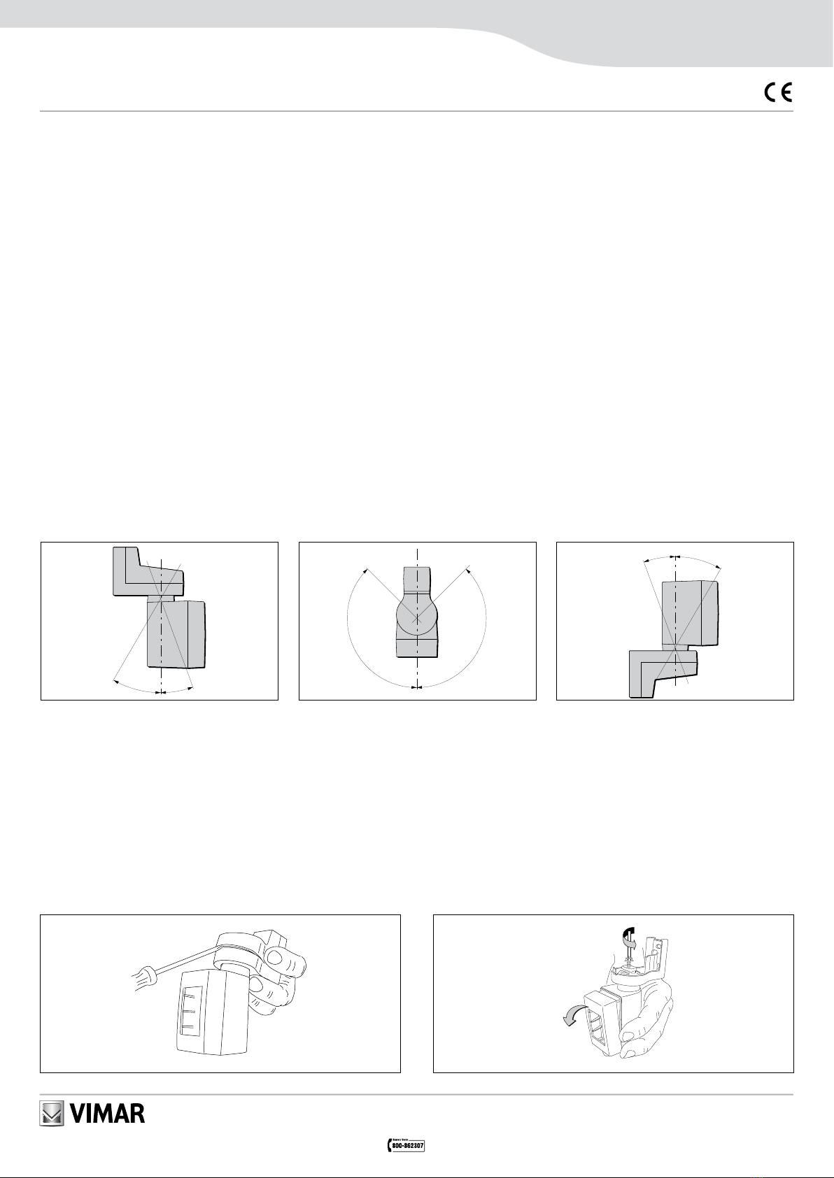
Possibilité d’orientation
Ils peuvent être orientés verticalement ou horizontale-
ment,commeindiquérespectivementàlafigure1et
àlafigure2.
Si le cas, ils peuvent être orientés même renversé
(figure3).
Seréféreràlanoticetechniquedel’appareilutilisépour
les champs de détection.
Description
14635: Orientablesupportingframeforequipments
1 module
14636: Orientablesupportingframeforequipments
2 modules
Thisinstructionsheetprovidesmountinginstructionsof
the orientable supports 14635 and 14636 and of the
followingaccessories:
•14637:adaptorforthefixingoftheorientable
supportsonPlanasupportingframes
•16831.01:frameforthesurfacemountingofthe
orientable supports
•16897.S:setofaccessoriesfortamperproofuse
Theorientablesupportsallowtheflushinstallation
(on 3-module rectangular mounting boxes or ø 60 mm
roundboxes)oronframeforthesurfacemountingof
presencedetectors14484forburglaralarmsystems,or
ofautomaticlightingswitchIRmotionsensor14180.
Used in burglar alarm systems with the kit 16897.S,
theyguaranteetamperproofuseandprotection
against unauthorized removal.
The equipment shall be used in dry location.
Possibilities of orientation
May be either vertically or horizontally oriented
(seerespectivelyfigure1andfigure2).
Ifnecessary,theyarealsopossibletoinstallthem
upsidedown(seefigure3).
Forthedetectionranges,refertotheinstructionsheetof
the installed equipment.
Regole di installazione
L’installazione deve essere effettuata in conformità alle
norme CEI vigenti.
Prima di operare sull’impianto togliere tensione agendo
sull’interruttore generale.
Installazione
1Aprire il coperchio superiore
2Allentarelavitedibloccodellosnodofinoaliberareil
coperchio porta apparecchio
Installation rules
The installation must be done according to in force
ItalianCEIspecifications(orequivalentrulesforelectrical
installationsofbuildings).
Disconnect the mains acting on the main switch
beforeoperatingonthesystem.
Installation
1Open the upper cover
2Unscrew the screw blocking the joint until
the cover designed to acco-
modate the equipment is released
Règles d’installation
L’installationdoitêtreeffectuéeselonlesnormes
italiennes CEI en vigueur (ou normes équivalentes
pour les installations électriques des bâtiments).
Couper l’alimentation en agissant sur l’interrupteur
général avant d’intervenir sur l’installation.
Installation
1Ouvrir le couvercle supérieur
2Dévisser la vis qui bloque le joint jusqu’au déga
gement du porte-appareil
1
2
Descrizione
14635: Supporto orientabile per apparecchi 1 modulo
14636: Supporto orientabile per apparecchi 2 moduli
Sono indicate di seguito le modalità di installazione
dei supporti orientabili 14635 e 14636 e dei seguenti
accessori:
•14637:adattatoreperl’agganciodeisupporti
orientabili su supporti Plana
•16831.01:corniceperfissaggiodeisupporti
orientabili a parete
•16897.S:kitantitamper
I supporti orientabili consentono l’installazione ad incasso
(in scatole rettangolari o rotonde ø 60 mm) o a parete
di rivelatori di presenza per impianti d’allarme 14484 o
dell’interruttore con sensore di presenza ad infrarossi per
accensione luci 14180.
Seutilizzatiinimpiantiantifurtoconappositokit16897.
S garantiscono la protezione contro l’apertura e la
rimozione.
Apparecchi da utilizzare in luoghi asciutti.
Orientabilità
Verticalmentecomeindicatoinfigura1eorizzontalmen-
tecomeindicatoinfigura2.
Se necessario possono essere installati anche capovolti
(figura3).
Per la copertura volumetrica vedere il foglio istruzioni
dell’apparecchio utilizzato.
30
20
1
135
135
2
20
30
3

1 (14484)
1448514180
linea antitamper
Tamperproof line
ligne anti-vandale
linea bus
bus line
ligne bus
L
CARICO
CHARGE
CHARGE
N
3
4
2
1
2
5
67 (14484) 8
Modalità d’installazione da incasso
1 Agganciare l’adattatore 14637 al supporto Plana e,
soloper14484,lastaffaantimanomissioneinclusa
nel kit 16897.S
2 Fissare il supporto Plana alla scatola da incasso,
montarelaplaccaefissareilsupportoorientabile
con le viti in dotazione
3 Cablare il rivelatore e, solo per 14484 la scheda
microswitch inclusa nel kit 16897.S (24 V 1 A)
4 Agganciare il rivelatore al coperchio porta
apparecchio del supporto orientabile
5 Agganciare corpo e coperchio del supporto orientabi-
le
6 Orientare il rivelatore nella posizione desiderata,
quindifissarelavitedibloccodellosnodo
7 Infilareedagganciarelaschedamicroswitchnel
coperchio superiore del supporto orientabile (solo
per 14484)
8 Agganciare il coperchio superiore del supporto
Flush installation modality
1 Fix the adaptor 14637 to the Plana supporting
frameand,onlyfor14484thestirrupfor
tamperproofuseincludedin16897.S
2 FixthePlanasupportingframetotheflush
mountingbox,applythecoverplateandfixthe
orientable support using the delivered screws
3 Connect to the line the microswitch card (24 V 1 A)
includedin16897.Sonlyfor14484
4 Fix the detector to the cover designed to
accomodate the equipment
5 Fixthebodyandcoveroftheorientablesupport
6 Orientthedetectorasdesiredandfastenthescrew
blocking the joint
7 Insertandfixthemicroswitchcard-insidethe
upper coveroftheorientablesupport,
onlyfor14484
8 Fixtheuppercoveroftheorientablesupport
Conduite d’installation d’encastrement
1 Fixer l’adaptateur 14637 au support de montage
Plana et seulement pour 16934 et 16620 le
dispositifanti-vandaleinclusdans16897.S
2 Fixer le support de montage Plana à la boîte de
montage d’encastrement, appliquer la plaque de
recouvrementetfixerlesupportorientableavec
les vis livrées
3 Connecter en série à la ligne la carte microswitch
(24 V 1 A) incluse dans 16897.S seulement pour
14484
4 Fixer le détecteur au porte-appareil du support
orientable
5 Fixer corps et porte-appareil du support orientable
6 Orienter le détecteur comme désiré et visser la vis
qui bloque le joint
7 Inséreretfixerlacartemicroswitchdanslecouvercle
supérieur du support orientable, seulement pour
14484
8 Fixer le couvercle supérieur du support orientable
Surface installation modality
1Fixthebaseofframe16831.01tothewall
2Fixtheframe16831.01toitsbase
3Fix the orientable support using the delivered screw
Conduite d’installation en saillie
1Fixer la base du cadre 16831.01 à la parois
2Fixer le cadre à la base
3Fixer le support orientable avec la vis livrée
40 Tassello per protezione
contro la rimozione
Dowel against
unauthorized
removal
Cheville
anti-arrachage
60
= =
1 2
Modalità d’installazione da parete
1 Fissare la base della cornice 16831.01 alla parete
2 Agganciare la cornice alla base
3 Fissare il supporto orientabile con la vite in dotazione
Procedere come descritto nell’installazione
da incasso (3-8)
Proceed as describe in the flush installation
modality (3-8)
Procéder comme la conduite d’installation
d’encastrement (3-8)
This manual suits for next models
2
Other Vimar Safety Equipment manuals


