Vintage Air Ford F-100 1967 User manual

an ISO 9001:2015 Registered Company
1967 Ford F-100
Evaporator Kit
(751152)
18865 Goll St. San Antonio, TX 78266
Phone: 800-862-6658
Sales: [email protected]
www.vintageair.com
900194 REV B 09/16/19, PG 1 OF 42

2
www.vintageair.com
900194 REV B 09/16/19, PG 2 OF 42
Cover..................................................................................................................................
Table of Contents.................................................................................................................
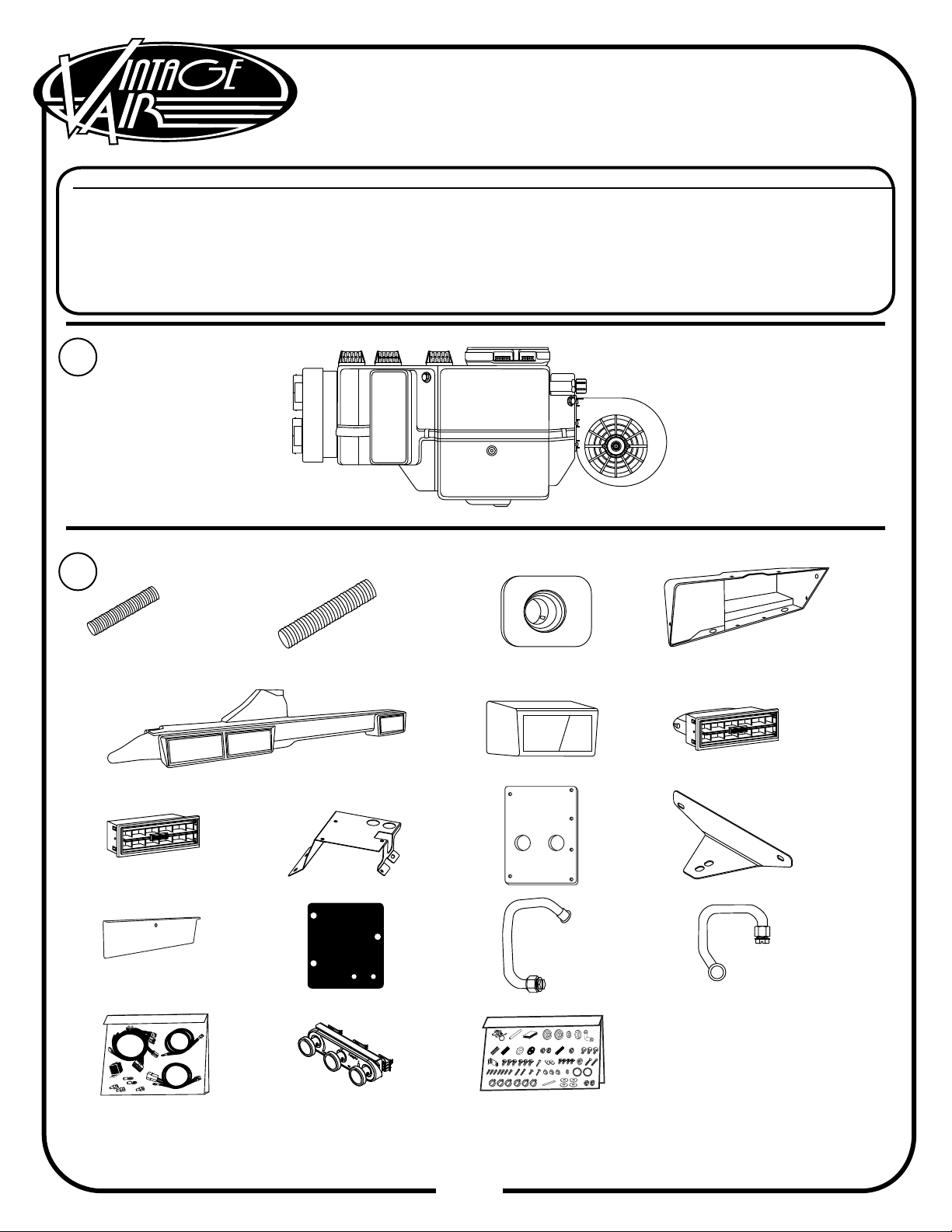
Packing List/Parts Disclaimer..................................................................................................
Information Page..................................................................................................................
Wiring Notice.......................................................................................................................
Engine Compartment Disassembly..........................................................................................
Passenger Compartment Disassembly ....................................................................................
Condenser Assembly and Installation, Compressor and Brackets, Pulleys, Defrost Duct
Installation........................................................................................................................
Passenger Side Wheel Well and Firewall Modication...............................................................
Engine Compartment, Passenger Side Inner Fender Modication...............................................
Firewall Insulation.............................................................................................................
Lubricating O-rings, A/C Hose Routing & Kick Panel Cap Installation..........................................
Wiring Installation..............................................................................................................
Evaporator Firewall Bracket & Heater Hardline Installation.......................................................
Evaporator Installation........................................................................................................
Evaporator Unit Leveling.....................................................................................................
Radio and Control Panel Installation......................................................................................
Radio and Control Panel Installation with Heater Mounted OEM Controls.....................................
Passenger Side Plenum Assembly Louver Bezel Installation......................................................
Duct Hose Installation.........................................................................................................
Driver Side Underdash Louver Installation.............................................................................
Drain Hose Installation........................................................................................................
ECU Wiring Harness Installation...........................................................................................
Glove Box Installation.........................................................................................................
Heater Control Valve Installation..........................................................................................
A/C Hose Installation..........................................................................................................
Wiring Final Steps..............................................................................................................
Final Steps........................................................................................................................
Wiring Diagram..................................................................................................................
Gen IV Wiring Connection Instruction....................................................................................
Operation of Controls..........................................................................................................
Troubleshooting Guide.........................................................................................................
Packing List.......................................................................................................................
1
2
3
4
5
6
7-9
10
11-12
12
13
14-17
17-19
20-21
21-23
24
25
26
27-28
28
29
30
31
32
33
34
35
36
37
38
39
40-41
42
Table of Contents
A detailed tech video outlining the installation process
is available on Vintage Air’s YouTube channel at
http://bit.ly/2kyHG5C.
Viewing the tech video along with the written
instructions will provide the installer the most detailed
installation procedure.

3
www.vintageair.com
900194 REV B 09/16/19, PG 3 OF 42
Packing List:
Evaporator Kit (751152)
No.
1.
2.
Qty.
1
1
Part No.
744019
791152
Description
Gen IV Evaporator Sub Case
Accessory Kit
** Before beginning installation, open all packages and check contents of shipment.
Please report any shortages directly to Vintage Air within 15 days. After 15 days,
Vintage Air will not be responsible for missing or damaged items.
NOTE: Images may not depict actual parts and quantities.
Refer to packing list for actual parts and quantities.
1
2
Gen IV Evaporator
Sub Case
744019
Accessory Kit
791152

4
www.vintageair.com
900194 REV B 09/16/19, PG 4 OF 42
Important Notice—Please Read
For Maximum System Performance, Vintage Air Recommends the Following:
New Vintage Air-supplied Sanden Compressor: No additional oil needed (Compressor is shipped with
proper oil charge).
All Other Compressors: Consult manufacturer (Some compressors are shipped dry and will need oil
added).
NOTE: Vintage Air systems are designed to operate with R134a refrigerant only.
Use of any other refrigerant could damage your A/C system and/or vehicle, and
possibly cause a fire, in addition to potentially voiding the warranties of the A/C
system and its components.
Refrigerant Capacities:
Vintage Air System: 1.8 lbs. (28.8 oz.) or 816 grams of R134a, charged by weight with a quality charging
station or scale. NOTE: Use of the proper type and amount of refrigerant is critical to system
operation and performance.
Other Systems: Consult manufacturer’s guidelines.
Lubricant Capacities:
Safety Switches
Service Info:
Protect Your Investment: Prior to assembly, it is critical that the compressor, evaporator, A/C hoses and
fittings, hardlines, condenser and receiver/drier remained capped. Removing caps prior to assembly will
allow moisture, insects and debris into the components, possibly leading to reduced performance and/or
premature failure of your A/C system. This is especially important with the receiver/drier.
Additionally, when caps are removed for assembly, BE CAREFUL! Some components are shipped under
pressure with dry nitrogen.
Evacuate the System for 35-45 Minutes: Ensure that system components (Drier, compressor, evaporator
and condenser) are at a temperature of at least 85° F. On a cool day, the components can be heated with a
heat gun or by running the engine with the heater on before evacuating. Leak check and charge to
specifications.
Your Vintage Air system is equipped with a binary pressure safety switch. A binary switch disengages the
compressor clutch in cases of extreme low pressure conditions (Refrigerant Loss) or excessively high head
pressure (406 PSI) to prevent compressor damage or hose rupture. A trinary switch combines Hi/Lo
pressure protection with an electric fan operation signal at 254 PSI, and should be substituted for use with
electric fans. Compressor safety switches are extremely important since an A/C system relies on refrigerant
to circulate lubricant.
Bolts Passing Through Cowl and/or Firewall:
To ensure a watertight seal between the passenger compartment and the vehicle exterior, for all bolts
passing through the cowl and/or firewall, Vintage Air recommends coating the threads with silicone prior to
installation.
Heater Hose (Not Included With This Kit):
Heater hose may be purchased from Vintage Air (Part# 31800-VUD) or your local parts retailer. Routing and
required length will vary based on installer preference.

5
www.vintageair.com
900194 REV B 09/16/19, PG 5 OF 42
Important Wiring Notice—Please Read
Some Vehicles May Have Had Some or All of Their Radio Interference Capacitors Removed.
There Should Be a Capacitor Found At Each of the Following Locations:
1. On the positive terminal of the ignition coil.
2. If there is a generator, on the armature terminal of the generator.
3. If there is a generator, on the battery terminal of the voltage regulator.
Most alternators have a capacitor installed internally to eliminate what is called “whining” as
the engine is revved. If whining is heard in the radio, or just to be extra cautious, a radio
interference capacitor can be added to the battery terminal of the alternator.
It is also important that the battery lead is in good shape and that the ground leads are not
compromised. There should be a heavy ground from the battery to the engine block, and
additional grounds to the body and chassis.
If these precautions are not observed, it is possible for voltage spikes to be present on the
battery leads. These spikes come from ignition systems, charging systems, and from
switching some of the vehicle’s other systems on and off. Modern computer-operated
equipment can be sensitive to voltage spikes on the power leads, which can cause unexpected
resets, strange behavior, and/or permanent damage.
Vintage Air strives to harden our products against these types of electrical noise, but there is
a point where a vehicle’s electrical system can be degraded so much that nothing can help.
Radio interference capacitors should be available at most auto and truck parts suppliers. They
typically are cylindrical in shape, a little over an inch long, a little over a half inch in diameter,
and they have a single lead coming from one end of the cylinder with a terminal on the end of
the wire, as well as a mounting clip which is screwed into a good ground on the vehicle. The
specific value of the capacitance is not too significant in comparison to ignition capacitors that
are matched with the coil to reduce pitting of the points.
Care must be taken, when installing the compressor lead, not to short it to ground.
The compressor lead must not be connected to a condenser fan or to any other
auxiliary device. Shorting to ground or connecting to a condenser fan or any other
auxiliary device may damage wiring, the compressor relay, and/or cause a
malfunction.
When installing ground leads on Gen IV systems, the blower control ground and ECU
ground must be connected directly to the negative battery post.
For proper system operation, the heater control valve must be connected to the
ECU.
•
•
•

6
www.vintageair.com
900194 REV B 09/16/19, PG 6 OF 42
Engine Compartment Disassembly
1.
2.
3.
4.
5.
6.
Disconnect the battery.
Place a jack stand under the axle bar on the passenger side of the vehicle (See Photo 1, below), and remove
the passenger side front tire.
Drain the radiator.
Loosen the cable clamp and disconnect the cable from OEM heater control valve (See Photo 2, below).
Disconnect and remove the (2) heater core heater hoses at the rewall, the intake, and the water pump
(discard) (See Photos 3, 4, & 5, below).
From the engine compartment, remove the (3) OEM heater core mounting nuts from the rewall (See Photo
6, below).
NOTE: Before starting the installation, check the function of the vehicle (horn, lights, etc.) for proper
operation, and study the instructions, illustrations, & diagrams. Retain OEM bolts, washers and nuts,
as some hardware will be reused.
Perform the Following:
Photo 1
Place Jack Stand Under Axle Bar
Photo 3
Remove (2) Heater Hoses at Firewall
Photo 5
Remove Heater
Hose at Water Pump
Photo 2
Disconnect Cable Heater Control Valve
Loosen
Cable Clamp
Photo 4
Remove Heater
Hose at Intake
Photo 6
Remove (3) Heater
Core Mounting Nuts
Firewall
Engine Compartment
View
Some F Series trucks are equipped with a 3-speed manual transmission with a “granny” 1st gear. These
congurations use a long shift lever; the most popular in this generation is the 4-speed New Process 435
transmission (Identied as “A” on VIN plate). The shift lever moves approximately 2” further forward
to engage 1st gear compared to 3rd gear. This additional travel may cause an interference with the
underdash louver bezel, and will require a modication to the shift lever in order to clear it.
Important Notice - Please Read

7
www.vintageair.com
900194 REV B 09/16/19, PG 7 OF 42
Passenger Compartment Disassembly
Remove the glove box door by removing the (2) screws on the door hinge and the one screw on the cable
(See Photo 1, below).
Remove the glove box by removing (6) screws (See Photo 2, below).
Remove the glove box by removing the (6) screws around the glove box and (2) glove box door latch screws
(See Photo 2, below). NOTE: The door latch screws must be removed to allow clearance when
installing the new glove box.
Disconnect the cables and wiring from the OEM heater assembly.
Remove the OEM heater assembly by separating the rubber boot from fresh air inlet assembly (discard) (See
Photo 3, below).
Remove the fresh air inlet assembly from the kick panel by removing the (5) OEM screws (See Photo 4,
below).
1.
2.
3.
4.
5.
6.
Photo 2
Photo 4Photo 3
Remove OEM Heater Assembly
Remove (5) OEM Screws
Remove (6) Screws Remove (2) Glove Box
Door Latch Screws
Photo 1
Remove (2) Door
Hinge Screws Remove Cable
Screw
Glove Box Door
Fresh Air Inlet Assembly
Kick Panel

8
www.vintageair.com
900194 REV B 09/16/19, PG 8 OF 42
Photo 5 Photo 6
Photo 7 Photo 8
Passenger Compartment
Disassembly (Cont.)
Disconnect the control panel wiring and plugs.
To remove the heater control switch and pull knobs, perform the following:
A. Remove the fan switch knob by loosening the set screw on the knob shaft (See Photo 5, below).
B. Unscrew the thread adapter counterclockwise and remove (See Photo 6, below).
C. Remove the fan switch bezel (See Photo 6, below), and the rest of the fan switch assembly out from behind
the dash.
D. Remove the remaining (2) pull knobs by unscrewing the (2) jam nuts from the back of the dash (See
Photo 7, below).
E. Remove the bracket (See Photo 7, below), then remove the pull knobs from the front of
the dash (See Photo 8, below).
Disconnect and remove the radio.
7.
8.
9.
Loosen Set Screw Unscrew Thread Adapter and Remove
Remove Fan Switch Bezel
Remove (2) Jam Nuts
Remove Bracket
Remove (2) Pull Knobs

9
www.vintageair.com
900194 REV B 09/16/19, PG 9 OF 42
Disconnect the speedometer cable by loosening the speedometer cable nut and sliding it out of the instrument
cluster (See Photo 9, below).
Remove the (8) instrument cluster bezel mounting screws (retain) (See Photos 10 & 11, below).
Unplug the instrument cluster wiring, and remove the instrument cluster (See Photo 12, below).
Remove the dash pad by removing the (14) dash pad nuts (retain) (See Photo 13, below). NOTE: The
location of the dash pad nuts is shown in Photo 13, below.
Remove the defrost ducts and hoses from the dash defrost outlets.
10.
11.
12.
13.
14.
Disconnect
Speedometer Cable Remove (4) Instrument
Cluster Bezel Screws
Unplug Instrument Cluster Wiring
Location of (14)
Dash Pad Nuts
Dash Pad
Remove (4) Instrument
Cluster Bezel Screws
Passenger Compartment
Disassembly (Final)
Photo 11
Photo 10
Photo 12
Photo 13
Photo 9

10
www.vintageair.com
900194 REV B 09/16/19, PG 10 OF 42
Defrost Duct Installation
1.
2.
3.
4.
5.
6.
Locate the defrost ducts (See Photo 1, below).
Place a defrost duct into each of the dash defrost duct outlets (See Photos 2 & 3, below).
From under the dash, mark the (2) mounting holes onto the defrost ducts.
Remove the defrost ducts, and drill (2) 11/64” holes into each duct (See Figure 1, below).
Install each defrost duct into the dash defrost duct outlet, and secure them using (2) #8 x 1/2” pan head
screws (See Photo 5, below).
Reinstall the dash pad at this time.
Defrost Duct
491655
Photo 1 Photo 3
Place Defrost Duct
into Dash Opening
Photo 2
Defrost Duct
Outlets
Mark and Drill
(2) 11/64” Holes
Figure 1 Photo 4
Place the Defrost Duct into
Dash Defrost Duct Outlet
Photo 5
(2) #8 x 1/2”
Pan Head Screws
Condenser Assembly and Installation
1.
2. Refer to separate instructions included with the condenser kit to install the condenser.
Binary switch installation (Refer to condenser instructions).
Compressor and Brackets
1. Refer to separate instructions included with the bracket kit to install the compressor bracket.
Pulleys
1. In most instances, the belt lengths will remain the same.

11
www.vintageair.com
900194 REV B 09/16/19, PG 11 OF 42
Passenger Side Wheel Well
and Firewall Modication
1.
2.
3.
4.
5.
6.
Remove the passenger side inner fender kick panel grommet (discard) (See Photo 1, below).
Center the rewall A/C hose cover plate onto the passenger side inner fender kick panel opening. Using the
cover plate as a template, mark and drill (2) 5/32” holes (See Photo 2, below).
Measure and mark the rewall insulation as shown in Photo 3, below. NOTE: The measurement starts at
the kick panel and runs along the section where the rewall meets the oorboard.
Remove the measured section of insulation from the rewall, and clean the area (See Photo 4, below).
Remove the OEM rewall insulation retainer (See Photo 5, below).
Enlarge the OEM rewall insulation retainer hole to 5/8” (See Photo 6, below).
Passenger Side Inner Fender
Kick Panel Grommet Mark and Drill
(2) 5/32” Holes
Photo 1 Photo 2
Firewall A/C Hose Cover Plate
646954
Photo 3
Enlarge Hole to 5/8”
Remove OEM Firewall
Insulation Retainer
Photo 5 Photo 6
Passenger Side
Photo 4
26”
20”
6”
Mark and Measure
Firewall Insulation Remove Insulation
and Clean Area

12
www.vintageair.com
900194 REV B 09/16/19, PG 12 OF 42
Engine Compartment, Passenger
Side Inner Fender Modication
1.
2.
On the passenger side inner fender under the battery tray, locate the OEM hole (See Photo 1, below). Enlarge
the hole to 7/8” to accommodate the #10 A/C hose bulkhead tting (See Photo 2, below).
Directly under the recently enlarged hole, in the middle of indented section of the inner fender, mark and drill
a 9/32” hole for the compressor lead grommet (See Photo 3, below).
Photo 1 Photo 2
Photo 3
OEM Hole Under
Battery Tray
Enlarge
Hole to 7/8”
Mark and Drill
9/32” Hole
Battery Tray
Enlarged
7/8” Hole
Indented Section
Passenger Side Wheel Well
and Firewall Modication (Cont.)
7.
8.
Using the heater line opening closest to the passenger side for reference, mark and drill a 1 ¼” hole directly
under the heater line hole on the beveled ledge (See Photos 7 & 8, below). NOTE: Do not enlarge the hole
more than 1 ¼” for the grommet installation.
Install a 1/2” ID x 1 ¼” OD grommet into the 1 ¼” hole (See Photo 9, below).
Drill a 1 ¼” Hole 1/2” ID x 1 ¼” OD Grommet
Beveled Ledge
Photo 7
Heater Line Hole
Mark
Photo 8 Photo 9

13
www.vintageair.com
900194 REV B 09/16/19, PG 13 OF 42
NOTE: For proper operation of the evaporator unit, Vintage Air recommends using heat-blocking
insulation in the area around the subcase (rewall, inner cowl and kick panel). Due to tight clearance
for the evaporator unit between the rewall and dash, Vintage Air recommends an insulation thickness
of no more than 1/4”.
Firewall Insulation
Locate the evaporator rewall bracket as shown in Photo 1, below. Place the evaporator rewall bracket onto
the rewall, and trace around the base of the bracket as shown in Photos 2, 3, and 4, below.
Using spray adhesive, install the new heat-blocking insulation in the area of the rewall that was removed,
being careful not to cover the marked area from the evaporator bracket base and the 1/2” ID x 1 ¼” OD
grommet (See Photos 5 & 6, below). NOTE: During the evaporator installation, if the evaporator unit
does not t properly, look for places where the insulation may be interfering with the evaporator
clearance. Trim the insulation as needed.
1.
2.
Photo 1 Photo 2
Photo 3
Temporarily Install
Evaporator Firewall Bracket
Trace Around Base of
Evaporator Firewall Bracket
Do Not Install Insulation Inside Evaporator
Firewall Bracket Tracing Marks
Evaporator Firewall Bracket
646953
Do Not Install Insulation over
1/2” ID x 1 ¼” OD Grommet
Trace Around Base of
Evaporator Firewall Bracket
Photo 4
Photo 5 Photo 6
Apply Spray Adhesive on Area
Where Insulation was Removed

14
www.vintageair.com
900194 REV B 09/16/19, PG 14 OF 42
A/C Hose Routing & Kick Panel Cap Installation
1.
2.
3.
4.
Locate the passenger side headlight wiring hole on the core support, and measure 1 ½” below the hole. Drill a
7/32” hole as shown in Photo 1, below.
Locate the #10 bulkhead/evaporator A/C hose, (See Photo 2, below), and install the end of the hose with the
90° hose tting through the inner fenderwell (See Photo 3, below). NOTE: The 90° bulkhead tting will
restrict the A/C hose from going through the inner fenderwell (See Figure 1, and Photo 3, below).
Secure the #10 A/C hose to the core support using a #10 Adel clamp, a 10-32 x 1/2” screw and a 10-32 nut
with star washer (See Photo 4, below).
Locate the #6 drier/evaporator hose (See Photo 2, below), and install it onto the drier with a properly
lubricated O-ring (See Figure 1, above, and Photo 5, below).
NOTE: Soapy water may be used to ease insertion of the A/C hoses through the grommets, but be sure
the hoses are capped to prevent water from getting inside.
Figure ##
O-ring Installs
Over Male Insert
to Swaged Lip
O-ring
#6 O-ring
#8 O-ring #10 O-ring
O-ring
Supplied Oil
for O-rings
Male
Insert Female Nut
Hold With
This Wrench
Twist With
This Wrench
Lubricating O-rings
For a proper seal of fittings: Install supplied
O-rings as shown, and lubricate with supplied
oil.
NOTE: Standard torque specifications:
#6: 11 to 13 ft-lb.
#8: 15 to 20 ft-lb.
#10: 21 to 27 ft-lb.
Mark and Drill
7/32” Hole
1 ½”
Install #10 Bulkhead/Evaporator
Hose Through Inner Fenderwell
Photo 1 Photo 2
Photo 4
Photo 3
Figure 1
Secure #10 A/C Hose to Core Support
with #10 Adel Clamp, 10-32 x 1/2”
Screw and 10-32 Nut with Star Washer Install #6 Drier/Evaporator
A/C Hose to Drier
#6 Drier/Evaporator A/C Hose
082073
#10 Bulkhead/Evaporator A/C Hose
082071
Photo 5
Bulkhead Fitting
Fenderwell
Jam Nut
90° Bulkhead
Fitting
Passenger
Side Headlight
Wiring Hole
Figure 1
Fitting Cap
Drier

15
www.vintageair.com
900194 REV B 09/16/19, PG 15 OF 42
Route the A/C hoses into the channel on the inner fender, and install the (2) A/C hose fenderwell brackets
onto the OEM bolts using (2) 5/16” nuts (See Photos 5, 6 & 7 below).
Secure the A/C hoses to the A/C hose fenderwell brackets using the supplied tie wraps (See Photos 5 & 7,
below).
Locate the rewall cover plate and rubber boot (See Photo 8, below).
Route the 90° hose tting of the #10 A/C hose through the rewall cover plate (See Photo 9, below).
Install the rubber boot onto the #10 A/C hose (See Photo 10, below).
Route the #6 A/C hose through the rewall cover plate and rubber boot (See Photo 11, below).
Install the rubber boot and the rewall cover plate using (2) #10 x 1/2” sheet metal screws into the
previously drilled 5/32” holes in the inner fender kick panel grommet location (See Photo 12, below).
Route the #6 and #10 A/C hoses through the kick panel opening in the passenger compartment.
A/C Hose Routing & Kick Panel
Cap Installation (Cont.)
5.
6.
7.
8.
9.
10.
11.
12.
Route #10 90° Hose Fitting
Through Firewall Cover Plate
Photo 9
Photo 8 Photo 10
Photo 11 Photo 12
Install Rubber Boot and Firewall
Cover Plate with (2) #10 x 1/2”
Sheet Metal Screws
Route #6 A/C Hose Through A/C Hose
Fenderwell Bracket and Rubber Boot
Install Rubber Boot
onto #10 A/C Hose
Firewall Cover Plate
646954 Rubber Boot
338611
Photo 7
#10 A/C Hose
#6 A/C Hose
Inner Fender Kick Panel
Grommet Location
A/C Hose
Fenderwell Bracket
646967
A/C Hose
Fenderwell Bracket
646967
Photo 6
Photo 5
5/16” Nut
Secure Hoses to
Brackets with Tie Wraps
Secure Hoses
to Brackets
with Tie Wraps
5/16” Nut

16
www.vintageair.com
900194 REV B 09/16/19, PG 16 OF 42
Locate the kick panel cap (See Photo 13, below).
Install (2) large grommets into the kick panel cap (See Photo 14, below).
Route the 90° hose tting of the #10 bulkhead/evaporator A/C hose through the right grommet in the kick
panel cap (See Photo 15, below).
Route the straight hose tting of the #6 drier/evaporator A/C hose through the left kick panel cap grommet
(See Photo 16, below).
Apply silicone around the kick panel mating surface for a water tight seal (See Figure 1, below).
Install the kick panel cap onto the kick panel opening, and secure using (5) #14 x 3/4” sheet metal screws
(See Photo 17, below).
A/C Hose Routing & Kick Panel
Cap Installation (Cont.)
13.
14.
15.
16.
17.
18.
Photo 13 Photo 14 Photo 15
Photo 16 Photo 17
Kick Panel Cap
646957 Route #10 A/C Hose 90°
Fitting Through Right Grommet
Route #6 A/C Straight
Hose Fitting Through
Left Grommet
Figure 1
Apply Silicone Around Mating
Surface of Kick Panel (5) #14 x 3/4” Sheet
Metal Screws
(2) Large Grommet
33137-VUI

17
www.vintageair.com
900194 REV B 09/16/19, PG 17 OF 42
A/C Hose Routing & Kick Panel
Cap Installation (Final)
19.
20.
Using the kick panel caps upper left hole as a template, drill a 3/16” hole into the kick panel (See Photo 18,
below). NOTE: Some vehicles may have this hole predrilled.
Install a #14 x 3/4” sheet metal screw into the upper left hole of the kick panel cap into the kick panel (See
Photo 19, below).
Photo 18
Drill 3/16” Hole #14 x 3/4” Sheet Metal Screw
Photo 19
Wiring Installation
1.
2.
3.
Disconnect the circuit breaker from the main wiring harness (See Photo 1, below).
Enlarge the hole on the relay mounting tab to accommodate the #14 x 3/4” sheet metal screw installed on
the kick panel cap (See Photo 2, below).
Route the heater control valve plug through the 3/8” ID x 7/8” OD grommet (See Photo 3, below).
Disconnect
Circuit Breaker
Photo 1 Photo 2 Photo 3
Enlarge Hole on
Relay Mounting Tab Route Heater Control Valve Plug
Though 3/8” ID x 7/8” OD Grommet

18
www.vintageair.com
900194 REV B 09/16/19, PG 18 OF 42
Wiring Installation (Cont.)
4.
5.
6.
7.
8.
9.
10.
Install the 3/8” ID x 7/8” OD grommet into the previously enlarged 5/8” rewall insulation retainer hole (See
4, below).
Route the red, white and blue wires from the main wiring harness through the 3/8” ID x 7/8” OD grommet
into the engine compartment (See Photo 5, below).
Remove the #14 x 3/4” sheet metal screw from the top left of the kick panel cap, and install the heater
control valve ground lead (See Photo 5, below).
Remove the #14 x 3/4” sheet metal screw from the top right of the kick panel cap, and install the main wiring
harness relay between the screw and kick panel cap (See Photo 6, below).
Plug the white connector from the heater control valve into the white connector on the main wiring harness
(See Photo 7, below).
Plug the white connector from the blower motor into the white connector on the main wiring harness (See
Photo 8, below)
Route the red and white wires along the top of the inner fender toward the battery in the engine compartment
(See Photo 9, below).
Route Red and White
Wires Toward Battery
Photo 8
Plug White Connector from Heater
Control Valve into White Connector
on Main Wiring Harness
Photo 7
Install Main Wiring Harness Relay Between
Sheet Metal Screw and Kick Panel Cap
Photo 6
Heater Control Valve
Ground Lead
Photo 4 Photo 5
Install 3/8” ID x 7/8” OD
Grommet into Enlarged 5/8”
Firewall Insulation Retainer Hole Top Left Kick Panel Cap #14
x 3/4” Sheet Metal Screw
Red, White and
Blue Wires from
Main Harness
Photo 9
Plug Connector from Blower Motor
into Connector on Main Harness

19
www.vintageair.com
900194 REV B 09/16/19, PG 19 OF 42
Wiring Installation (Final)
11.
12.
13.
14.
Route the blue wire from the main wiring harness between the rewall and the back of the inner fender. Run
the blue wire along the #10 A/C hose securing it to the hose with the supplied tie wraps (See Photos 10 & 11,
below).
Crimp the supplied 1/4” female terminal to the blue wire, and connect it to the safety switch on the drier (See
Photos 12 & 13, below).
Place the circuit breaker onto the vehicle body, and secure it using (2) #10 x 1/2” sheet metal screws.
Reconnect the positive wires to the circuit breaker (See Photo 14, below).
Crimp the supplied 5/16” ring terminals to the white ground wires, and connect them to the negative side of
the battery (See Photo 15, below).
Photo 11
Photo 10
Photo 12 Photo 13
Photo 14 Photo 15
Crimp 5/16” Ring Terminals to White Ground
Wires, and Connect to Negative Side of Battery
Install Circuit Breaker Using (2) #10 x 1/2”
Sheet Metal Screws and Reconnect Wires
Crimp Supplied 1/4” Female
Terminal Connector to Blue Wire Connect Blue Wire to
Safety Switch on Drier
Route Blue Wire Between Firewall
and Back of Inner Fender Secure to #10 Hose
with Tie Wraps

20
www.vintageair.com
900194 REV B 09/16/19, PG 20 OF 42
Evaporator Firewall Bracket &
Heater Hardline Installation
1.
2.
3.
4.
5.
Locate the (2) heater hardlines (See Photo 1, below) and the evaporator rewall bracket (See Photo 2,
below).
Install a 1/4-20 x 1 ½” stud into the bottom hole on the evaporator rewall bracket, leaving a 1/2” of the stud
protruding outward (See Photo 3, below).
Install the evaporator rewall bracket onto the evaporator unit using (4) 1/4-20 x 1/2” bolts (supplied on the
evaporator sub case) (See Photo 4, below).
Install the #10 intake hardline with a properly lubricated O-ring onto the evaporator unit lower heater coil
tting (See Figure 1, Page 21, and Photo 5, below).
Install the #10 heater water pump hardline with a properly lubricated o-ring onto the evaporator upper heater
coil tting. (See Figure 1, Page 21, and Photo 6, below).
Heater Intake Hardline
081160 Heater Water Pump Hardline
081161
Photo 1
Install #10 Heater Intake Hardline
onto Lower Heater Coil Fitting
Photo 4
Photo 2
Evaporator Firewall Bracket
646953
Install Evaporator Firewall Bracket
onto Evaporator Unit
Install #10 Heater Water Pump
Hardline onto Upper Heater Coil Fitting
Photo 5 Photo 6
Photo 3
Install 1/4-20 x 1 ½” Stud into Bottom
Hole on Evaporator Firewall Bracket
(4) 1/4-20 x 1/2” Bolts (Supplied
on Evaporator Sub Case)
This manual suits for next models
1
Table of contents