Vintage Model Co MAGNIFICENT FLYING MACHINES DE HAVILLAND TIGER... User manual

DE HAVILLAND TIGER MOTH
VMC Instruction Booklet - Tiger Moth JAN19.indd 1 19/01/2019 12:26

2
vintagemodelcompany.com
VMC Instruction Booklet - Tiger Moth JAN19.indd 2 19/01/2019 12:26

3
Tiger Moth
THE DE HAVILLAND TIGER MOTH
– THE AIRCRAFT THAT GAVE
CHURCHILL’S FEW THEIR WINGS
In the early 1930s the British Air Ministry issued
a specication for a new trainer aircraft for the
RAF. The RAF themselves were quite keen on the
DH.60 Gypsy Moth due to its excellent handling
characteristics and low running costs, but it fell
short of the specication due to the position of the
wings relative to the front cockpit which did not
allow the pilot to easily bail out. Determined to win
the order, de Havilland took a Gypsy Moth aside
and had the top wings moved forward to meet the
specication. However, this resulted in the balance
of the aircraft being affected, so both sets of wings
were swept back and when that wasn’t quite enough,
the top wings were swept back a little further. It
then became clear that the sweep had reduced the
ground clearance of the lower wings and so the
inter-plane struts were shortened and the dihedral
of the bottom wing increased.
Whether by accident or design, all of these changes
made the DH.82 Tiger Moth an excellent training
aircraft – often summarised by the phrase ‘easy to
y, but difcult to y well’. This meant that it was
safe in the hands of a novice but helped instructors
weed out weaker pilots.
The RAF began using the aircraft in 1932 and it was
not replaced until 1952, meaning the vast majority
of RAF and Commonwealth pilots that served in
the Second World War, rst took to the air in a
Tiger Moth. Nearly 9000 Tiger Moths were built
and many were sold as surplus after the war with
the result that a great number survive to this day in
the hands of pleasure ight companies and within a
community of dedicated enthusiasts.
VMC Instruction Booklet - Tiger Moth JAN19.indd 3 19/01/2019 12:26

4
vintagemodelcompany.com
YOUR KIT
This kit is designed for you to build a traditionally
constructed, rubber powered, free ight model of a
DH.82A Tiger Moth. The kit includes the materials
(other than paints) to complete the suggested
authentic scheme of a yellow Royal Australian Air
Force Tiger Moth. This is a simple but striking
scheme, but you can decide to do your own
favourite or more complicated scheme if you wish.
This particular aircraft was privately imported into
Australia in 1936 and pressed into service for the
RAAF at the Temora Elementary Flying Training
School in 1940. Having left service after the war,
it was eventually donated to the Temora Aviation
museum where it is now based.
Construction of the model from this kit uses the
traditional method of ‘stick and tissue’, that consists of
a built up balsa wood skeleton (framework), covered
with a tissue skin. The balsa frameworks are built over
a plan that is printed at the exact scale of the model,
which is in essence a real engineering drawing.
Power is provided by rubber strip motor that is
wound up before ight. Free ight means just that –
once the model is launched, it is on its own. It must
follow a predetermined ight path established when
the model is initially adjusted for ight or ‘trimmed’.
This type of traditional building technique and
ying requires a degree of patience and skill, but is
extremely rewarding.
The Tiger Moth is just one of a series of kits
designed and manufactured by the Vintage Model
Company. Aeromodelling was very popular from
the 1950s until the 1980s and following a decline
and the loss of UK manufacturers such as FROG,
KeilKraft and Veron, a revival is now underway. The
advent of modern technology such as laser cutting
of parts and the growth of the internet giving
access to information on the skills and techniques
required to successfully build and y these models,
means new enthusiasts are discovering the joys of
aeromodelling every day.
VMC Instruction Booklet - Tiger Moth JAN19.indd 4 19/01/2019 12:26

5
Tiger Moth
Typically for a small model and in the spirit of the
traditional kits, proles are simplied and adjusted
from the original and a relatively large propeller
is used. This is done so that the model is light
and stable enough to y on its own, is simple in
construction and can work with the rubber motor.
These adjustments have been done with care and
sensitivity so that the shape and spirit of the original
aircraft is preserved as much as possible. Also in
the spirit of the traditional kits, additional items
required to build the model are things that can be
found in the kitchen drawer or are easily available
on the high street.
KIT CONTENTS
• Four balsa sheets with precise laser cut parts and
strip wood.
• PVA glue for building the wooden frames.
• One 150mm diameter plastic propeller.
• One pre-bent motor hook and shaft.
• Small piece of acetate sheet for the screens
• Three low friction plastic ‘nose’ bushings – one for
the propeller and two for the undercarriage wheels.
• Piano wire for the main undercarriage and tail
wheel legs.
• One motor peg (cocktail stick or toothpick).
• Rubber motor strip.
• Tissue to cover the model.
• Parts reference sheets (W), full size summary plan
sheets (X), scheme diagram sheet (Y) and scheme
markings (Z) printed on lightweight paper.
VMC Instruction Booklet - Tiger Moth JAN19.indd 5 19/01/2019 12:26

6
vintagemodelcompany.com
OTHER THINGS THAT YOU WILL NEED
CONSUMABLES
• Glue. ‘Cyano’ (sometimes called ‘superglue’),
quick setting epoxy and a ‘glue stick’.
• Cling lm or waxed paper to cover your plan or a
wax candle to rub over it.
• One sheet of standard printer paper (80gsm).
• Tissue sealant – if you want to y your model
outdoors (see ‘Covering’ for details).
• Paints (Humbrol-style enamels) if you want to
give your model an authentic scheme.
TOOLS
• A ‘building board’ – A at piece of wood or cork
that is large enough for the largest part of the
model and soft enough for pins to be pushed into.
• Some modelling pins. If these aren’t available,
dress making pins or drawing pins with tall heads
will sufce.
• A sharp craft knife or scalpel.
• Pliers and wire cutters.
• 180 and 600 grit sandpaper and a small sanding
block, or a disposable nail le with rough and
smooth sides.
• A small engineers square or a plastic set square
from a school geometry set.
• 30cm rule (preferably steel).
• ‘Blu-Tack’ or plasticine.
• A ne marker pen.
• Brushes – one thin and ne, one at and soft
10-12mm wide.
• An old perfume bottle or similar that can deliver a
ne mist of tap water.
• Some sprung wooden clothes pegs to use as clamps.
VMC Instruction Booklet - Tiger Moth JAN19.indd 6 19/01/2019 12:26

7
Tiger Moth
THE PLAN, GENERAL BUILDING TECHNIQUES,
TERMS, HINTS AND TIPS
The plan provides most instructions for the
construction of the major components.
Major components are all built over the outlines
on the plan provided.
Cover your plan with cling lm or waxed paper or
rub it all over with a wax candle to stop the parts
sticking to it.
There are some terms used on the plan that you
may not be familiar with:
• Laminate: This means to make a glued sandwich
of various parts, often with the grain of the parts
crossed to make a single thicker and stronger
part. When laminating, ensure that the parts are
held together or weighted down and are aligned
according to the plan instructions. Make sure that
you remove excess glue that squishes out, as not
doing so can make the parts harder to sand and
in internal corners, may leave an undesirable
glue ‘llet’.
• Cut through section: This is simply a way of
showing parts on the plan in more detail – as if
you had cut through the parts on the line shown.
The parts that are ‘cut’ are shown ‘cross hatched’.
• Bevel: This means to angle the edges of a part,
usually by sanding.
SAFETY
This kit is not a toy and as such is not suitable for
children below the age of 14. Read and follow
any instructions and warnings given on the
various glues, adhesives and paints, etc. When
ying your model, follow the guidelines in the
section ‘Trimming and ying your model’.
VMC Instruction Booklet - Tiger Moth JAN19.indd 7 19/01/2019 12:26

8
vintagemodelcompany.com
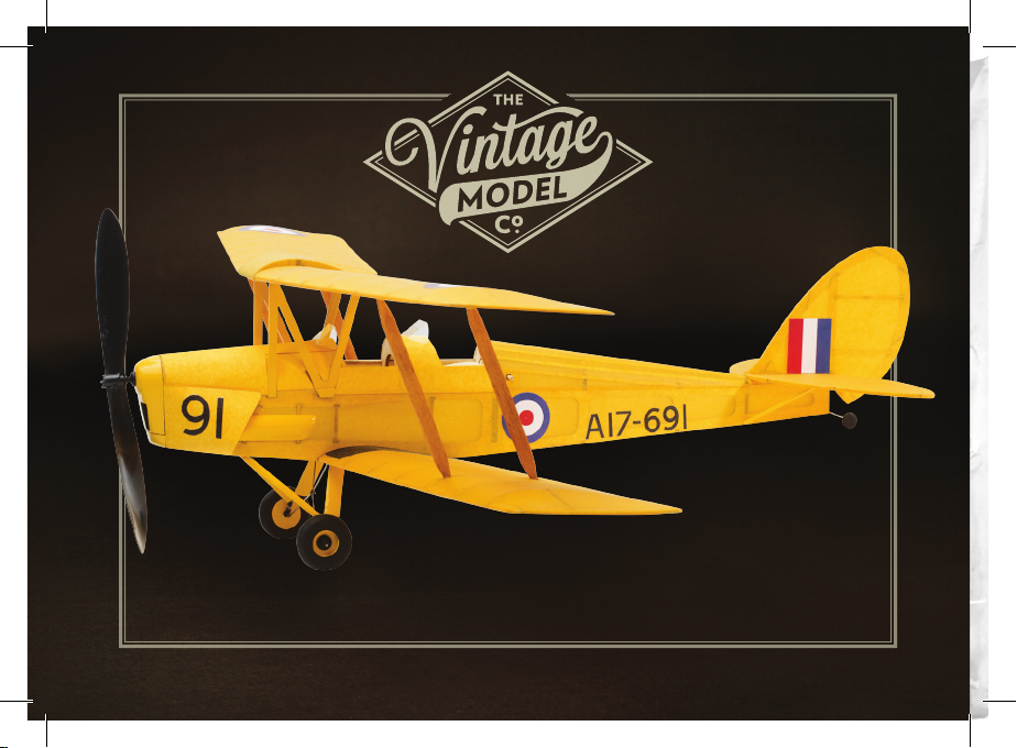
TIPS TO MAKE A GOOD JOB OF YOUR MODEL
Read and follow the instructions and the plan carefully.
• A light model will y much better than a heavy
one, so use glues and adhesives sparingly. Work
neatly and remove excess adhesive that squishes
out from joints – glue weighs far more than the
balsa wood! A piece of stiff 1.6mm square scrap
wood with the end cut at an angle makes an ideal
scraper to remove excess glue from corners or slots.
• To avoid losing the parts, remove them from the
laser cut sheets only when you need them. Use
the parts reference sheet to identify the required
part(s). Keep what remains of the balsa sheets
once the parts have been removed. This ‘scrap’
can be useful later to replace a broken part, or
make other detailed parts of your choosing.
• Balsa wood is very delicate – a light touch is
required and this is especially true when sanding.
If you have not sanded balsa before, practice on
the scrap edges of the balsa sheets. You will be
surprised by how quickly the material is removed!
• When using glue (especially cyano), don’t use it
from the tube directly. Instead, drop some onto
a non-porous disposable surface such as clean
foil from a yoghurt pot lid. Alternatively, save
pistachio nut shells – one held upright and rm
on a piece of Blu-Tack or plasticine makes an
ideal disposable glue container. You can then
pick up precise amounts of glue on the end of
a pin or piece of wire to apply to the parts. This
saves overuse of the glue and the potential
embarrassment of sticking yourself or other items
to your model!
• All of the contact surfaces of the parts to be
joined should be covered in glue.
• To remove the balsa parts, cut through the tabs
that join them to the sheets with a sharp craft
knife or scalpel – do not try to snap them from the
sheets as they may split. Remove the remains of
the tab with a light sanding.
• Some parts have a laser engraved letter ‘T’
on them – this means that the part should be
orientated with the letter T to the top when it is
correctly assembled.
• If you decide to paint your model, then use paint
sparingly. It is very easy to add weight with paint
and your model will not y well if it is too heavy.
VMC Instruction Booklet - Tiger Moth JAN19.indd 8 19/01/2019 12:26

9
Tiger Moth
• The balsa sheets are graded. Sheet 1 and 2 are hard
and strong but heavy – they are used for parts where
strength is in preference to weight. Sheets 3 and 4
are weaker and softer but light and are used for parts
where lightness is key, obviously at the expense of
strength. There are long lengths of cut balsa (known
as strip) on both the ‘light’ and ‘heavy’ sheets, so use
strip wisely and as suggested by the instructions to
make things as strong and light as possible.
• Never push pins through the balsa parts or strip,
(unless specically told to do so) – it will weaken
them or cause the wood to split. Use pins each
side of the parts either angling them or using the
head to hold the parts down.
• Never force a part to t – check and adjust it until
it ts snugly but without force.
• Pin parts together tightly but be careful not to crush
or damage the wood – a tight joint is a strong one.
• Trial t the parts before gluing and carefully adjust
them if required. They are cut accurately, but
small errors can occur between the parts and the
printed plan. Wood is a natural material and its
thickness may vary – it will contract and/or expand
after the parts are laser cut.
• You can work on several parts at one time.
For instance, you can make up the wheels and
undercarriage at the same time as something else
is setting. Just make sure you read through the
instructions rst and follow a logical sequence.
• If you have never bent wire parts before, then grab
a few paper clips and practice on those with your
pliers, before committing to bend the (expensive)
piano wire in the kit. Use a ne Sharpie marker to
mark the position of each bend as you go along.
• The internet contains a huge amount of
information to help you build your model.
Searching for terms such as ‘free ight scale’ and
‘stick and tissue’ will yield example builds and a lot
of useful information to help you with your build.
• Above all… take your time!
VMC Instruction Booklet - Tiger Moth JAN19.indd 9 19/01/2019 12:26

10
vintagemodelcompany.com
MAIN PARTS AND FRAMES
BUILDING SCHEDULE
THE CENTRE SECTION ‘FUEL TANK’
1) Identify and remove all of the parts on the laser
cut sheets: CS1, CS2, CS3, TR1 and TR2
(2 off each), and 4 off corner gussets.
2) Pin down CS1 and CS2 over the outlines on the
plan. Check the t at each end using the ribs
TR2 as a guide.
3) Glue in position the TR1 ribs both sides, making
sure that they are securely glued to all of the
other parts.
4) Glue CS3 in position, ensuring that the slots align
with the TR1 ribs and it ts snugly. Remove any
excess glue from all joints and slots.
5) Glue the corner gussets where shown and allow
things to set for a while.
6) Now glue a TR2 rib to the outside of the TR1
rib each side, lining it up with the extensions of
the parts CS3. Ensure that any excess glue is
removed, especially in the ‘pockets’ where the
tops of the cabane struts will t later on.
7) Once the glue has set, remove the centre section
from the plan.
8) Round off the leading edge and taper the trailing
edge as shown on the plan. Carefully give the
entire structure a light sanding to smooth the
joints, remove lumps and bumps and the burnt
edges of the laser parts.
VMC Instruction Booklet - Tiger Moth JAN19.indd 10 19/01/2019 12:26

11
Tiger Moth
THE MAIN WING PANELS
There are obviously two sets of wings to build.
On the Tiger Moth, the upper and lower wings are
very similar apart from their shape/angles at the root
and the differences in the ribs to allow attachment
of the cabane and inter-planar struts, etc., so
follow the instructions and the plan very carefully
to avoid mistakes.
UPPER WINGS
1) Identify and remove one set of parts in the
following quantities from the laser cut sheets:
1 off each W1U, W2U, W3-W7,W8U, W9U,
R1 (5 off), R2 and R3. You will also require the
dihedral gauge DGU. Note: to avoid error and
mix ups, remove the two parts DGU at the same
time and mark them up.
2) On the left hand top wing outline, pin down the
leading and trailing edges W1U and W2U along
with the tip piece W3 and curved part W7 and
a stiff 1.6mm square strip that forms the lower
wing spar. Note that the spar nishes inside the
notch of the wing tip piece W3.
3) Trial t the inner and outer ribs and make
any minor adjustments to the positions of the
previously pinned down parts as necessary.
Once you are satised, glue W3 and W7 in
place along with the gusset pieces W5 and W6
ensuring neat and strong butt joints.
4) Fit the inner rib R2 tilting it using the dihedral
gauge DGU as shown on the plan.
5) Fit and glue all of the remaining ribs making sure
that they are upright and properly located in the
lower spar, leading and trailing edges and that
rib R3 is tted in the correct position.
6) Glue W4 in position on top of the bottom spar
and up to the outer rib.
7) Fit a stiff 1.6mm square strip as the upper spar,
noting that it runs from the notch of the outer
rib and extends out from the inner rib as shown
on the plan.
VMC Instruction Booklet - Tiger Moth JAN19.indd 11 19/01/2019 12:26

12
vintagemodelcompany.com
8) Glue the corner gusset pieces W8U and W9U in
position along with the light 1.6mm square strip
pieces at the base of the ribs R3 as shown. These
strips bridge the slots where the cabane and
inter-planar struts will t later. Make sure that no
glue goes into the slots, otherwise the mating
parts may not t together properly later on.
9) Repeat for the right hand wing panel. Leave
both panels to set before removing them from
the building board.
10) For both wings, round off the leading edges and
taper the trailing edges as shown on the plan.
Carefully give the entire structure a light sanding
to smooth the joints, remove lumps and bumps
and the burnt edges of the laser parts.
11) The upper wings are nally joined to the centre
section after covering, but trial t the parts and
make any minor adjustments as required.
LOWER WINGS
1) Identify and remove one set of parts in the
following quantities from the laser cut sheets:
1 off each W1L, W2L, W3-W6,W8L, W9L, R1
(5 off), R4 R4A (2 off) R4b (2 off) and R5. You
will also require the dihedral gauge DGL. Note:
to avoid error and mix ups, remove the two parts
DGL at the same time and mark them up.
2) On the left hand top wing outline, pin down the
leading and trailing edges W1L and W2L, along
with the tip piece W3 and a stiff 1.6mm square
strip that forms the lower wing spar. Note that
the spar nishes inside the notch of the wing tip
piece W3.
3) Trial t the inner and outer ribs and make
any minor adjustments to the positions of the
previously pinned down parts as necessary.
Once you are satised, glue W3 in place along
with the gusset pieces W5 and W6 ensuring neat
and strong butt joints.
4) Fit the inner R5 rib, tilting it using the dihedral
gauge DGL as shown on the plan.
VMC Instruction Booklet - Tiger Moth JAN19.indd 12 19/01/2019 12:26

13
Tiger Moth
5) Fit and glue all of the remaining ribs making sure
that they are upright and properly located in the
lower spar, leading and trailing edges and rib R4
is tted in the correct position.
6) Glue W4 in position on top of the bottom spar
and up to the outer rib.
7) Fit a stiff 1.6mm square strip as the upper spar,
noting that it runs from the notch of the outer
rib and extends out from the inner rib as shown
on the plan.
8) Glue the corner gusset pieces W8L and W9L
in position along with the parts R4A and R4B
to both sides of the R4 rib as shown. These
parts bridge the slots where inter-planar struts
will t later so make sure that no glue goes into
the slots otherwise the mating parts may not t
together properly later on.
9) Repeat for the right hand wing panel. Leave
both panels to set before removing them from
the building board.
10) For both wings, round off the leading edges and
taper the trailing edges as shown on the plan.
Carefully give the entire structure a light sanding
to smooth the joints, remove lumps and bumps
and the burnt edges of the laser parts.
DECALAGE JIGS.
Bi-planes are somewhat more complicated to
construct than a monoplane. This is due to the fact
that not do the wings and tail plane need to align
properly, but each set of wings has to align too. This
is made even more complicated on the Tiger Moth
as the wings are unevenly swept and have different
dihedral angles.
VMC have designed ‘decalage jigs’ to help ensure
that the wings are correctly set to each other.
Although these jigs will not form part of the model
and take to the air, their careful construction will
mean that the important parts that do y (the
wings!) will align properly. It is very important that
the jigs are built accurately, so take your time.
1) Identify and remove all of the parts on the laser
cut sheets: WD1 (4 off).
VMC Instruction Booklet - Tiger Moth JAN19.indd 13 19/01/2019 12:26

14
vintagemodelcompany.com
2) Referring to the wing decalage jig outlines on
the plan, cut four pieces of 4.8mm wide strip to
the lengths shown and set them aside (all four
pieces are the same length).
3) Pin down 2 off parts WD1 over the plan for
the ‘inner’ dihedral jig where shown. It is very
important that the parts are pinned down
accurately to the outlines on the plan, especially
in the area of the ‘notch’ on the upper edge.
4) Glue the strips on top of the parts WD1 as
shown – their exact placement is not critical, but
they should not in any way overlap the ‘notch’.
5) Once the glue is set, remove the jig from the
plan/board and mark it ‘inner’ to reduce the
chance of a mix up later in the build.
6) Repeat the steps for the ‘outer’ decalage jig
with the second pair of WD1 parts and 4.8mm
wide strip.
Set both jigs aside until they are required later on in
the build.
CABANE STRUTS
1) Identify and remove parts in the following
quantities from the laser cut sheets: 2 off each
C1-C5.
2) Make up the two cabane strut assemblies as
shown on the plan. Be careful to follow the
instructions carefully to make up the correct left
and right hand parts. Work accurately as they
are critical to the alignment of the wings once
the model is assembled.
VMC Instruction Booklet - Tiger Moth JAN19.indd 14 19/01/2019 12:26

15
Tiger Moth
THE TAIL PLANE (STABILIZER)
NB. for both the tail plane and n rudder, when light
1.6mm strip is required, use it carefully as at least
6 full lengths are required for the completion of
the fuselage.
1) Identify and remove all of the parts on the laser
cut sheets: 1 off T1, 2 off T2- T5, 1 off T6 and 2
off corner gussets.
2) From the stiff 1.6mm square strip, cut a length
for the centre rib using the plan to get the right
length and set it aside.
3) From the light 1.6mm square strip, cut all of the
other ribs using the plan to get the right length.
Set these aside.
4) Pin down the tail plane central spar T1.
5) Lay out the parts starting at T6 and work round
in each direction, making any small adjustments.
When you are satised, glue all the parts in
position making sure that you have nice neat
butt joints. Allow this outline to set.
6) Once the outline is set, glue all of the ribs in
place adjusting the length if necessary. Then add
the two corner gussets.
7) Leave to set, then remove from the board and
give both sides as well as the outside edges
a light sand. Be careful so as not make the
structure too thin or cause unevenness in the
surface by over sanding.
VMC Instruction Booklet - Tiger Moth JAN19.indd 15 19/01/2019 12:26

16
vintagemodelcompany.com
THE FIN AND RUDDER
1) Identify and remove all of the parts on the laser
cut sheets: FR1-FR8 and a corner gusset.
2) From the stiff 1.6mm square strip, cut a length
for the base rib (which eventually sits on top of
the tail plane) and set it aside.
3) From the light 1.6mm square strip, cut all of the
ribs using the plan to get the right length. Set
these aside.
4) Pin down the n and rudder central spar FR1.
5) Lay out the parts starting at FR2 and work round
in each direction, making any small adjustments
as required.
When you are satised, glue all the parts in position
making sure that you have nice neat butt joints.
Allow this outline to set.
6) Once the outline is set, glue all of the remaining
ribs in place adjusting the length if necessary,
then add FR7 and the corner gusset.
7) Leave to set then remove from the board and
give both sides as well as the outside edges a
light sand. Be careful not to make the structure
too thin or cause unevenness in the surface by
over sanding.
VMC Instruction Booklet - Tiger Moth JAN19.indd 16 19/01/2019 12:26

17
Tiger Moth
THE FUSELAGE
At this point the major side pieces of the fuselage
should be very carefully handled as before the
various stiffeners and other structural parts are
added, they are reasonably delicate and should
be handled with care.
Preparing all of the parts:
1) Identify and remove all of the parts on the laser
cut sheets: 2 off K1, 2 off K2 F1, F2, F3A, F4,
F5 F6 and F7.
2) Pin the two fuselage sides K1 down onto the
board so that they are ‘mirrored’ (see sketch on
the plan). Although it is not strictly necessary to
pin them down, it does help to ensure that you
end up with two mirrored parts i.e. a left hand
and a right hand.
3) Glue parts K2 in position on each fuselage side,
noting that it ends before the notch at the F4
position and should be around 3mm below the
top edge of the ‘tab’ – this makes a recess where
the cabane struts will eventually t.
4) Referring to the plan, on each fuselage side (K1)
glue a piece of stiff 1.6mm square strip in the
slots beneath the K2 position to ‘bridge’ the slot.
Now add light 1.6mm square strips at the F8 and
F9 positions where shown.
5) Referring to the plan, glue 1.6mm square and
4.8mm strip ‘strengtheners’ on F3A, F4, F5,
F6 and F7 where shown, ensuring that they do
not overhang the edges of the parts. Note the
orientation of the strips on F7.
6) Laminate parts F1 and F2 together, making
sure that the proles and the square holes align
correctly. Pin the parts down to keep them at
and ensure that any glue that squishes out from
the parts is removed from the edges, notches,
and slots, otherwise the parts may not t
together well later.
7) Remove all of the parts from the board once
set and put them aside for the next stage of
construction.
VMC Instruction Booklet - Tiger Moth JAN19.indd 17 19/01/2019 12:26

18
vintagemodelcompany.com
FUSELAGE ASSEMBLY
1) As well as all of the parts as prepared in the
previous steps, identify and remove all of the
parts on the laser cut sheets: K3, K4 (2 off), K5
F3, F8, F8A, F9, F9A and F10.
2) Pin down one K1 so that the strip on it faces
upwards then t and glue F3A, F4, F6 and F7 in
position ensuring the strengtheners are facing in
the direction as indicated on the plan. Make sure
that all of the formers are at right angles to the
fuselage side using a square. Now leave to set.
3) Glue the second fuselage side to the opposite
end of the formers, again making sure that all
is located square and true. Leave to set before
removing from the board, then t part F5
making sure it is square and true in all directions.
4) On the outside of each part K1, score about half
the depth (not cut through) the part along a line
immediately in front of F3A – noted ‘score line’
on the plan. Each side should then be ‘cracked’
inwards forming a sharp kink in the side rather
than a gentle bow.
5) Bring the nose together tting the F1 and F2
assembly along with part K3. Take care to make
sure that the tabs on the fuselage locate neatly
into the slots in F2 – it should appear to be at
a slight downward angle. Allow the glue to set
before proceeding.
6) Fit part F3 making sure that it is square and true
in all directions.
7) On the outside of each part K1, score about half
the depth (not cut through) the part along a
line immediately behind F7 – noted ‘score line’
on the plan. Each side should then be ‘cracked’
inwards forming a sharp kink in the side rather
than a gentle bow.
8) Fit F10, then allow to set fully before ‘cracking’ the
fuselage sides along the score line immediately
behind it. Pinch rear of fuselage together and
glue it, along with part K5 on top, ensuring that
the ends meet uniformly and the fuselage remains
straight and true – use the gauge lines on the plan
to help. Hold the ends together with a clothes
peg or similar until the glue is set.
VMC Instruction Booklet - Tiger Moth JAN19.indd 18 19/01/2019 12:26

19
Tiger Moth
9) Fit formers and cross pieces F8, F8A, F9 and
F9A top and bottom working backward ensuring
that the fuselage remains square and true in
all directions.
10) Using stiff 1.6mm square strip t and glue the
‘backbone’ stringer in position, then t the two
lower stringers each side – noting that they start
midway into part F5, are cracked at F7, and then
taper into the fuselage before F9.
11) Referring to the diagram illustrating their
nishing positions, t and glue the remaining
rear stringers that run from F7 – making them
from light 1.6mm square strip.
12) Fit the three short stringers that run from F5 to F6.
13) Fit three stiff 1.6mm square strip stringers
between F2 and F4, then the two lower stringers
that run from F3 to the fuselage side at F2,
bevelling the ends to suit.
14) Carefully cut two pieces of 4.8mm strip that will
go from side to side and form the slots for the
undercarriage. At the front position, glue one
piece in place leaving a gap of around 1mm (the
thickness of a credit card) between it and the
strengthener at F3A – this gap will eventually
accommodate the wire. At the rear position, glue
in place leaving a gap of around 2mm between
it and the face of F4 – this gap will eventually
accommodate the undercarriage ‘strap’.
15) Starting with the left hand side, trial t K4
bevelling the edges to meet the stringer at the
top as required. Ensure a snug and ush t to
the outer prole, then glue in position. Repeat
with part K4 on the right hand side.
VMC Instruction Booklet - Tiger Moth JAN19.indd 19 19/01/2019 12:26

20
vintagemodelcompany.com
THE WHEELS, UNDERCARRIAGE
AND TAIL SKID/WHEEL
1) Using wire cutters and pliers, make up the wire
pieces that constitute the main undercarriage
and tail wheel/skid. Note the aircraft on which
this kit is based has a wheel, but many have skids
– choose whichever suits.
2) Make up the main undercarriage following the
steps on the plan. The cotton thread binding
should be strengthened using cyano, but ensure
that the wire parts can pivot on the ‘strap’ to
allow for angular adjustment when it is tted to
the fuselage later. Note that where wire parts are
joined, the cotton thread can be exchanged for
wrapping with ne wire and then soldering.
3) Identify and remove parts in the following
quantities from the laser cut sheets: 4 off WH1
and 4 off WH2. Note: retain part TW that sits
inside one of the WH1 parts.
4) Sand the internal diameter of the WH1 parts to
remove the ‘tags’ and burnt edges using a piece
of sandpaper wrapped round a pencil or similar.
5) Laminate the parts cross-grained as shown on
the plan to make 2 wheels, making sure all of the
parts stay concentric. Once they are set, round
the edges off as shown on the plan. If you want
to paint the wheels they should be coated with
full strength dope and sanded to a smooth
nish beforehand.
6) Fit a plastic nose bush to each wheel using cyano
adhesive. DON’T ALLOW THE ADHESIVE
TO GO INSIDE THE BUSH.
7) If having a tail wheel rather than a skid, glue part
TW1 to the centre of the tail wheel wire with
cyano. Allow it to dry then sand the wood ush
to the wire.
8) Set all of the wheels, undercarriage and tail skid
parts aside until they are assembled to the
model later.
VMC Instruction Booklet - Tiger Moth JAN19.indd 20 19/01/2019 12:26
This manual suits for next models
1
Table of contents
Other Vintage Model Co Toy manuals

Vintage Model Co
Vintage Model Co OSPREY User manual

Vintage Model Co
Vintage Model Co SE5A User manual

Vintage Model Co
Vintage Model Co JODEL D-18 User manual

Vintage Model Co
Vintage Model Co MESSERSCHMITT BF109 User manual

Vintage Model Co
Vintage Model Co Balsa Basics Spitfire Instruction Manual

Vintage Model Co
Vintage Model Co CESSNA 140 User manual

Vintage Model Co
Vintage Model Co SOPWITH F1 CAMEL User manual