Visicomm 3KSS60400 User manual

USER’S MANUAL
3KSS60400/50400
2nd Edition
Frequency Converter
Visicomm Industries LLC
4525 Sheridan Rd.
Racine WI 53403

1
1. INTRODUCTION
The conversion of electrical power is an essential requirement for export testing or
operation of equipment brought to the U.S. from abroad. The KSS series Frequency
Converter is designed to meet these needs as it supplies reliable, pure and stable
power at an affordable price.
This Converter is designed with the following unique features
lDouble Conversion IGBT module, Single control board design, eliminates
adjustment, and minimizes maintenance.
lLCD display for unit status, user friendly design
lSpecial overload capacity design, 150% overload for 30 sec.
lBuilt-in isolation transformer to ensure total isolation between the input and
output.
lSpecial airflow control to avoid dust accumulation. Suitable for any rough
operating environments.
lCompact size, light weight.

2
2.1 FRONT PANEL
1. LINE LED: This indicates the incoming AC line is
normal.
3. INVERTER LED: This means the converter power is
supplied from inverter.
6. FAULT LED: This indicates the converter is in fault
condition.
7. LCD DISPLAY
(1) INPUT VOLTAGE (3) INPUT FREQUENCY
(2) OUTPUT VOLTAGE (4) OUTPUT FREQUENCY
(5) OUTPUT POWER
(6) NO OUTPUT
8. LCD Switch: Display items can be changed using the
LCD switch.
9. PUSH ON-OFF SWITCH: This switch turns the
converter on or off.
10. VENTILATION LOUVERS: Please keep the
ventilation louvers clean.
3KSS60400/50400
FREQUENCY CONVERTER
(FRONT)

3
CAUTION:
SINGLE PHASE 120V OUTPUT
CONNECT N TO THE SYSTEM
"NEUTRAL". L1 IS THE 120V
OUTPUT
2.2 REAR PANEL
11. LCD Display
selector switch.
12. Frequency selector
switch
13. Main Input breaker
(SWA). Controls the
ACCommercialinput
Power, in addition
This breaker trips
If the output power
Is subject to a
Dead short.
14. Input terminal: The
input power leads
will be connected to
the terminal block
either 120VAC range
or 220VAC range
(See spec. sheet)
15. output terminal:
120V L-N
16. output Voltage
adjustment
potentiometer
17. Ground terminal
3KSS60400/50400
FREQUENCY CONVERTER
(BACK)

4
Input Power Connections and Grounding
System Ground Connection:
The Earth Ground should be provided by the utility. This is normally the “GREEN” wire
provided by the utility which at some point is routed to a secure earth ground such as a water
pipe. This wire should be connected to the screw post marked GND on the Converter (See
photo for location).
Note that there are no internal electrical connections to this wire with the exception of a
small high frequency bypass capacitor for RF suppression. Therefore, the function of the Earth
Ground is simply to maintain the case of the Converter at ground potential. Visicomm Industries
(LLC) does not recommend any other connection to the Earth Ground wire which may introduce
significant amounts of current and thereby defeat the intended purpose of this wire which is the
safety of the operating personnel. In particular, do not connect this wire to the system neutral
wire at any point.
OutputConnection:
The Power OUTPUT Connections are provided by three barrier terminal posts labeled N,
L1, and L2. These three terminals constitute the three terminals of an internal auto-trans former
were L1 is the “center tap”. This is fed by the output winding of a switching transformer. Since
the only other internal connections are a resonating capacitor, the cooling fans, and sensing
circuits( to maintain an output sine wave ), these output terminals are electrically isolated from
any other circuits including the system neutral.
The Converter is shipped with these OUTPUT connections electrically isolated. If a digital
voltmeter is connected between any one of these OUTPUT terminals and the Earth Ground, a
significant voltage reading will be obtained. This voltage is due to a small leakage current and is
not considered a problem since only 1 or 2 ma is involved.
OutputIsolation:
Many applications require an isolated output,primarily for safety reasons, when supplying
power to a device under test especially if there will be other monitoring equipment connected to
the device. Other applications can take advantage of the low leakage current of the Converter
(about 1 or 2 ma). This can be useful in systems where the individual leakage currents of the
components might exceed the allowed leakage current of a ground fault interrupter.
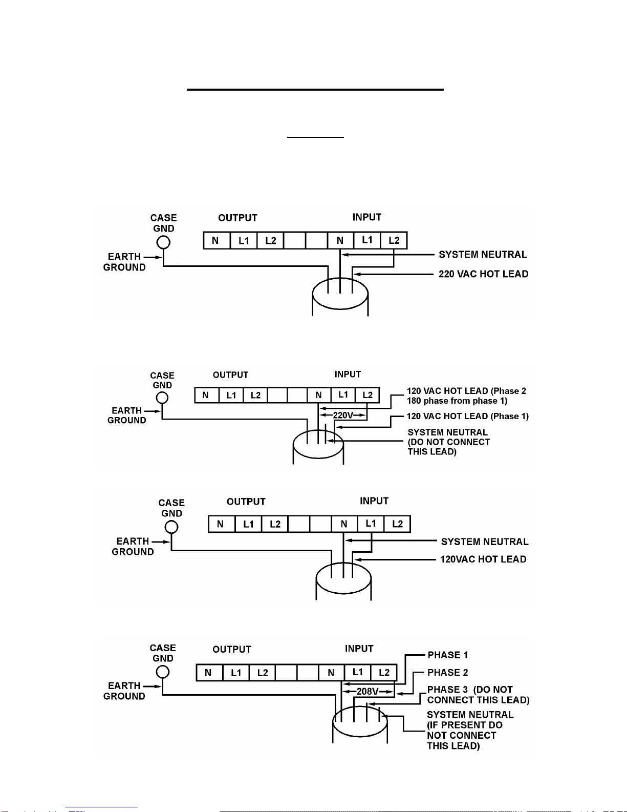
Other applications require that the output have a connection to the utility NEUTRAL.
Normally this would be OUTPUT terminal N (The exception would be a two phase output where
L1 would be the connection to the system NEUTRAL). The Converter is supplied with a short
jumper wire. If the system NEUTRAL is used to power the INPUT terminals and it is required that
the OUTPUT be connected to NEUTRAL this jumper can be employed to make this connection.
If the INPUT is supplied by two phase AC or by two phases of a three phase system (in
other words, if you have only two incoming power wires), this NEUTRAL would not be present
and an external wire from the desired OUTPUT terminal to the system NEUTRAL would be
required. See INPUT CONNECTION DIAGRAM on next page.
N
L1
L2
Basic diagram of output stage

5
INPUT POWER CONNECTIONS
The frequency of the input power can be 50 or 60 Hz, and is not related to the output frequency
CAUTION:
The Input is Electrically Isolated from the output.
It is necessary to connect the input using one of the following four methods.
A. SINGLE PHASE 220V INPUT
This connection is usually used in 50Hz countries where a neutral is normally available.
B. SPLIT PHASE 220V INPUT
This connection is usually used in 60Hz countries where a 220V line is not normally
available, and where the input amperage makes using 120V inconvenient.
C. SINGLE PHASE 120V INPUT
D. THREE PHASE 120/208 VAC USING LINE TO LINE INPUT
To be used if the 120V line to neutral connection is limited by the amperage available.

6
OUTPUT POWER CONNECTIONS
The frequency of the output power is 400 Hz, and is not related to the input frequency
CAUTION:
The output is "floating" and is electrically isolated from the input.
It is necessary to connect the output using one of the following three methods.
Note that these output voltages are widely adjustable using the voltage adjust rheostat.
A. SINGLE PHASE 120V OUTPUT

7
4. SPECIFICATION
Model 3KSS60400/50400
Capacity 3KVA /2.1kW Input Current Requirement @ 220V , 16A –120V, 30A
Voltage 120 or 220VAC
Voltage Range 120V –15%/+20% or 220V –15%/+20%
Frequency 50 Hz or 60 Hz ± 5%
Input
Phase Single
Voltage 120VAC ± 20%
Voltage Regulation ± 1 %
Frequency 400Hz (50 Hz or 60 Hz available)
Frequency Regulation ± 0.0004% (xtal oscillator)
Harmonic Distortion < 3% at 100% Linear Load
Output Waveform Pure Sinewave
Output Current @ .7pf 120V-25A, 220V-13.6A
Output
Non-Linear Peak Current 120V-37.5A, 220V-20.4A for 30 sec.
Power Factor 0.7
Efficiency AC to AC > 85%
OverloadCapacity 110%continuous, 110-150% load 30 seconds, ov
er 150% causes unit
to shut down. Auto restart upon removal of overload
Short Circuit Unit will cut out and must be manually restarted
EMI Filter 10-100KHz at 40dB, 100KHz-100MHz at 70dB
Protection
Over Temperature Inverter auto cut-off when heat sink temp. over 80ºC.
Overload Sounds continuously
Audible Alarm Converter Fault Sounds continuously
LCD Converter status, INPUT & OUTPUT voltage-frequency, loading %
Indicators LED Line: Green LED
Fault: Red LED Inverter: Green LED
Overload: Yellow LED
Operation Temp. -10ºC to 50ºC; 14ºFto 122ºF
Relative Humidity 20-90% non-condensingEnvironment Audible Noise <45dB
Net Weight 144lbs / 64.8kg
Depth 21.75in / 55.25cm
Width 7in / 17.78cm
Physical
Dimensions
Height 19in / 48.26cm
This manual suits for next models
1
Table of contents
Other Visicomm Inverter manuals