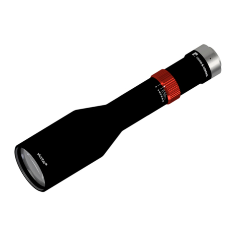
Vision & Control TOB42/11.0-185-F16-WN User manual

creating machine vision VISION & CONTROL
Instructions for Use
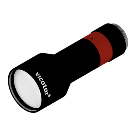
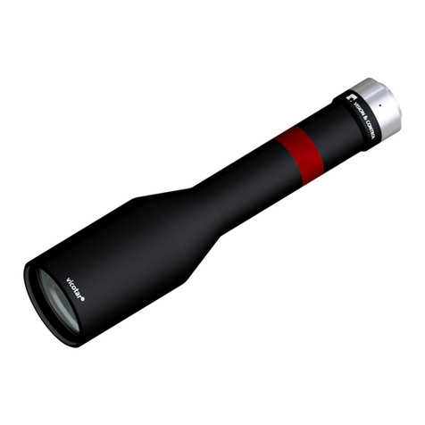
TOB42/11.0-185-F16-WN
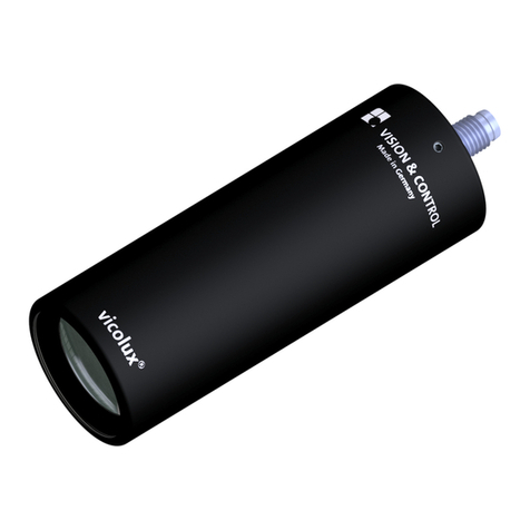
Telecentric measurement lens
Instructions for Use
TOB42/11.0-185-F16-WN
Telecentric measurement lens
999.995.970.10-en-3.0
© Vision & Control GmbH 2022

Impress
Publisher / Manufacturer Vision & Control GmbH
Mittelbergstraße 16
98527 Suhl, Germany
Telephone: +49 (0) 3681 7974-0
www.vision-control.com
Name of the document 999.995.970.10-en-3.0
Date of first issue 2019-09-12
Date modified 2022-09-06
Copyright © Vision & Control GmbH 2022
Copyright
It is forbidden to pass this document on to third parties, reproduce and
communicate its contents in as far as this has not been expressly authorized.
Offenders will be liable for damages.
All rights are reserved with respect to patent, utility sample and design patent
registrations, as well as for rights of use within the scope of copyright.
vicotar®, vicolux®, pictor®, vicosys® and vcwin® are registered trademarks of
Vision & Control GmbH.
The products and brand names of other manufacturers or suppliers are
mentioned for information only.
2 -- © Vision & Control GmbH 2022

Validity
These instructions for use are valid for the following device:
Device Order no.
TOB42/11.0-185-F16-WN 2-05-603
Product Identification
Designation Description
TOB Bi-telecentric measurement lens
42 Maximum object field diameter in mm
11.0 Maximum image sensor diagonal in mm
185 Working distance in mm
F16 Fixed aperture: F16
WN Spectral range
W - white light - 465 nm - 635 nm
N - near infrared - 780 nm - 950 nm
© Vision & Control GmbH 2022 -- 3

TOB42/11.0-185-F16-WN
Table of Contents
TABLE OF CONTENTS
1 Information about the Instructions of Use..................................................6
1.1 Intended Use................................................................................................ 6
1.2 Improper Use................................................................................................7
1.3 Qualified Personnel...................................................................................... 7
1.4 Warranty and Liability...................................................................................8
2 Safety.............................................................................................................. 9
2.1 Presentation of Safety Instructions.............................................................. 9
2.2 Safe Handling of the Device...................................................................... 10
3 Scope of Delivery and Accessories.......................................................... 11
3.1 Scope of Delivery....................................................................................... 11
3.2 Accessories.................................................................................................11
4 Device Description...................................................................................... 16
4.1 Device Views.............................................................................................. 16
4.2 Notices on the device.................................................................................16
5 Technical Data............................................................................................. 17
5.1 General Parameters................................................................................... 17
5.2 Optical Parameters.....................................................................................18
5.2.1 Resolution...........................................................................................19
5.2.2 Depth of field...................................................................................... 20
5.2.3 Absolute Distortion............................................................................. 21
5.2.4 Telecentricity....................................................................................... 21
5.3 Optical characteristics (design data).......................................................... 22
5.3.1 MTF depending on the Spatial Frequency.........................................23
5.3.2 MTF depending on the Image Field................................................... 26
5.3.3 Lateral chromatic aberration...............................................................29
5.3.4 Longitudinal Chromatic Aberration..................................................... 29
5.3.5 Distortion.............................................................................................29
5.3.6 Vignetting............................................................................................30
5.4 Conditions for Operation, Storage and Transport...................................... 31
5.5 Technical Drawings.....................................................................................32
6 Commissioning............................................................................................ 33
6.1 Unpacking................................................................................................... 33
6.2 Mounting..................................................................................................... 33
6.2.1 Mounting at the clamping area...........................................................34
6.2.2 Mounting of filters...............................................................................34
4 999.995.970.10-en-3.0 © Vision & Control GmbH 2022
TOB42/11.0-185-F16-WN
Table of Contents
6.2.3 Mounting at the camera..................................................................... 34
6.3 Configuration...............................................................................................35
6.3.1 Setting the working distance.............................................................. 35
7 Operation...................................................................................................... 36
8 Maintenance and Service........................................................................... 37
8.1 Maintenance............................................................................................... 37
8.2 Service........................................................................................................ 39
9 Disposal........................................................................................................ 40
Table of Figures
1: Device view.................................................................................................16
2: Type plate................................................................................................... 16
3: Illustrative sketch of optical characteristics................................................ 22
4: MTF - spatial frequency dependent (470 nm, F16, WD 183.4 mm)........... 23
5: MTF - spatial frequency dependent (525 nm, F16, WD 182.4 mm)........... 23
6: MTF - spatial frequency dependent (635 nm, F16, WD 182.2 mm)........... 24
7: MTF - spatial frequency dependent (850 nm, F16, WD 183.6 mm)........... 24
8: MTF - spatial frequency dependent (white, F16, WD 182.6 mm)...............25
9: MTF - image field dependent (470 nm, F16, WD 183.4 mm).....................26
10: MTF - image field dependent (525 nm, F16, WD 182.4 mm).....................26
11: MTF - image field dependent (635 nm, F16, WD 182.2 mm).....................27
12: MTF - image field dependent (850 nm, F16, WD 183.6 mm).....................27
13: MTF - image field dependent (white, F16, WD 182.6 mm)........................ 28
14: Lateral chromatic aberration - wavelength dependent............................... 29
15: Longitudinal chromatic aberration - wavelength dependent....................... 29
16: Distortion - wavelength dependent.............................................................30
17: Vignetting.................................................................................................... 30
18: Assembly regions....................................................................................... 33
19: Illustrative sketch - working distance..........................................................35
© Vision & Control GmbH 2022 999.995.970.10-en-3.0 5

TOB42/11.0-185-F16-WN
Information about the Instructions of Use
1 INFORMATION ABOUT THE INSTRUCTIONS OF
USE
This document contains technical information, important instructions for correct
installation, commissioning and use, as well as product information which were
up-to-date at the time of going to press.
Using this document makes it easier for you to familiarise yourself with the
device and avoid malfunctions caused by improper operation.
The instructions of use and the local regulations and rules must be followed.
To ensure a save and proper application, please read the instructions of use
carefully and keep them for future reference.
1.1 Intended Use
The device is intended exclusively for use as an imaging element for industrial
image processing.
The device is intended for use in a confined environment.
The device may only be used if it is in technically faultless condition and only
for its intended purpose, and only in accordance with the specifications in this
instructions of use by authorised operative personnel, who are aware of the
safety rules and hazards.
If the device is planned to be used for any other purpose or in a different
environment, the express authorisation of the manufacturer must be obtained
in advance. Any modifications or adaptations required may only be made by
the manufacturer.
6 999.995.970.10-en-3.0 © Vision & Control GmbH 2022

TOB42/11.0-185-F16-WN
Information about the Instructions of Use
1.2 Improper Use
All unintended use and all device-related activities not described in these
instructions of use is to be deemed as unauthorised misuse outside the legal
limits of indemnity of the manufacturer.
Reasonably foreseeable misuse is:
•Non-compliance with the instructions for use,
•Faulty operation,
•Operating by personnel not qualified or instructed,
•Operating the device if it is not in a proper technical condition,
•Operating the device in ambient conditions differing from the corresponding
specifications in the instructions of use,
•Using spare parts which are not original parts from the manufacturer,
•Using incompatible accessory components,
•Improper maintenance and repair works,
•Unauthorised modifications to the device.
1.3 Qualified Personnel
The device may only be assembled, commissioned, operated, maintained,
installed, set up, cleaned, repaired and transported by qualified skilled
personnel.
A qualified person is deemed to be someone who has been trained and
instructed for his/her activities with the device, and who has proven his/her
capability to the purchaser. The operating personnel must be authorised by the
purchaser for those activities at the device.
For the installation and operation of the device, the skilled personnel must
know and comply with the applicable guidelines and standards for handling the
device.
© Vision & Control GmbH 2022 999.995.970.10-en-3.0 7

TOB42/11.0-185-F16-WN
Information about the Instructions of Use
1.4 Warranty and Liability
The contents of this document have been checked carefully and correspond to
current legislation and best practise at the time of going to press.
However, the manufacturer shall not be liable for any damage arising from the
use of this edition of the manual, and rejects any warranty derived therefrom.
Within the bounds of the legal requirements, the manufacturer shall only
be responsible for the technical safety characteristics of the device if the
maintenance, repairs and modifications to the device are performed by himself
or by authorised skilled personnel in accordance with his instructions.
Loss of warranty
The manufacturer shall accept no liability or warranty in the event of improper
use, opening of the device or incorrect maintenance.
8 999.995.970.10-en-3.0 © Vision & Control GmbH 2022

TOB42/11.0-185-F16-WN
Safety
2 SAFETY
2.1 Presentation of Safety Instructions
Each safety instruction is introduced by a key word and colour highlighted.
The key word indicates the degree of danger. The danger and its cause are
described, and then the measures to prevent conceivable consequences of the
danger. These measures must be taken.
DANGER
Indicates an imminent danger with high risk, resulting in severe injuries or
death if not avoided.
WARNING
Indicates a hazardous situation with medium risk, possibly resulting in severe
injuries or death if not avoided.
CAUTION
Indicates a hazardous situation with low risk, resulting in minor or medium
injuries if not avoided.
NOTICE
Indicates a situation that may result in property damage.
© Vision & Control GmbH 2022 999.995.970.10-en-3.0 9

TOB42/11.0-185-F16-WN
Safety
2.2 Safe Handling of the Device
Read the following applicable safety instructions carefully and completely.
Follow the instructions for your own safety, the safety of other people, and to
avoid damage to the device and the connected technical equipment. Hazards
going beyond the general safety instructions are referred to separately at the
relevant points in this manual.
CAUTION
Eye damage
•Do not look directly through the lens.
CAUTION
Cutting injuries caused by glass breakage
The lenses of the objective are made of glass.
•Protect the objective against impact and do not drop it.
•In case of glass breakage do not touch any breakage edges.
•In case of glass breakage use cut-resistant protective gloves.
•Dispose of glass breakage using appropriate waste
containers.
10 999.995.970.10-en-3.0 © Vision & Control GmbH 2022
TOB42/11.0-185-F16-WN
Scope of Delivery and Accessories
3 SCOPE OF DELIVERY AND ACCESSORIES
3.1 Scope of Delivery
Designation Quantity
Device TOB42/11.0-185-F16-WN 1 x
Covering cap 2 x
3.2 Accessories
The following accessories are available for the lens.
Lens holder
Designation Description Order no.
Lens Holder d32 Holder for telecentric lenses and lightings with
32 mm clamping diameter, for vibration-free
attachment
2-90-122
Deflection mirrow
Designation Description Order no.
Deflection mirrow
90-56
90° deflection, attachment for telecentric
lenses and lightings with front diameter 56 mm
2-25-115
Beam Splitter Unit
Designation Description Order no.
STE60x60-VIS Beam splitter unit - merges the optical axis
of the lens or camera with the axis oft the
lighting.
1-20-050
Adapter
STE60x60 -
TZO56
Adapter for attaching the STE60x60 to
telecentric lenses and lights with 56 mm front
diameter
1-20-022
© Vision & Control GmbH 2022 999.995.970.10-en-3.0 11

TOB42/11.0-185-F16-WN
Scope of Delivery and Accessories
Adapter ringe
Designation Description Order no.
Adapter ring
d41 - M52x0.75
for R-CLR-69x41 and RK2036, for attachment
to lenses with filter thread M52x0.75
1-29-676
Adapter ring
d73 - M52x0.75
for R-CLR-100x73 and RK3652, for
attachment to lenses with filter thread
M52x0.75
1-29-772
Adapter ring
d104 - M52x0.75
for R-CLR-132x104 and RK5268, for
attachment to lenses with filter thread
M52x0.75
1-29-870
Adjustment Aids
Designation Description Order no.
Adjustment aid
10
for easy adjustment to 10 mm depth of field,
for image scale 0.5 - 0.2
5-10-112
12 999.995.970.10-en-3.0 © Vision & Control GmbH 2022
TOB42/11.0-185-F16-WN
Scope of Delivery and Accessories
CS to C-mount adapter / Extension rings
Designation Description Order no.
CS to C-mount
adapter 5.0 mm
for connecting C-mount lenses with CS-mount
cameras, length: 5 mm
2-90-414
Extension ring
0.5 mm
26 x 31 x 0.5 reduces the minimum object
distance (MOD)
2-90-415
Extension ring
1.0 mm
26 x 31 x 1.0 reduces the minimum object
distance (MOD)
2-90-416
Extension rings can reduce the ideal imaging performance specified in the
manual.
They mainly cause a change in the working distance. The magnification also
changes, but only very slightly.
The working distance is reduced by approximately the thickness of the
extension ring divided by the square of the magnification.
Parameter Value
Image scale 0.26
Working distance 185 mm
working distance with extension ring 0.5 mm 177.6 mm
working distance with extension ring 1 mm 170.2 mm
© Vision & Control GmbH 2022 999.995.970.10-en-3.0 13

TOB42/11.0-185-F16-WN
Scope of Delivery and Accessories
Filter for filter thread object-side
Designation Description Order no.
UV blocking filter
M52x0.75
Long-pass filter from 350 nm, usable as
protective glass
2-91-124
IR-Filter
M52x0.75
Long-pass filter from 830 nm (daylight
absorbing filter)
2-91-134
Colour filter red
M52x0.75
Long-pass filter with edge length λ = 630 nm 2-91-262
Colour filter blue
M52x0.75
Band-pass filter in the range from 350 nm to
600 nm
2-91-290
Colour filter green
M52x0.75
Band-pass filter in the range from 430 nm to
620 nm
2-91-303
Colour filter
yellow M52x0.75
Long-pass filter with edge length λ = 530 nm 2-91-277
Pole filter
M52x0.75
Linear polarizing filter in the range of 420 nm
to 780 nm
2-91-144
ND filter 0.6
M52x0.75
Optical density 0.6 - 25% transmission, f-stop
reduction 2
2-91-154
ND filter 1.2
M52x0.75
Optical density 1.2 - 6.3% transmission, f-stop
reduction 4
2-91-164
ND filter 3.0
M52x0.75
Optical density 3.0 - 0.1% transmission, f-stop
reduction 10
2-91-174
14 999.995.970.10-en-3.0 © Vision & Control GmbH 2022
TOB42/11.0-185-F16-WN
Scope of Delivery and Accessories
Filter for filter thread camera-side
Designation Description Order no.
UV blocking filter
M20.5x0.5
Long-pass filter from 350 nm, usable as
protective glass
2-91-121
IR-Filter
M20.5x0.5
Long-pass filter from 830 nm (daylight
absorbing filter)
2-91-131
Colour filter red
M20.5x0.5
Long-pass filter with edge length λ = 630 nm 2-91-259
ND filter 0.6
M20.5x0.5
Optical density 0.6 - 25% transmission, f-stop
reduction 2
2-91-151
ND filter 1.2
M20.5x0.5
Optical density 1.2 - 6.3% transmission, f-stop
reduction 4
2-91-161
ND filter 3.0
M20.5x0.5
Optical density 3.0 - 0.1% transmission, f-stop
reduction 10
2-91-171
© Vision & Control GmbH 2022 999.995.970.10-en-3.0 15

TOB42/11.0-185-F16-WN
Device Description
4 DEVICE DESCRIPTION
4.1 Device Views
2
5
3
4
1
Image 1: Device view
1Filter thread M52 x 0.75 4Filter thread M20.5 x 0.5
2Type plate 5Contact edge camera
3C-mount camera connection
4.2 Notices on the device
Type plate
Type: TOB42/11.0-185-FX-WN
SN.: XXXXXXXX
Type: TOB42/11.0-185-FX-WN
SN.: XXXXXXXX
2
3
1
Image 2: Type plate
1Position on the lens
2Device designation
3Serial number
16 999.995.970.10-en-3.0 © Vision & Control GmbH 2022
TOB42/11.0-185-F16-WN
Technical Data
5 TECHNICAL DATA
5.1 General Parameters
Parameter Value
Housing material Aluminium, black anodised
Optical material Glass
Housing dimensions Length: 232.0 mm (without connection thread)
Diameter: 56 mm
Clamping diameter: 32 mm and 56 mm
Camera distance 417.0 mm (working distance and lens length)
Filter thread object-side M52 x 0.75 / depth: 8.0 mm
Filter thread camera-side M20.5 x 0.5 / depth: 3.5 mm
Lens mount C-mount
Flange focal distance 17.526 mm
Aperture F16
Maximum object field diagonal 42.3 mm
Maximum image field diagonal 11 mm
Maximum sensor size 2/3"
Weight 433 g
Optimal sensor size
ADVICE
The illustrated image sensors serve as an overview. Other image sensors
with image field diagonals up to 11 mm are also possible.
11 mm
2/3"
8.8 mm
6.6 mm
9.0 mm
1/1.8"
7.2 mm
5.4 mm
8 mm
1/2"
6.4 mm
4.8 mm
© Vision & Control GmbH 2022 999.995.970.10-en-3.0 17

TOB42/11.0-185-F16-WN
Technical Data
Object fields at different sensor formats
Sensor Object field
Type Size Diagonal Size
2/3" 8.8 mm x 6.6 mm 11.0 mm 33.5 mm x 25.1 mm
1/1.8" 7.2 mm x 5.4 mm 9.0 mm 27.0 mm x 20.6 mm
1/2" 6.4 mm x 4.8 mm 8.0 mm 24.4 mm x 18.3 mm
1/3" 4.8 mm x 3.6 mm 6.0 mm 18.3 mm x 13.7 mm
1/4" 3.4 mm x 2.2 mm 4.1 mm 12.9 mm x 8.3 mm
5.2 Optical Parameters
Parameter Value
Spectral range VIS (W): 450 nm - 780 nm,
optimized at 465 nm - 635 nm
NIR (N): 780 nm - 950 nm
Effective F-number F16
Object-sided numerical
aperture
0.0079
Image-sided numerical
aperture
0.030
Image scale 0.26 ± 0.0026
Working distance W: 185.0 ± 2 mm
N: 185.8 ± 2 mm
Image length 434.36 mm
Min. pixel size 2.9 µm (at 470 nm, F16, 1/1.8"-Sensor)*
Resolution class 5 MPixel
* The lens has the best imaging performance with these parameters.
18 999.995.970.10-en-3.0 © Vision & Control GmbH 2022
TOB42/11.0-185-F16-WN
Technical Data
5.2.1 Resolution
Image field diagonal: 11.0 mm (2/3")
Aperture Spectral range MTF at
50 LP/mm
MTF at
70 LP/mm
MTF at
100 LP/mm
F16 Blue: 470 nm
Green: 525 nm
Red: 635 nm
Infrared: 860 nm
White: 470 - 635 nm
43.39 %
42.24 %
34.15 %
18.07 %
22.17 %
28.24 %
25.30 %
15.15 %
0.10 %
5.74 %
10.68 %
5.11 %
-
-
1.72 %
Image field diagonal: 9.0 mm (1/1.8")
Aperture Spectral range MTF at
50 LP/mm
MTF at
70 LP/mm
MTF at
100 LP/mm
F16 Blue: 470 nm
Green: 525 nm
Red: 635 nm
Infrared: 860 nm
White: 470 - 635 nm
49.44 %
45.03 %
35.71 %
18.37 %
38.20 %
32.64 %
26.92 %
15.58 %
0.18 %
19.20 %
11.77 %
5.47 %
-
-
3.84 %
Image field diagonal: 8.0 mm (1/2")
Aperture Spectral range MTF at
50 LP/mm
MTF at
70 LP/mm
MTF at
100 LP/mm
F16 Blue: 470 nm
Green: 525 nm
Red: 635 nm
Infrared: 860 nm
White: 470 - 635 nm
50.56 %
45.93 %
35.71 %
18.48 %
41.68 %
33.46 %
27.46 %
15.70 %
0.22 %
22.65 %
11.99 %
5.59 %
-
-
4.63 %
© Vision & Control GmbH 2022 999.995.970.10-en-3.0 19

TOB42/11.0-185-F16-WN
Technical Data
5.2.2 Depth of field
Image field diagonal: 11.0 mm (2/3") - MTF = 20 % at 20 LP/mm
Aperture Spectral range Total Range further
from the lens
Range nearer
to the lens
F 16 Blue: 470 nm
Green: 525 nm
Red: 635 nm
Infrared: 860 nm
White: 470 - 635 nm
22.6 mm
23.7 mm
24.8 mm
26.4 mm
23.8 mm
11.4 mm
11.5 mm
12.0 mm
13.0 mm
11.7 mm
11.2 mm
12.2 mm
12.8 mm
13.4 mm
12.1 mm
Image field diagonal: 9.0 mm (1/1.8") - MTF = 20 % at 20 LP/mm
Aperture Spectral range Total Range further
from the lens
Range nearer
to the lens
F 16 Blue: 470 nm
Green: 525 nm
Red: 635 nm
Infrared: 860 nm
White: 470 - 635 nm
24.9 mm
25.2 mm
25.9 mm
27.6 mm
25.4 mm
12.1 mm
12.4 mm
13.1 mm
14.2 mm
12.6 mm
12.8 mm
12.8 mm
12.8 mm
13.4 mm
12.8 mm
Image field diagonal: 8.0 mm (1/2") - MTF = 20 % at 20 LP/mm
Aperture Spectral range Total Range further
from the lens
Range nearer
to the lens
F 16 Blue: 470 nm
Green: 525 nm
Red: 635 nm
Infrared: 860 nm
White: 470 - 635 nm
25.5 mm
25.7 mm
26.4 mm
28.1 mm
25.9 mm
12.5 mm
12.9 mm
13.6 mm
14.7 mm
13.1 mm
13.0 mm
12.8 mm
12.8 mm
13.4 mm
12.8 mm
20 999.995.970.10-en-3.0 © Vision & Control GmbH 2022
This manual suits for next models
1
Table of contents
Other Vision & Control Measuring Instrument manuals

Vision & Control
Vision & Control TO66/9.0-210-V-B User manual

Vision & Control
Vision & Control TO88/6.0-290-V-B User manual

Vision & Control
Vision & Control TOB42/11.0-185-F10-WN User manual

Vision & Control
Vision & Control TOB42/11.0-145-F16-WN User manual

Vision & Control
Vision & Control TZB28-B450-P-24V User manual

Vision & Control
Vision & Control TOB42/11.0-165-F16-WN User manual

Vision & Control
Vision & Control TO30/9.1-85-F10-B-RF User manual

Vision & Control
Vision & Control TO44/6.2-150-V-B User manual

Vision & Control
Vision & Control TOB42/11.0-165-F10-WN User manual

Vision & Control
Vision & Control TOB42/11.0-145-V-WN User manual