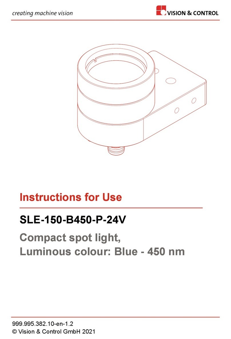
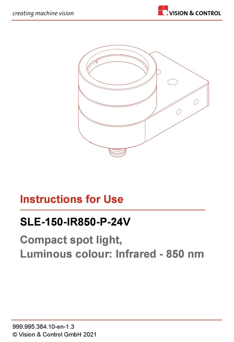
Vision & Control SLE-150-G530-P-SL User manual

creating machine vision VISION & CONTROL
Instructions for Use
SLE-150-G530-P-SL
Compact spot light,
Luminous colour: Green - 530 nm
Instructions for Use
SLE-150-G530-P-SL
Compact spot light,
Luminous colour: Green - 530 nm
999.995.381.10-en-1.3
© Vision & Control GmbH 2021

Impress
Publisher / Manufacturer Vision & Control GmbH
Mittelbergstraße 16
98527 Suhl, Germany
Telephone: +49 (0) 3681 7974-0
Telefax: +49 (0) 3681 7974-33
www.vision-control.com
Name of the document 999.995.381.10-en-1.3
Date of first issue 2020-11-18
Date modified 2021-01-18
Copyright © Vision & Control GmbH 2021
Copyright
It is forbidden to pass this document on to third parties, reproduce and
communicate its contents in as far as this has not been expressly authorized.
Offenders will be liable for damages.
All rights are reserved with respect to patent, utility sample and design patent
registrations, as well as for rights of use within the scope of copyright.
vicotar®, vicolux®, pictor®, vicosys® and vcwin® are registered trademarks of
Vision & Control GmbH.
The products and brand names of other manufacturers or suppliers are
mentioned for information only.
2 -- © Vision & Control GmbH 2021

Validity
These instructions for use are valid for the following device:
Device Order no.
SLE-150-G530-P-SL 1-33-304
Product Identification
Designation Description
SLE Compact spot light
- Attachment optics with condenser lens
- High energy efficiency
150 Luminous field diameter in mm at 200 mm Working distance
G530 Luminous colour: Green - 530 nm
P Power LED
SL vicolux smart light,
Flashable LED light (LEDs without series resistor)
without an integrated lighting controller
© Vision & Control GmbH 2021 -- 3

SLE-150-G530-P-SL
Table of Contents
TABLE OF CONTENTS
1 Information about the Instructions of Use..................................................6
1.1 Intended Use................................................................................................ 6
1.2 Improper Use................................................................................................7
1.3 Qualified Personnel...................................................................................... 7
1.4 Warranty and Liability...................................................................................8
2 Safety.............................................................................................................. 9
2.1 Presentation of Safety Instructions.............................................................. 9
2.2 Safe Handling of the Device...................................................................... 10
3 Scope of Delivery and Accessories.......................................................... 11
3.1 Scope of Delivery....................................................................................... 11
3.2 Accessories.................................................................................................11
4 Device Description...................................................................................... 14
4.1 Device Views.............................................................................................. 14
4.2 Notices on the device.................................................................................15
5 Technical Data............................................................................................. 16
5.1 General Parameters................................................................................... 16
5.2 Electrical Parameters................................................................................. 17
5.3 Photometric Parameters.............................................................................18
5.4 Conditions for Operation, Storage and Transport...................................... 19
5.5 Technical Drawings.....................................................................................20
6 Commissioning............................................................................................ 21
6.1 Unpacking................................................................................................... 21
6.2 Mounting the Device...................................................................................22
6.3 Connecting..................................................................................................23
6.3.1 Connecting to vicolux smart light lighting controller........................... 23
6.3.2 Pin assignment...................................................................................24
6.4 Configuration...............................................................................................24
7 Operation...................................................................................................... 25
7.1 Making Operational Readiness.................................................................. 26
7.2 Operation with vicolux smart light lighting controller.................................. 26
7.3 Operating Modes........................................................................................ 27
8 Maintenance and Service........................................................................... 28
4 999.995.381.10-en-1.3 © Vision & Control GmbH 2021
SLE-150-G530-P-SL
Table of Contents
8.1 Maintenance............................................................................................... 28
8.2 Service........................................................................................................ 29
9 Disposal........................................................................................................ 30
10 EU Declaration of Conformity.................................................................. 31
© Vision & Control GmbH 2021 999.995.381.10-en-1.3 5

SLE-150-G530-P-SL
Information about the Instructions of Use
1 INFORMATION ABOUT THE INSTRUCTIONS OF
USE
This document contains technical information, important instructions for correct
installation, commissioning and use, as well as product information which were
up-to-date at the time of going to press.
Using this document makes it easier for you to familiarise yourself with the
device and avoid malfunctions caused by improper operation.
The instructions of use and the local regulations and rules must be followed.
To ensure a save and proper application, please read the instructions of use
carefully and keep them for future reference.
1.1 Intended Use
The device is intended exclusively for use as a lighting element for industrial
image processing in automation technology.
The device is not suitable for use in potentially explosive areas.
The device is intended for use in closed rooms.
The device may only be used if it is in technically faultless condition and only
for its intended purpose, and only in accordance with the specifications in this
instructions of use by authorised operative personnel, who are aware of the
safety rules and hazards.
If the device is planned to be used for any other purpose or in a different
environment, the express authorisation of the manufacturer must be obtained
in advance. Any modifications or adaptations required may only be made by
the manufacturer.
6 999.995.381.10-en-1.3 © Vision & Control GmbH 2021
SLE-150-G530-P-SL
Information about the Instructions of Use
1.2 Improper Use
All unintended use and all device-related activities not described in these
instructions of use is to be deemed as unauthorised misuse outside the legal
limits of indemnity of the manufacturer.
Reasonably foreseeable misuse is:
•Non-compliance with the instructions for use,
•Faulty operation,
•Operating by personnel not qualified or instructed,
•Operating the device if it is not in a proper technical condition,
•Operating the device in ambient conditions differing from the corresponding
specifications in the instructions of use
•Operating the device with voltages differing from the corresponding
specifications in the instructions of use,
•Using spare parts which are not original parts from the manufacturer,
•Using incompatible accessory components,
•Improper maintenance and repair works,
•Unauthorised modifications to the device.
1.3 Qualified Personnel
The device may only be assembled, commissioned, operated, maintained,
installed, set up, cleaned, repaired and transported by qualified skilled
personnel.
A qualified person is deemed to be someone who has been trained and
instructed for his/her activities with the device, and who has proven his/her
capability to the purchaser. The operating personnel must be authorised by the
purchaser for those activities at the device.
For the installation and operation of the device, the skilled personnel must
know and comply with the applicable guidelines and standards for handling
control equipment, electrical installations and working materials.
© Vision & Control GmbH 2021 999.995.381.10-en-1.3 7

SLE-150-G530-P-SL
Information about the Instructions of Use
1.4 Warranty and Liability
The contents of this document have been checked carefully and correspond to
current legislation and best practise at the time of going to press.
However, the manufacturer shall not be liable for any damage arising from the
use of this edition of the manual, and rejects any warranty derived therefrom.
Within the bounds of the legal requirements, the manufacturer shall only
be responsible for the technical safety characteristics of the device if the
maintenance, repairs and modifications to the device are performed by himself
or by authorised skilled personnel in accordance with his instructions.
Loss of warranty
The manufacturer shall accept no liability or warranty in the event of improper
use, opening of the device or incorrect maintenance.
8 999.995.381.10-en-1.3 © Vision & Control GmbH 2021
SLE-150-G530-P-SL
Safety
2 SAFETY
2.1 Presentation of Safety Instructions
Each safety instruction is introduced by a key word and colour highlighted.
The key word indicates the degree of danger. The danger and its cause are
described, and then the measures to prevent conceivable consequences of the
danger. These measures must be taken.
DANGER
Indicates an imminent danger with high risk, resulting in severe injuries or
death if not avoided.
WARNING
Indicates a hazardous situation with medium risk, possibly resulting in severe
injuries or death if not avoided.
CAUTION
Indicates a hazardous situation with low risk, resulting in minor or medium
injuries if not avoided.
NOTICE
Indicates a situation that may result in property damage.
© Vision & Control GmbH 2021 999.995.381.10-en-1.3 9

SLE-150-G530-P-SL
Safety
2.2 Safe Handling of the Device
Read the following applicable safety instructions carefully and completely.
Follow the instructions for your own safety, the safety of other people, and to
avoid damage to the device and the connected technical equipment. Hazards
going beyond the general safety instructions are referred to separately at the
relevant points in this manual.
CAUTION
Risk of injury due to electric shock.
•Before starting work on the device, disconnect it from the
operating voltage supply.
•Follow all applicable safety regulations for the preparation
and operation of electrical devices.
10 999.995.381.10-en-1.3 © Vision & Control GmbH 2021
SLE-150-G530-P-SL
Scope of Delivery and Accessories
3 SCOPE OF DELIVERY AND ACCESSORIES
Power supply and communication cables are required to operate the device.
Because of the many possible configurations, the cables are listed in the
accessories rather than included in the scope of delivery.
3.1 Scope of Delivery
Designation Quantity
Device SLE-150-G530-P-SL 1 x
Instructions for Use SLE-150-G530-P-SL 1 x
3.2 Accessories
vicolux smart light lighting controller
Designation Description Order no.
DLC-3005 Digital lighting controller, wall
mounting, continuous operation 4.8 A,
flash operation 18 A
1-30-202
DLC-3005-R Digital lighting controller, rail mounting,
continuous operation 4.8 A, flash
operation 18 A
1-30-209
Connection cable lighting (M8, 4-pin) to DLC
Designation Description Order no.
Cable M8-4pin to PTSM -
0.15 m
1-30-208
Cable M8-4pin to PTSM -
1.0 m
1-30-211
Cable M8-4pol to PTSM -
2.0 m
1-30-212
Cable M8-4pol to PTSM -
3.0 m
to connect the lighting to DLC3005;
M8-Socket, 4-pin to PTSM 0.5/4-P-2.5
1-30-213
© Vision & Control GmbH 2021 999.995.381.10-en-1.3 11

SLE-150-G530-P-SL
Scope of Delivery and Accessories
Connection cable DLC - operating voltage
Designation Description Order no.
Cable DLC3005 - 1.0 m 1-30-222
Cable DLC3005 - 2.0 m
to connect the DLC3005 to a current
source, PTSM 0.5/2-P-2.5 to cable
open end, 2x0.5 mm² 1-30-223
DLC Connector-Set
Designation Description Order no.
DLC3005 Connector-Set
(included in scope of
delivery)
3 connectors for connecting operating
voltage, I/O port and lighting (without
cable)
1 x PTSM 0.5/ 2-P-2.5
1 x PTSM 0.5/ 7-P-2.5
1 x PTSM 0.5/ 4-P-2.5
1-30-206
Connection cable DLC - PC
Designation Description Order no.
USB cable
Type-A/Micro-B - 1 m
(included in scope of
delivery)
to connect the DLC3005 to a PC,
USB 2.0 Type-A plug to micro-B plug
1-30-207
Connection cable M8-4-pin, straight plug, 4A, 60V
Designation Description Order no.
Connection cable
M8-4pin, 10m
Connection cable with 4-pin M8 socket
and open cable end with ferrules,
4 x 0.25 mm², 4A, 60V, PUR, IP67,
straight plug
1-11-607
12 999.995.381.10-en-1.3 © Vision & Control GmbH 2021
SLE-150-G530-P-SL
Scope of Delivery and Accessories
M8 4-pin connection cable, angled plug, 4A, 60V
Designation Description Order no.
Connection cable
M8-4pin, 2m
1-11-605
Connection cable
M8-4pin, 5m
1-11-604
Connection cable
M8-4pin, 10m
Connection cable with 4-pin M8 socket
and open cable end with ferrules,
4 x 0.25 mm², 4A, 60V, PUR, IP67,
angled plug
1-11-606
Connection cable M8-4-pin, straight plug, 5A, 30V
Designation Description Order no.
Connection cable
M8-4pin, 1m
1-11-611
Connection cable
M8-4pin, 2m
1-11-612
Connection cable
M8-4pin, 3m
1-11-613
Connection cable
M8-4pin, 5m
Connection cable with 4-pin M8 socket
and open cable end with wire-end
ferrules, 4 x 0.5 mm², 5A, 30V, PUR,
IP67, straight plug
1-11-614
© Vision & Control GmbH 2021 999.995.381.10-en-1.3 13

SLE-150-G530-P-SL
Device Description
4 DEVICE DESCRIPTION
4.1 Device Views
14 4
2
3
4
4
5
1
4 4
6
4
4
5
Image 1: Device view
1Casing
2Light-emitting surface
3Filter thread M28x0.5 - depth: 5 mm
4Mounting hole M3x0.5 - depth: 4.5 mm
5Mounting hole Ø4.2 - through bore
6Connector M8-4pin
14 999.995.381.10-en-1.3 © Vision & Control GmbH 2021
SLE-150-G530-P-SL
Device Description
4.2 Notices on the device
Following instructions are provided on the device:
Made in Ge rm any
www.vision-control.com
SLX-XXX-XXXX-P-SL
2
1
4
3
1Notes on power supply
2Device designation as DataMatrix code
3Device designation as plain text
4Manufacturer information
© Vision & Control GmbH 2021 999.995.381.10-en-1.3 15

SLE-150-G530-P-SL
Technical Data
5 TECHNICAL DATA
5.1 General Parameters
Parameter Characteristic
Housing material Aluminium, black anodised
Optical material Glass
Housing dimensions 54 mm x 32 mm x 30 mm (without connector)
Dimensions light-emitting
surface
Diameter: 24 mm
Connector Male connector, M8, 4-pin
Weight 68.5 g
Degree of protection (IP) IP 50
Safety class Class III, safety extra low voltage (SELV)
Risk group (DIN EN 62471) Continuous operation: Risk group 0 (exempt
group)
Flash mode: Risk group 1
Overheat protection TMAX(1) 80 °C
(1) The LED overheating protection is only guaranteed in combination with
vicolux smart light lighting controllers.
Connector
Parameter Characteristic
Connector 4-pin M8 connector
Mechanical operation > 100 mating cycles
Degree of protection (IP) IP 67 (if connected)
Rated current 3 A
Rated voltage 50 V
16 999.995.381.10-en-1.3 © Vision & Control GmbH 2021
SLE-150-G530-P-SL
Technical Data
5.2 Electrical Parameters
NOTICE
If the lighting is operated by using power sources of other manufacturers,
verify that temperature, current and pulse time have to be kept inside
specified limits!
There is no automatic limitation of the electrical parameters. The LED
overheating protection is not guaranteed.
Parameter Min Nom (1) Max
Continuous operation
LED current ILED 0.8 A
Forward voltage ULED at ILED Max 3.4 V
Power consumption Ptot 2.72 W
Flash mode / Pulse mode
LED current ILED 5 A
Forward voltage ULED at ILED Max 4.5 V
Power consumption Ptot 222.5 W
Duty cycle tON : tOFF 1:10
Power-on time tON 400 ms
(1) The nominal values refer to an ambient temperature of 25 °C and free
convection.
© Vision & Control GmbH 2021 999.995.381.10-en-1.3 17

SLE-150-G530-P-SL
Technical Data
5.3 Photometric Parameters
Parameter Min Nom Max
Beam angle 40°
Luminous field diameter (1) 150 mm
Peak wavelength λpeak 520 nm
Dominant Wavelength λdom 524 nm 530 nm 536 nm
Spectral bandwidth Δλ 33 nm
Luminous efficacy of radiation 526.7 lm/W
Continuous operation
Irradiance (1) 9 W/m2
Illuminance (1) 4,563 lx
Radiance (2) 54.1 kW/m2sr
Luminance (2) 28.5 Mcd/m2
Flash mode
Irradiance (1) 32 W/m2
Illuminance (1) 14,530 lx
Radiance (3) 190.0 kW/m2sr
Luminance (3) 88.4 Mcd/m2
(1) at 200 mm working distance
(2) at 11 mrad
(3) at 1.7 mrad
18 999.995.381.10-en-1.3 © Vision & Control GmbH 2021
SLE-150-G530-P-SL
Technical Data
Spectral Emission
Relative spectral emission [%]
Wavelength [nm]
0
20
40
60
80
100
450 500 550 600 650
Image 2: Spectral emission
5.4 Conditions for Operation, Storage and Transport
Observe the specified ambient conditions when transporting and storing the
device.
For accessories, connected devices and components observe the specific
information in the associated instructions for use.
Ambient Conditions
Operation Storage /Transport
Temperature 0 °C to 45 °C - 20 °C to 60 °C
Air humidity 20 % to 80 % 20 % to 95 %
Condensation water not permissible not permissible
© Vision & Control GmbH 2021 999.995.381.10-en-1.3 19

SLE-150-G530-P-SL
Technical Data
5.5 Technical Drawings
Valid for:
all SLE-150 variants
Mittelbergstraße 16; 98527 Suhl
1 2 345
1 2 345
A A
B B
C C
D D
Ø32
30
8.51011.5
5.75
2 x M3 - depth 4.5 mm
(on both sides)
8.510
M8 connector
10
11
5.75
2 x M3 - depth 4.5 mm
10
11
54
32
light-emitting surface Ø26 mm M28x0.5 - depth 4.5 mm
2x Ø4.2 - through bore
Image 3: Technical drawings (dimensions in mm)
20 999.995.381.10-en-1.3 © Vision & Control GmbH 2021
Table of contents
Other Vision & Control Spotlight manuals

Vision & Control
Vision & Control SLB-500-R625-P-24V User manual

Vision & Control
Vision & Control SLB-500-IR850-P-24V User manual

Vision & Control
Vision & Control SLE-150-R625-P-SL User manual

Vision & Control
Vision & Control SLB-500-G520-P-24V User manual

Vision & Control
Vision & Control SLB-500-W5K7-P-SL User manual

Vision & Control
Vision & Control SLE-150-IR850-P-SL User manual

Vision & Control
Vision & Control SLE-150-IR850-P-24V User manual

Vision & Control
Vision & Control SLB-500-R625-P-SL User manual

Vision & Control
Vision & Control SLE-150-W5K7-P-SL User manual

Vision & Control
Vision & Control SLE-150-G520-P-24V User manual