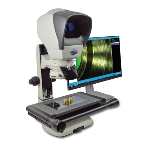
Vision Engineering VE Cam User manual

FM 557119
User guide
VE Cam
Navigaon
instrucons
Contents
list

2
NAVIGATION INSTRUCTIONS
The symbols in the le-hand margin of each page of the manual will enable you to carry out the following funcons:
Thebuonsintextbelowdonotfuncon.Theyareforillustravepurposesonly.
Click on this buon to display the Contents page.
Back one page.
Forward one page.
Back button.
Forward button.
Click this button to print some or all of the document (specic pages can be chosen).
Exit
Click this button to exit the user guide.
PresstheEsckeytodisplaynormalAcrobat©Controls.
Contents
Exit
Contents
Start page

3
SERIAL NUMBER
Unit serial number
Unittype Serialnumber
VE Cam
Stand
S/N
S/N
Exit
Contents
Start page

4
PREFACE
Copyright
Copyright © 2021 Vision Engineering Ltd., Galileo Drive, Send Road, Send,
Woking, Surrey GU23 7ER, UK All Rights Reserved.
Copyright in this document is owned by Vision Engineering Ltd. Any person is
hereby authorised to view, copy, print and distribute this document subject to
the following condions:
The document may be used for informaonal purposes only
The document may be used for non-commercial purposes only
Any copy of this document or poron thereof must include this copyright noce
Revision 1.0, published December 2021 by:
Vision Engineering Ltd.
Galileo Drive
Send Road, Send
Woking, Surrey, GU23 7ER, UK
www.visioneng.com
Disclaimer
This document is provided “as is” without any warranty of any kind, either express
or implied, statutory or otherwise; without liming the foregoing, the warranes
of sasfactory quality, tness for a parcular purpose or non-infringement are
expressly excluded and under no circumstances will Vision Engineering Ltd. be
liable for direct or indirect loss or damage of any kind, including loss of prot,
revenue, goodwill or ancipated savings. All such warranes are hereby excluded
to the fullest extent permied by law.
We have compiled the texts and illustraons as accurately as possible. However,
Vision Engineering Ltd. will not be responsible for the accuracy of the informaon
contained in this document, which is used at your own risk and should not be
relied upon. The informaon included in this manual may be changed without
prior noce.
Exit
Contents
Start page

5
General
Safety
Before using your system for the rst me, please read the Health & safety
secon of the user guide.
Ensure that:
Your system and accessories are operated, maintained and repaired by
authorised and trained personnel only.
All operators have read, understood and observe the user manual, in
parcular the safety regulaons.
Servicing
Repairs may only be carried out by Vision Engineering-trained service
personnel. Only original Vision Engineering spare parts may be used.
Symbols used
Warning!
A potenal risk of danger exists. Failure to comply can cause i) a hazard
to personnel; ii) instrument malfuncon and damage. Please consult the
operang instrucons provided with the product.
Importantinformaon
This symbol indicates important informaon. Please carefully follow the
instrucons or guidelines.
Health & safety
Unauthorisedalteraonstotheinstrumentornon-compliantuseshallinvalidate
allrightstoanywarrantyclaims.
Electrical safety
Disconnect your system from the electrical source before undertaking
any maintenance.
Avoid using any form of liquid near the system.
Do not operate your system with wet hands.
Only use with the power supply unit provided, in case of a lost or
damaged power supply, the correct replacement must be obtained from
Vision Engineering.
Illuminaon safety
Do not look directly at the illuminated LED’s. This may cause damage to
the eyesight.
Environmental consideraons
Avoid large temperature uctuaons, direct sunlight and vibraons.
Ensure electrical components are at least 10cm from walls and
combusble materials.
Posion the system on a rm, rigid and level table.
The equipment should be posioned so that access to the electrical input
connector is always available.
Avoid posioning your system where bright reecons may aect the image.
Exit
Contents
Start page

6
Compliance statements
Vision Engineering and its products conforms to the requirements of the EC
Direcves on Waste Electrical and Electronic Equipment (WEEE) and Restricon of
Hazardous Substances (RoHS).
This product conforms to the UKCA and CE marks, demonstrang that it meets the
requirements of the applicable direcves.
Operator wellbeing
The advanced ergonomic design and construcon of Vision Engineering
products are intended to deliver superior ergonomic performance, reducing
the exeron of the user to a minimum. Depending on the duraon of
uninterrupted work, appropriate measures should be taken to sustain opmal
operator performance. This could include: Opmal arrangement of workplace;
Variaon in task acvity; Training of personnel on workplace ergonomics and
general health and safety principles.
It is important to set-up and opmise your working environment correctly in
order to obtain maximum benet from the advanced ergonomic design of your
system. For more informaon visit: www.visioneng.com/ergonomics
Cleaning
Disconnect your system from the electrical source before cleaning.
Do not use any unsuitable cleaning agents, chemicals or techniques for
cleaning.
Never use chemicals to clean coloured surfaces or accessories with
rubberised parts.
Use a specialist lens cloth to clean opcal surfaces.
Exit
Contents
Start page

7CONTENTS
Contents
SERIALNUMBER
Unit serial number 3
PREFACE
Copyright 4
Disclaimer 4
General 5
Safety 5
Servicing 5
Symbols used 5
Warning! 5
Importantinformaon 5
Health & safety 5
Electrical safety 5
Illuminaon safety 5
Environmental consideraons 5
Operator wellbeing 6
Cleaning 6
Compliance statements 6
INTRODUCTION
Introducon 8
UNPACKING
Unpacking the VE Cam 9
Unpacking the stand 9
ASSEMBLY
Aaching VE Cam to the stand 10
Connecons 10
OPERATION
Physical controls 11
Interfaces 11
Soware controls 11
Menu informaon bar 11
Image manipulaon 12
Soware funcons 12
TECHNICALDATA
Technical data 16
Opcal data 16
TROUBLESHOOTING
Troubleshoong 18
No video 18
No Wi-Fi 18
No Power 18
Unit can not be controlled. 18
Image looks blurred 18
SERVICING
Service record 19
WARRANTY 20
Contents
Exit
Start page

8INTRODUCTION
INTRODUCTION
Introducon
Congratulaons on your selecon of a VE Cam from Vision Engineering. Vision
Engineering Ltd. prides itself in designing and manufacturing products that
make a real dierence to your work.
VE Cam 50 and 80 are the next addions to a line of ground breaking products.
They oer a wide eld of view, small footprint, and ease-of use (with a number
of user set presets) to maximise your producvity.
Exit
Contents
Start page

9UNPACKING
Unpacking the stand
u
Bench stand
v
Allen key
w
SX Microscope bracket
(not used)
x
Power cable
y
Round inserts For substage
(not shown)
u
y
vw
x
UNPACKING
Unpacking the VE Cam
u
VE Cam
v
Mouse (not shown)
Power supply (not shown)
HDMI cable (not shown)
USB sck (not shown)
v
u
Exit
Contents
Start page

10 ASSEMBLY
Connecons
`Connect the power lead supplied to socket u.
`Connect either a touch screen or monitor to the HDMI socket v.
`Use the rear USB ports w to connect a mouse, oponal keyboard, or touch
screen control cable.
`Use the 2 USB connectors x (one each side) for any addional lighng opons
or USB sck during operaon.
AUSBhubcanbeusedwiththesystemshouldmoreUSBsocketsberequired.
TheVECamhoweverwillonlysavetotherstconnectedUSBmemorydevice.
Whenpowerisconnectedtheunitwillpowertostandby.
u
v
w
x
x
ASSEMBLY
Aaching VE Cam to the stand
`Insert the locaon spigot u on the rear of the VE Cam into the receptor v
on the stand.
`Ensure that the spigot is fully inserted, with the VE Cam objecve lens
poinng down, ghten the grub screw w unl the head is secure.
`Alignment can then be adjusted when the VE Cam is operaonal by slightly
loosening the grub screw and ghtening it back up when in the desired posion.
ThefrontvercalseamoftheVECamshouldrunparallelwiththecolumnof
thestandwhenstraight.Howeverthecameracanbemountedatanangleif
required.
u
v
w
Exit
Contents
Start page

11 OPERATION
OPERATION
Physical controls
`Turn the VE Cam on by pressing the On/O buon u on the front of the head.
`Use the slider v for Iris control and w for focus adjustment.
`All other system operaons are soware controlled.
Interfaces
The VE Cam is compable with several interface devices:
You can control the menu via mouse, keyboard, touch screen and the Vision
Engineering keypad.
For informaon on image manipulaon controls please see relevant secon.
w
v
u
Soware controls
`When the VE Cam is turned on, a splash screen will be displayed while the unit
boots up. A screen as below will then be displayed.
`The icons u to the right of the screen can be turned o (see Sliders on page 14).
`The menu informaon bar v displays the current magnicaon and exposure
sengs.
Menu informaon bar
`Click Menu on the menu informaon bar (shown below) to access the
soware funcons (see Soware funcons on page 12).
u
v
Menu 28.8 0
Exit
Contents
Start page

12 OPERATION
Soware funcons
`When Menu is selected from the menu informaon bar, the main menu will be
displayed (see below).
`The following funcons can be selected from the main menu:
u Camera sengs (see page 13)
v Lighng control (see page 13)
w Record a screen image (see page 13)
x Images sengs (see page 13)
y Presets (see page 14)
z Crosshairs (see page 14)
{ Device sengs (see page 14)
Inordertoindicatewhenafunconhasbeenselected,thearrowtoitsrightwill
changefrom to .
Menu
Camera Settings
0
u
v
w
x
y
z
{
Image manipulaon
The live image can be manipulated in several ways:
Mouse
Use the scroll wheel to zoom a live image and once zoomed use the le mouse
buon to pan. Two nger pinch zoom is also supported on mouse pads (if they
oer this feature).
Touch Screen
Two nger pinch zoom is supported via a touch screen. Once zoomed, the live
image can be panned by sliding a nger on the screen.
Vision Keypad
Zoom funconality of the Vision Engineering Keypad is supported.
USB Keyboard
The following keys produce the following:
‘+’+‘CTRL’ Zoom image in
‘-’+‘CTRL’ Zoom image out
‘1’ Zoom image to 1x (fully zoomed out)
‘2’ Zoom image to 1.33x zoom
‘3’ Zoom image to 2x zoom
‘4’ Zoom image to 4x zoom
‘5’ Zoom image to 5x zoom
‘Le’ Pan image le
‘Right’ Pan image right
‘Up’ Pan image up
‘Down’ Pan image down
Exit
Contents
Start page

13 OPERATION
Lighng control
`To adjust the illuminaon level, click on the icon shown above and the lighng
slider will be displayed.
`Click on the slider and use it to adjust the ringlight’s illuminaon to the required level.
Record a screen image
`Click the icon shown above to save the image on screen to a le. File locaon
can be set in the Image sengs menu (internal memory is set by default).
Tosetthepreferencesforasavedimage,seeImagesengsbelow.
Image sengs
`Click on the icon shown above to display the following preferences:
Camera sengs
`Click on the icon shown above to display the opons.
`When any funcon below has been selected and viewed or altered, return to
the main menu by clicking an icon (to open that menu) or navigate using the
back arrow. To close the menu, click on Menu in the menu informaon bar.
Exposure
`Click on the icon shown above to select either manual or automac
exposure.
`If manual exposure is selected, the gain and exposure me
icons will be displayed with their adjustment sliders.
`Click on the appropriate slider and adjust it to the required value.
One buon White Balance
`Place a white object under the camera and click on the icon shown
above to perform a one buon press white balance.
Focus assist on/o
This funcon gives an on screen indicaon indicator to help manually focus
the subject.
`Click on the icon shown above to display two window sizes.
`Click on the window size required. The focus assist will analyse the focus
within the window. The relave focus level is indicated in the focus assist bar.
`Click on the focus slider and use it to alter the focus value. A maximum
value will be reached when the object is in focus. If the object starts to
go out of focus then the value decreases.
Magnier window on/o
`Click on the icon shown above so an area of the screen is magnied 2x
greater than at the current magnicaon. This area can be selected out
of two sizes.
Image le format
`Click on the icon shown above and then select either PNG or JPG as the
format in which the image le will be saved.
Time stamp
`Click on the icon shown above so that a me stamp is displayed in the
corner of the image.
Graphics opon
`Click on the icon shown above to save image with menu over the top or
image with no graphics (other than me stamp if turned on).
File manager
`To select where an image is stored, click on the icon shown above and
then click on . The USB or internal opons will then be displayed.
`Click on the required opon.
Image playback
`To select an image to view on the screen. When clicked a le explorer will
open and the le locaon can be chosen.
`If using a mouse, right clicking on a le will give you the opon to rename
the le using an on screen keyboard (or USB keyboard if aached).
`Saved images can also be deleted.
Exit
Contents
Start page

14 OPERATION
Magnicaon
`Click the icon shown above and then to alter the screen size.
`Click on the slider and use it to adjust the screen size as required.
Display
`Click the icon shown above to show the aspect rao choices.
`Click to select to show the camera in the nave 4:3 format, or to
select the full screen 16:9 rao.
16:9llsthescreenbutlosesasmallamountofimagetopandboom,
decreasingtheeldofviewvercally.
Sliders
`Click the icon shown above to display the dedicated controls that can be acvated to
appear on screen. The controls that can be acvated or deacvated are as follows:
Zoom
(slider)
Lighng (slider)
Magnier (see Magnier window on/o, page 13)
Capture image
Hotkeys P1 to P6. Any preset can be assigned to any of the programmable
keys. The rst 3 hotkeys (P1 to P3) are also available on P1 to P3 of the
Vision Engineering keypad.
When acvated these controls will appear on the right hand side of the screen.
Presets
The current sengs can be saved as one of 10 preset les. These sengs can
then be recalled or cleared as follows:
`Click on the icon shown above to display the 10 presets.
`Select a preset and then click on one of the following icons:
to save seng to the selected preset
to save the current preset to USB
to load the preset from USB into the selected preset
Crosshairs & grids
`To turn crosshairs and grids on or o, or alter their appearance, click on the
icon shown above and proceed as follows:
`Click to change to the following:
Short crosshair
Long crosshair
Course grid
Fine grid
Turned o
`Click to select the required crosshair colour.
Device sengs
`Click the icon shown above to change the following system sengs:
Magnicaon
Display
Sliders
User interface
WIFI
Set up
Exit
Contents
Start page

15 OPERATION
Wi-Fi
`Click on the radial buon next to the Wi-Fi icon to enable a Wi-Fi hotspot
within the device.
`When clicking on the Wi-Fi icon two QR codes will be shown on the screen.
`When scanned with a QR scanner on your mobile device, the rst QR code will
prompt you to connect to the VE Cam’s hotspot (entering the password for you).
Once connected, the second QR code when scanned will prompt you to go to
the local URL where the live image can be streamed.
`Once the portable device is showing the website, the live image playback can be
acvated by pressing the play buon.
`If you do not have a QR code reader then the SSID and password details are
included below the QR code. Once connected, open a Internet browser and
navigate to 192.168.0.1.
TheWi-FiPasswordcanbechangedtoanalphanumericstringcontaining8or
morecharacters.
Set up
Click on the icon shown above to make the following system changes:
Time
Date
Factory reset
Import Sengs - imports a sengs le from a USB memory sck
Export Sengs - Exports the current sengs of the VE Cam to a le on a memory
sck so that they can be ported to another VE Cam or recalled at a later me.
Upgrade – Vision Engineering may provide a soware upgrade for the VE Cam
to enhance the performance of the product. To do this place the
upgrade folder (supplied by Vision Engineering) onto a memory device
and insert the memory device into one of the USB ports on the VE Cam.
When upgrade is selected from the menu the VE Cam will look for the
upgrade le and will prompt with an on screen message to start the upgrade.
User interface
`Click the icon shown above to select a language or the posion of the
informaon bar.
`To select a language, click on Language and click on the required language
from the following list:
English
Deutsch (German)
Français (French)
Español (Spanish)
Italiano (Italian)
Portugues do Brasil (Brazilian/Portuguese)
中文 (Chinese)
日本語 (Japanese)
Русский(Russian)
한국어 (Korean)
`To alter the corner posion of the Informaon bar, click on and select
the required opon from the following list:
Up le
Up right
Down le
Down right
O
Exit
Contents
Start page

16 TECHNICALDATA
Funcon VECam50 VECam80
Maximumsubjectheightwhenmountedtoastand
S240 - Bench Stand with Illuminaon 75mm 90mm
S206 - Boom Stand 87mm 102mm
S241 - Double Arm Boom Stand 230mm 245mm
S242 - Double Arm Boom Stand with Base 375mm 390mm
S207 - Arculated Arm Stand 505mm 520mm
Camerainformaon
Camera resoluon 8Mp 8Mp
Capture resoluon 3280 x 2464 3280 x 2464
Display resoluon 1920 x 1080 1920 x 1080
Opcalresoluon
(Line pairs per mm) 22.63 16
Framerate
Maximum 15 fps 15fps
Monitormountopons Accessory available
Mouseinterface USB USB
Keyboardinterface USB USB
Touchscreencompable Yes Yes
Imagecaptureformats jpg/png jpg/png
Savedimagesizes(MB) 1-3 Mb 1-3 Mb
USBsckcompability FAT32 FAT32
Timestamp DD/MM/YY DD/MM/YY
HH:MM HH:MM
TECHNICAL DATA
Technical data
Opcal data
Funcon VECam50 VECam80
FiledOfView
MinimumMagnicaon
Horizontal FOV 40mm 64mm
Vercal FOV 30mm 48mm
Diagonal FOV 50mm 80mm
Magnicaon using 24” screen 9.97 6.23
Maximummagnicaon
Horizontal FOV 8mm 12.8mm
Vercal FOV 6mm 9.6mm
Diagonal FOV 10mm 16mm
Magnicaon using 24” screen 49.9 31.15
Zoomrao
Digital zoom rao 5:1 5:1
Lensfocustravel 30mm 25mm
Workingdistance
(Distance from front of lens to
subject in focus) 163mm 148mm
Exit
Contents
Start page

17 TECHNICALDATA
Systemweight
VECamSystem Weight
Head weight VE Cam50 = 520g VE Cam80 = 504g
Stand weight (S240) 3.72kg
Total system VE Cam50 =4.24kg VE Cam80 = 4.22kg
Allweightsarenet.
Systempower
Input Output
100-240V AC 50/60Hz 10W
Onlyusewiththesuppliedpowersupply.
Funcon VECam50 VECam80
Menulanguages English
German
French
Spanish
Italian
Brazilian/Portuguese
Chinese
Japanese
Russian
KeyboardShortCuts
F1=P1
F2 = P2
F3 = P3
F4 = up arrow
F5 = down arrow
F6 = Light +
F7 = Light -
F8 = Zoom +
F9 = Zoom -
F10 = Save image
F11 = le arrow
F12 = right arrow
`+’ + `CTRL’ = Zoom image in
`-’ + `CTRL’ = Zoom image out
`0’ + `CTRL’ = Zoom image to 1x (fully zoomed out)
`1’ = Zoom image to 1x (fully zoomed out)
`2’ = Zoom image to 1.33x zoom
`3’ = Zoom image to 2x zoom
`4’ = Zoom image to 4x zoom
`5’ = Zoom image to 5x zoom
`Le’ = Pan image le
`Right’ = Pan image right
`Up’ = Pan image up
`Down’ = Pan image down
Exit
Contents
Start page

18 TROUBLESHOOTING
TROUBLE SHOOTING
Troubleshoong
No video
Check HDMI connecons.
Power buon should be illuminated green
No Wi-Fi
Check that Wi-Fi is enabled in the menu
Scan local Wi-Fi signals. Your VE Cam should be listed.
No Power
Check that jack plug is fully home in the socket.
Check that power buon is red when power is applied.
Unit can not be controlled.
Check that controller is connected into a USB socket on the VE Cam
Image looks blurred
Adjust focus using the ne adjustment of turning the objecve lens
The lens could be dirty. The lens can be cleaned gently with a so, dry cloth. A
damp or course cloth can damage the coang and polished surface on the lens.
NeverlookdirectlyattheLEDlightsourceforanyprolongedperiodofme.
Use only the supplied power supply and inspect the cabling regularly for damage.
VECamcontainsasmallbaerytoenablemeanddatesengstobe
retainedwhiletheunitispoweredo.Shouldthebaeryneedreplacing
pleasecontactyourVisionEngineeringrepresentavewhowillbeableto
adviseyou.
Exit
Contents
Start page

19 SERVICERECORD
SERVICING
Service record
Service Comments Dateofservice Dateofnextservice Company Signature
All product specicaons and data are subject to change without noce
Exit
Contents
Start page

20 WARRANTY
WARRANTY
WARRANTY
This product is warranted to be free from defects in material and workmanship for a period of one year from the date of invoice to the original purchaser.
If during the warranty period the product is found to be defecve, it will be repaired or replaced at facilies of Vision Engineering or elsewhere, all at the opon of
Vision Engineering. However, Vision Engineering reserves the right to refund the purchase price if it is unable to provide replacement, and repair is not commercially
praccable or cannot be mely made. Parts not of Vision Engineering manufacture carry only the warranty of their manufacturer. Expendable components such as
fuses carry no warranty.
This warranty does not cover damage in transit, damage caused by misuse, neglect, or carelessness, or damage resulng from either improper servicing or
modicaon by other than Vision Engineering approved service personnel. Further, this warranty does not cover any roune maintenance work on the product
described in the user guide or any minor maintenance work which is reasonably expected to be performed by the purchaser.
No responsibility is assumed for unsasfactory operang performance due to environmental condions such as humidity, dust, corrosive chemicals, deposion of oil
or other foreign maer, spillage, or other condions beyond the control of Vision Engineering.
Except as stated herein, Vision Engineering makes no other warranes, express or implied by law, whether for resale, tness for a parcular purpose or otherwise.
Further, Vision Engineering shall not under any circumstances be liable for incidental, consequenal or other damages.
Exit
Contents
Start page
Table of contents
Other Vision Engineering Measuring Instrument manuals
Popular Measuring Instrument manuals by other brands

YOKOGAWA
YOKOGAWA VigilantPlant mR20000 Operation guide

TPI
TPI 600 Series instruction manual

FlowLine
FlowLine PodView LI40 Series Quick start quide

PCB Piezotronics
PCB Piezotronics 3500 Series Installation and operating manual

Observator Instruments
Observator Instruments ANALITE NEP160 user manual

Yeasn
Yeasn CCQ-800 user manual
CET
CET PMC-53A quick start guide

Pasco Scientific
Pasco Scientific OS-8537 Instruction manual and experiment guide
Apogee Instruments
Apogee Instruments DLI-400 owner's manual
elmeasure
elmeasure LG 64 Series Programming manual
Hanna Instruments
Hanna Instruments HI 96107 instruction manual
Extech Instruments
Extech Instruments VB450 user guide
