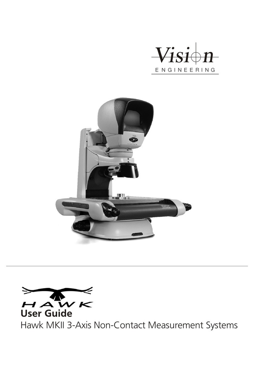
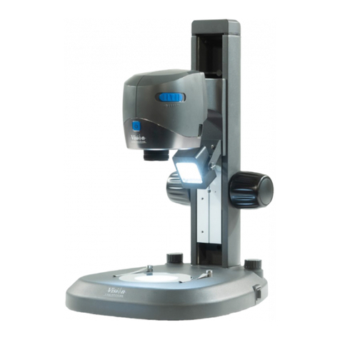
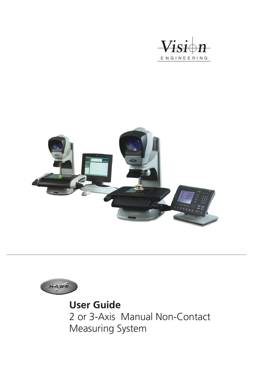
Vision Engineering SWIFT PRO Series User manual

9Swift PRO Duo
9Swift PRO Cam
9Swift PRO Elite
User Guide
Vision Engineering Ltd has been
certified for the quality management
system ISO 9001:2015.
FM 557119
Est. 1958
www.visioneng.com
Swift PRO series of optical and
video measuring systems


General
Intended use of equipment:
Swift PRO provides high accuracy non-contact
measurement of complex manufactured components
and materials.
Safety
Before using your system for the rst time, please read
the Health & safety section of the user guide.
Ensure that:
Your system and accessories are operated, maintained
and repaired by authorised and trained personnel only.
All operators have read, understood and observe the
user manual, in particular the safety regulations.
Cleaning
Disconnect your system from the electrical source
before cleaning.
Do not use any unsuitable cleaning agents, chemicals
or techniques for cleaning.
Never use chemicals to clean coloured surfaces or
accessories with rubberised parts.
Use a specialist lens cloth to clean optical surfaces.
Servicing
Repairs may only be carried out by Vision Engineering-
trained service personnel. Only original Vision Engineering
spare parts may be used.
Symbols used
Warning!
A potential risk of danger exists. Failure to comply can
cause i) a hazard to personnel; ii) instrument malfunction
and damage. Please consult the operating instructions
provided with the product.
Warning of electrical shock hazard
This symbol indicates the presence of electric shock
hazards. Please consult the operating instructions
provided with the product.
Important information
This symbol indicates important information. Please
carefully follow the instructions or guidelines.
Health & safety
Unauthorised alterations to the instrument
or non-compliant use shall invalidate all
rights to any warranty claims.
Electrical safety
Disconnect your system from the electrical source
before undertaking any maintenance.
Avoid using any form of liquid near the system.
Do not operate your system with wet hands.
Heat safety
A dust cover is supplied with your system. Turn off
your system and ensure it has cooled down before
using the dust cover.
Illumination safety
Do not look directly at the illuminated LED’s. This may
cause damage to the eyesight.
Environmental considerations
Avoid large temperature uctuations, direct sunlight
and vibrations.
Ensure electrical components are at least 10cm from
walls and combustible materials.
Position the system on a rm, rigid and level table.
The equipment should be positioned so that access to
the electrical input connector is always available.
Avoid positioning your system where bright reections
may affect the image.
Operator wellbeing
The advanced ergonomic design and construction
of Vision Engineering products are intended to
deliver superior ergonomic performance, reducing
the exertion of the user to a minimum. Depending
on the duration of uninterrupted work, appropriate
measures should be taken to sustain optimal operator
performance. This could include: Optimal arrangement
of workplace; Variation in task activity; Training of
personnel on workplace ergonomics and general
health and safety principles.
It is important to set-up and optimise your working
environment correctly in order to obtain maximum benet
from the advanced ergonomic design of your system. For
more information visit: www.visioneng.com/ergonomics
Compliance statements
Vision Engineering and its products conforms to the
requirements of the EC Directives on Waste Electrical and
Electronic Equipment (WEEE) and Restriction of Hazardous
Substances (RoHS).
All Vision Engineering products conform to the CE mark,
demonstrating that each product meets the requirements
of the applicable EC directives. Where applicable, other
characteristics of the CE directive are implied such as
essential health and safety requirements from all the
directives that applies to its product, including low
voltage directive and the EMC directive.

UNPACKING
1 2 3
Copyright
Copyright © 2017 Vision Engineering Ltd., The Freeman
Building, Galileo Drive, Send, Woking, Surrey GU23 7ER,
UK All Rights Reserved.
Mantis® (1532468), Lynx® (3672061) and Dynascope®
(915579) are registered trademarks of Vision Engineering
Ltd. The use of our trademarks is strictly controlled and
monitored and any unauthorised use is forbidden.
Copyright in this document is owned by Vision
Engineering Ltd. Any person is hereby authorised to
view, copy, print and distribute this document subject to
the following conditions:
The document may be used for informational purposes
only
The document may be used for non-commercial
purposes only
Any copy of this document or portion thereof must
include this copyright notice
Revision 1.0, published June 2017 by:
Vision Engineering Ltd.
The Freeman Building, Galileo Drive, Send,
Woking, Surrey, GU23 7ER, UK
www.visioneng.com
Disclaimer
This document is provided “as is” without any warranty
of any kind, either express or implied, statutory or
otherwise; without limiting the foregoing, the warranties
of satisfactory quality, tness for a particular purpose or
non-infringement are expressly excluded and under no
circumstances will Vision Engineering Ltd. be liable for
direct or indirect loss or damage of any kind, including
loss of prot, revenue, goodwill or anticipated savings.
All such warranties are hereby excluded to the fullest
extent permitted by law.
We have compiled the texts and illustrations as accurately
as possible. However, Vision Engineering Ltd. will not be
responsible for the accuracy of the information contained
in this document, which is used at your own risk and
should not be relied upon. The information included in
this manual may be changed without prior notice.

Contents
System equipment
Stand & objectives 1
Swift PRO Cam 1
Stage 1
Head 2
QC 3000 2
Controller 2
Assembly
Removing the transit protection 3
Attaching the lens mount 3
Objective lens attachment 3
Attaching the LED ringlight 4
Attaching the episcopic illuminator (EPI) 4
Connecting the EPI 4
Stage assembly (150mm x 100mm & 200mm x 100mm) 5
PC system connection 6
QC 3000 connection 6
Stage alignment (video systems only) 7
Securing the stage (150mm x 100mm & 200mm x 100mm) 7
Head attachment 8
Fitting the stage glass 8
Stage glass levelling 9
Anti-glare shield attachment 9
Operation & setup
Main system controls 10
Getting the most from your system 11
Routine maintenance 11
Environmental considerations 11
Substage illumination LED replacement (all models) 12
Graticule tting & adjustment 12
Retrotting the Z axis module 13
Optional riser block 13
Episcopic LED replacement 13
Page

Technical specications
Measuring Stage 14
Measuring Range 14
Height adjustment 14
Encoder Resolution 14
Video Camera 14
Optics (Swift PRO Duo and Elite) 14
Illumination 14
PSU fuse ratings 14
Dimensions 14
Swift PRO Duo and Elite 14
Swift PRO Cam 14
Service & calibration record
Serial numbers 15
Service information 15
Warranty

System equipment
www.visioneng.com/support
1
System equipment
Stand & objectives
Stand
Lens mount
Lens options
Illuminator options
Toolkit
Anti-glare shield
Z Axis upgrade kit
(optional)
Swift PRO Cam
Stage
150mm x 100mm manual stage
OR
200mm x 100mm manual stage

System equipment
www.visioneng.com/support
2
Head
QC 3000
Controller
PC
Monitor
Keyboard and mouse

Assembly
www.visioneng.com/support
3
Assembly
Removing the transit protection
`Remove the two securing screws uand then remove the
transit plate v.
Keep the transit protection for future transport of
your system.
It is highly recommended that you ret the transit
protection whenever you transport your system.
Attaching the lens mount
`Insert the lens mount uup into the focus assembly v
and secure it with the securing grub screw w.
Objective lens attachment
`With the lens mount uin place (see above).
`Place the objective lens vup into the lens mount and
screw it into position.
u
v
v
u
w
v
u

Assembly
www.visioneng.com/support
4
Attaching the LED ringlight
`Locate the LED ringlight uinto position over the lens
mount vand tighten the securing screws w.
For connection details, see page 6.
Attaching the episcopic illuminator (EPI)
`Locate the cone uover the EPI vand secure it with
the grub screw w.
`Locate the EPI into the focus assembly xand secure it
with the grub screw y.
Connecting the EPI
`Insert the appropriate end of the connection lead u
into the EPI connector vand then connect the other
end of the lead wto the connector xon the underside
of the focus assembly y.
u
w
v
y
u
v
w
x
w
x
v
u
y

Assembly
www.visioneng.com/support
5
Stage assembly (150mm x 100mm & 200mm x 100mm)
`Use the stand’s levelling foot uto ensure the base is stable.
`Place the stage on the stand ensuring the retractable foot
(position B4 in diagram vbelow) is fully retracted.
`Check the stand stage mount feet wand the underside of
the stage xare clean and free
of any debris.
`Loosely t the stage bolts yin
position B1, B2 and B3 (also
in diagram v) to a light (nger
tight) tension.
If this is a video system,
do not tighten the stage bolts
as the stage will need to be
aligned (see page 7).
For systems with an optical head
only (no video camera), tighten the
stage bolts in the sequence shown in v
to a torque of 2.8Nm.
`Remove all red transit clamps from the stage.
y
yy
w
u
x
Column
Stage Assembly
B4
B3B1
B2
v

Assembly
www.visioneng.com/support
6
PC system connection
All connectors must be engaged fully and secured.
WARNING: To comply with safety regulations, easy access to the mains socket must be maintained.
QC 3000 connection
All connectors must be engaged fully and secured.
WARNING: To comply with safety regulations, easy access to the mains socket must be maintained.
Y Axis
Z Axis (if fitted)
From camera USB to controller
USB to controller
X Axis Mains in
Stand
Ringlight illumination
Sub-stage, EPI accessory, head power illumination, and AUX connector
From camera USB
Sub-stage, EPI accessory, head power illumination
Ringlight illumination
Mains in
Mains in
X22
X21
X32
Stand
Z Axis
Y Axis
X Axis

Assembly
www.visioneng.com/support
7
u
v
v w
w
w
Stage alignment (video systems only)
`Turn on the system.
`Switch on the PC and follow on screen instructions for crossing reference marks.
`Using the Focus control u, focus on the three horizontal lines in the
centre of the alignment plate attached to the stage.
`Rotate the stage by hand until the horizontal lines are
parallel to the horizontal crosshair on the PC’s screen.
`Use the X axis control vto check reference lines remain
parallel with the crosshair.
Before the alignment plate can be removed the
relevant stage securing procedure should be carried
out.
Securing the stage (150mm x 100mm & 200mm x 100mm)
With the stage assembled (see page 5) and aligned (see above),
secure the stage as follows:
`Being careful not to move the stage,
loosen the oating stage foot
securing screw u.
`Insert and screw in the last stage
bolt v and tighten until nger tight.
`Use the Allen key supplied to progressively
tighten all four screws through the
appropriate holes vand win the alignment
plate in the numbered sequence (shown in the
diagram x below) to a torque of 2.8Nm.
(this is approximately equivalent to bolt touch
down plus 1/8th turn).
`Lightly tighten the oating stage foot securing screw.
u
v
Column
Stage Assembly
B4
B3B1
B2
x

Assembly
www.visioneng.com/support
8
Head attachment
`Lower the head uinto position on the focus assembly
v.
`Insert the head connector winto the head socket x.
`Turn the system on using the mains switch.
`Use the X and Y stage controls yto centre the
alignment
plate zin the viewing screen.
`Turn the head to align the head crosshair with the
alignment plate (see inset {).
`Tighten the securing screw |.
`Remove the alignment plate.
If you need to remove the stage for
any reason, re-attach the alignment
plate and ensure the horizontal
lines are parallel to the horizontal
crosshair before removing the stage.
Fitting the stage glass
`Fit the stage glass u into its recess, taking care to
locate its bevelled edges vagainst the location springs
and on to the supports w.
x
y
{
w
v
|
z
y
u
v
w
ww
w
u

Assembly
www.visioneng.com/support
9
Stage glass levelling
`Use the X axis uand Y axis vcontrols to bring the rear right-
hand corner of the stage glass (xed corner) winto view.
`Use the focus control to bring the glass surface into sharp
focus.
`Use the axis controls to bring the front right-hand corner
into view. Use the relevant adjustable glass support to
bring the surface of the glass into sharp focus.
`Repeat for the remaining 2 corners.
`Repeat the above steps if necessary until all 4 corners are
in focus.
Anti-glare shield attachment
`Slide the anti-glare shield uinto the mounting bracket v.
`Using the screws wand washers x provided, secure into
position with the Allen key (also provided).
`Remove the protective lm from the shield.
w
u
v
wx
v
u

Operation & setup
www.visioneng.com/support
10
Operation & setup
Main system controls
Y axis control
X axis control
Coarse focus control
Fine focus control
On/off switch
Substage light dimmer
Episcopic light dimmer
Ringlight dimmer
Iris control
All desktop control systems congured by Vision
Engineering for this product are set with the
following password:
Vision

Operation & setup
www.visioneng.com/support
11
Getting the most from your system
Routine maintenance
The outside of the instrument should be wiped down
with a damp cloth to remove dirt and dust.
The instrument and accessories should be checked for
loose or damaged components.
When not in use, protect your system with the dust
cover.
Always disassemble the system prior to moving.
Environmental considerations
This equipment is designed for indoor use in the
following conditions:
Up to 2000m altitude
Between 5° and 40°C ambient temperature (10° to
35° recommended limits)
Power supply; 100-120V/ 220-240V, 50/60Hz with
voltage uctuations up to 10% of the nominal voltage
Transient over voltages typically present on the Mains
supply
Maximum relative humidity of 80% for temperatures up
to 31°C decreasing linearly to 50% relative humidity at
40°C.
This system is an accurate, industrial gauging instrument.
To achieve the optimum accuracy and repeatability, the
following considerations should be taken into account:
Position the system on a rm, rigid and level table.
Avoid locating the instrument near to a source of
vibration.
Do not place the instrument close to a radiator or
similar heat source.
Do not place the instrument close to a cold temperature
source such as an air conditioning unit.
Do not position the instrument in direct sunlight, or
where bright reections will affect the image.
The equipment should be positioned so that access
to the mains input connector is always available
If the system you purchased is a Video
product and you purchased your own PC,
Vision Engineering recommend the use of a
powered USB hub for the camera signal.

Operation & setup
www.visioneng.com/support
12
Substage illumination LED
replacement (all models)
`Disconnect the system’s power supply.
`Remove the head, stage and illuminators, carefully
place the unit on its side and remove the 4 LED
cover plate securing screws u.
`Remove the LED cover plate v.
`Remove the LED securing screws wand remove it
from the stand
`Disconnect its ying lead from the connector x.
To install a new LED, reverse of the removal
procedure.
Graticule tting & adjustment
`Undo the securing clip uat the base of the front
cover and lift the cover off.
`Place the graticules v(2 off) into position and
secure them with the lock nuts and grubscrews w
(2 per graticule) and the retaining bolts x.
`To focus and centralize each graticule, loosen the
appropriate retaining knob and move the graticule
up or down to focus. Re-tighten the retaining knob.
`To adjust the graticules, place a known 90º gauge
(slip gauge or crossline) on the stage and focus the
image. Close one eye and locate the crossline on
the corner of the gauge by unlocking and adjusting
the grubscrews. Once the image is located, lock the
grubscrews with the locking nuts.
`Repeat the procedure using the other eye. Make the
adjustment so that the graticules overlay each other.
Note: If the image is uncomfortable to the eyes,
repeat the above procedure.
u
u
w
v
x
u
u
u
v
w
x

Operation & setup
www.visioneng.com/support
13
Retrotting the Z axis module
This procedure should only be carried out by
authorised service personnel.
Please contact your local Vision Engineering
branch for assistance
Optional riser block
This procedure should only be carried out by
authorised service personnel.
Please contact your local Vision Engineering
branch for assistance
Episcopic LED replacement
`Remove the episcopic assembly ufrom the Hawk
and carefully place it on a workbench as shown.
`Pull its power lead vclear of the socket.
`Loosen the 2 securing screws wand pull the LED
assembly xclear of the illuminator.
`The replacement procedure is the reversal of the
above.
u
v
w
v
u
w
x

Technical specications
www.visioneng.com/support
14
Technical specications
Measuring Stage
Precision measuring stage, with factory-set Non-Linear
Error Correction (NLEC) calibration as standard.
(X,Y) Stage accuracy: 5+(6.5L/1000)µm
(Z) Z-axis accuracy 10 µm using controlled conditions
with 200x magnication*
Measuring Range
(X,Y) 200mm x 100mm (10kg maximum load)
(Z) 98mm*
Height adjustment
100mm of height adjustment
Encoder Resolution
X = 1µm Y = 1µm Z = 0.5µm*
Video Camera
High resolution colour CCD video camera
Optics (Swift PRO Duo and Elite)
Patented twin pupil monoscopic, innity corrected
optical system, with pre-centred crossline graticule to
both eyes.
Option of custom designed graticule, pre-centred to
one eye
Magnication Options (System Total)
Quick change magnication options - 10x, 20x, 50x,
100x, 200x
Illumination
Cool, corrected colour temperature LED surface
illumination.
Iris-controlled LED substage illumination.
PSU fuse ratings
T2.5A H (2.5A slow blow (HBC) ceramic 5x20mm fuse)
*3-axis variant only
Dimensions
Swift PRO Duo and Elite
A = 680mm max.
B = 430mm (150mm x 100mm)
515mm (200mm x 100mm)
C = 480mm
Swift PRO Cam
A = 450mm
B = 430mm (150mm x 100mm)
515mm (200mm x 100mm)
C = 480mm
A
C
B
A
C
B
This manual suits for next models
3
Table of contents
Other Vision Engineering Measuring Instrument manuals
