manuals.online logo
Brands
  1. Home
  2. •
  3. Brands
  4. •
  5. Vision
  6. •
  7. Automobile Accessories
  8. •
  9. Vision VAE 738 Mounting instructions

Vision VAE 738 Mounting instructions

VAE-738 V0 1030521 6B1K-73006
Installation & Operation Manual
VAE 738
Wireless Rear View Camera System
-5-
General Information
Thanks for purchasing Vision’s Wireless Rear View Camera System. Vision’s VAE 738
wireless rear view camera system is not only able to enhance your driving experience but
also is designed to reduce the risk of collisions and other potential harm when the vehicle
is reversing.
VAE-738 is using 2.4GHz digital transmission technology to transfer the rear view to your
monitor when backing-up. Meanwhile, the system supports multi-channel which tune
automatically to avoid the signal interference.
Declaration:
Vision’s Wireless Rear View Camera System does not guarantee or promise that the user
will not be in an accident or otherwise not collide with an object. Vision’s Wireless Rear
View Camera System is not intended for use as a substitute for rear-view mirror or for any
other motor vehicle equipment required to be installed by law.
Package Contents
VAE 738 Wireless Rear View Camera System includes:
1PC*Transmitter
1PC*Receiver
1PC* Installation & Operation Manual
1Pack*FittingKit
Specification
Video system: NTSC/PAL (Auto detection)
Video input: 1.0 Vp-p 75Ω
Voltage: 9-32Vdc input
Current consumption TX: ≦300+/-20mA @ 12V
Current consumption RX: ≦200+/-20mA @12V
Digital Transmission: 2.4 GHz, SST 20 channel (FCC/CE)
Dimensions: 113.7(w) x 114.3(h) x 30.8(d) mm
Environmental TX: IP69
Environmental RX: No IP rating
Operating temp: -40℃~+85℃(-40 ℉~+185 ℉)
Wiring Diagram
1. RCA (Yellow) : Camera video connection
2. Red Wire: Power (Connect to reverse signal 12/24Vdc)
3. Black: wire Ground
4. Black/Red wire: Power supply for camera (optional)
1. RCA (Yellow): Video out
2. Red Button: Pairing function button
3. Black Wire: Ground
4. Red Wire: Power (Connect to Reverse signal 12/24VDC)
Installation
Please read the instruction thoroughly prior to installation. Improper installation will void
manufacturer’s warranty. Please note that this package does not include monitor and
camera. Follow the wiring diagram to complete all connection setup. Equipping RX
receiver under dashboard with four screws and fixing TX transmitter in the end of trunk
with four screws as well. When gear is put in reverse position, the transmitter will
automatically power on.
Operation
When gear is in reverse position, monitor display rear view automatically which help
drivers identify an object or a person behind a car and prevent damages from unwanted
accidents.
-1-
-2-
-1-
Trouble Shooting
Pairing is not necessary as the unit has been paired by Vision before shipping, so under
normal circumstance, customer can see rear view clearly after installation. When it
malfunctions, there are number of ways to troubleshoot:
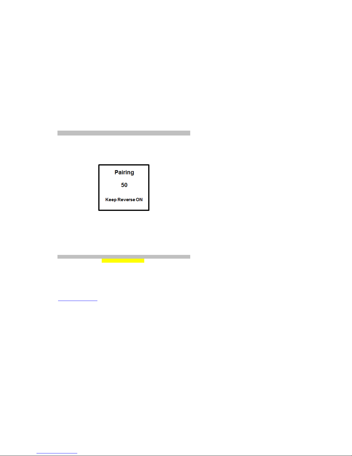
1. If user purchase new transmitter for instead of original one, then please try to pair
the system by pressing “Red Button on transmitter for 2 seconds, the screen will show
the system is in pair mode and start to countdown from 50 seconds.
Once rear view can be transferred to monitor which means user have completed
paring successfully.
2. If monitor shows “No Video Signal” or fails to display, user may check the wire to
make sure the wire is connected correctly or camera is in good condition.
3. If monitor shows “No Signal”, user may check whether the wires are connected
correctly and make sure the camera is able to receive power from vehicle’s electrical
supply system. Or consumer can contact with customer service to check if any
damage occurs.
Limited Warranty
Vision Guarantees that every wireless door/window sensor is free from physical defects in
material and workmanship under normal use for one year from the date of purchase. If
the product proves defective during this one-year warranty period, Vision will replace it
free of charge. Vision does not issue any refunds. This warranty is extended to the
original end user purchase only and is not transferable. This warranty does not apply to :
(1) damage to units caused by accident, dropping or abuse in handling, or any negligent
use; (2) units which have been subject to unauthorized repair, taken apart, or otherwise
modified; (3) units not used in accordance with instruction; (4) damages exceeding the
cost of the product; (5) transit damage, initial installation costs, removal cost, or
reinstallation cost. For information on addional devices, plesae visit us at
www.visionsecurity.com.tw
Federal Communication Commission Interference Statement
This equipment has been tested and found to comply with the limits for a Class B digital
device, pursuant to Part 15 of the FCC Rules. These limits are designed to provide
reasonable protection against harmful interference in a residential installation.
This equipment generates, uses and can radiate radio frequency energy and, if not
installed and used in accordance with the instructions, may cause harmful interference to
radio communications. However, there is no guarantee that interference will not occur in a
particular installation. If this equipment does cause harmful interference to radio or
television reception, which can be determined by turning the equipment off and on, the
user is encouraged to try to correct the interference by one of the following measures:
. Reorient or relocate the receiving antenna.
. Increase the separation between the equipment and receiver.
. Connect the equipment into an outlet on a circuit different from that to which the receiver
is connected.
. Consult the dealer or an experienced radio/TV technician for help.
FCC Caution: To assure continued compliance, any changes or modifications not
expressly approved by the party responsible for compliance could void the user's
authority to operate this equipment. (Example - use only shielded interface cables when
connecting to computer or peripheral devices).
FCC Radiation Exposure Statement
This equipment complies with FCC RF radiation exposure limits set forth for an
uncontrolled environment. This equipment should be installed and operated with a
minimum distance of 20 centimeters between the radiator and your body.
This transmitter must not be co-located or operating in conjunction with any other antenna
or transmitter.
The antennas used for this transmitter must be installed to provide a separation distance
of at least 20 cm from all persons and must not be co-located or operating in conjunction
with any other antenna or transmitter.
This device complies with Part 15 of the FCC Rules. Operation is subject to the following
two conditions:
(1) This device may not cause harmful interference, and (2) This device must accept any
interference received, including interference that may cause undesired operation.
-3- -4-

Popular Automobile Accessories manuals by other brands

Reely TRX-4 operating instructions

Reely

Reely TRX-4 operating instructions

Cequent Performance Products CQT76046 installation instructions

Cequent Performance Products

Cequent Performance Products CQT76046 installation instructions

Steinhof O-136 FITTING AND OPERATION MANUAL

Steinhof

Steinhof O-136 FITTING AND OPERATION MANUAL

Brodit ProClip 854590 installation instructions

Brodit

Brodit ProClip 854590 installation instructions

iDataLink maestro Rr install guide

iDataLink

iDataLink maestro Rr install guide

Vision Systems VS55020 user manual

Vision Systems

Vision Systems VS55020 user manual

Canyon C-02 quick guide

Canyon

Canyon C-02 quick guide

Crux RVCCH-75 installation guide

Crux

Crux RVCCH-75 installation guide

JL Audio Stealthbox SB-J-JL4DDRV/10TW1-2 installation guide

JL Audio

JL Audio Stealthbox SB-J-JL4DDRV/10TW1-2 installation guide

wtw spectroFlex Car Adapter operating manual

wtw

wtw spectroFlex Car Adapter operating manual

Dobinsons BU59-3506 installation guide

Dobinsons

Dobinsons BU59-3506 installation guide

Curt Manufacturing 13203 installation instructions

Curt Manufacturing

Curt Manufacturing 13203 installation instructions

blueLOGIC BMW01 manual

blueLOGIC

blueLOGIC BMW01 manual

Ranger design 3068-DL installation guide

Ranger design

Ranger design 3068-DL installation guide

Volvo 31285547 installation instructions

Volvo

Volvo 31285547 installation instructions

Whispbar K434W Fitting instructions

Whispbar

Whispbar K434W Fitting instructions

Exposed Racks 8-00-9605 installation guide

Exposed Racks

Exposed Racks 8-00-9605 installation guide

Brink 6484 Fitting instructions

Brink

Brink 6484 Fitting instructions

manuals.online logo
manuals.online logoBrands
  • About & Mission
  • Contact us
  • Privacy Policy
  • Terms and Conditions

Copyright 2025 Manuals.Online. All Rights Reserved.