visiplex VS4820 User manual
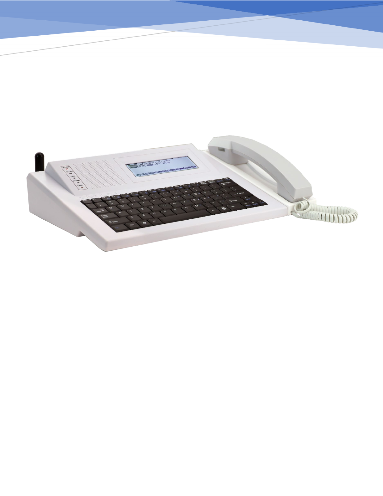
VS4820
User Manual
Ver 1.001
Visiplex
www.visiplex.com

1
Table of Contents
Introduction ...............................................................................................................................................................................................2
Wireless System Architecture ....................................................................................................................................................................2
Event Controlled Devices....................................................................................................................................................................... 4
Event Triggering Sources .......................................................................................................................................................................5
VS4820 Inputs, Outputs and Accessories................................................................................................................................................... 6
Main Paging Screen.................................................................................................................................................................................... 8
Event Selection Screen...............................................................................................................................................................................8
Activity Report Screen ............................................................................................................................................................................... 9
System Status Screen .................................................................................................................................................................................9
System Setup Menu .................................................................................................................................................................................10
Add/Edit Event.....................................................................................................................................................................................11
Wireless PA Speaker Event.............................................................................................................................................................. 11
Tone/Voice/Bell Alert Event............................................................................................................................................................12
Beacon Light Event.......................................................................................................................................................................... 13
LED Message Board Event............................................................................................................................................................... 14
Corridor Light Event ........................................................................................................................................................................15
Two-Way Intercom Station Event ................................................................................................................................................... 16
Two-Way Radio Event .....................................................................................................................................................................17
Digital Pager Event ..........................................................................................................................................................................18
Dial Out Voice Message Event ........................................................................................................................................................19
SMS text Message Event ................................................................................................................................................................. 19
Multimedia Alert Event ...................................................................................................................................................................20
Sequential Event Group ..................................................................................................................................................................21
Radio TX/RX Setup ...............................................................................................................................................................................22
System Configuration .......................................................................................................................................................................... 23
Clock/Time Sync Setup ........................................................................................................................................................................25
Panic Buttons Setup.............................................................................................................................................................................26
Alarm Inputs Setup..............................................................................................................................................................................27
Message Board Default Setup .............................................................................................................................................................28
Database Management .......................................................................................................................................................................29
Event/Bell Schedule Setup...................................................................................................................................................................31
Pre-Programmed Voice Messages.......................................................................................................................................................32
Activation Plans ................................................................................................................................................................................... 32
FM Radio Configuration....................................................................................................................................................................... 33
SMS LTE Modem Setup........................................................................................................................................................................ 34

2
Introduction
The VS4820 Wireless Paging Base Station offers a cost-effective way to implement an urgent wireless communication
solution for commercial applications, such as,emergency mass notification, voice & data paging, 2-way intercom
communication, facility-wide audio/visual alerts and SMS text notifications.
With its built-in database, the VS4820 offers users the ability to program up to 1,000 automatic or manually initiated
events that can wirelessly activate a single or group of:
•Wireless PA speakers for playback of pre-programmed voice messages or live-voice announcements
•Send text messages to wireless LED message boards for highly visible public notifications
•Communicate with facility-wide wireless 2-way intercom stations
•Initiate on-time, schedule-based, break/shift bell alerts for improved productivity
•Activate and control wireless beacon lights for public visual alerts
•Send SMS text messages to cell phones for instant event notification
•Synchronize all on-site wireless analog/digital clocks to one accurate time
The VS4820 provides users with the capability to communicate with Visiplex wireless panic buttons. A received panic
button call can instantly activate a pre-defined event, such as,text messaging, voice message playback, visual alert
activations, etc.
Equipped with a built-in commercial band radio transmitter, the VS4820 is ideal as an all-in-one wireless paging solution.
This solution provides full RF coverage to communicate and activate devices for up to 1,000′. When a longer range is
needed, such as multi-building applications, Visiplex offers medium or high-power radio transmitters/repeaters that can
extend the radio signal range to a multi-mile radius, essentially covering any type of installation.
The VS4820 offers additional features and options, such as,an integrated SMS modem for text messaging and alerts,
dial-in phone access for remote event activation, a serial port for integration with a local building fire alarm system, a
built-in Wi-Fi module for interfacing with a local network, hard-wired alarm inputs and a uniquely designed paging
handset for improved voice communication and privacy.
Wireless System Architecture
The Visiplex product line offers all the needed components to design and implement a variety of wireless solutions
ranging from a simple break bell system to large, multi-building voice & data paging system. Some of the Visiplex
products that can trigger or be controlled by the VS4820 are:
•VS26xx – Wireless PA speakers with integrated beacon light and LED message board options.
•VNS24xx – Wireless intercom stations for two-way voice communications and voice messaging.
•VNS16xx – Wireless LED message boards for text/time display and voice messaging option.
•VNS272x – Wireless multi-color, LED beacon lights for high visibility alerts.
•VNS271x – Wireless multi-color, LED corridor lights for visual status indications & alerts.
•TS4xxx – Wireless synchronized, analog clocks for facility-wide, accurate time display.
•CT15x – Wall Mounted, wireless panic buttons for a facility-wide event triggering.

3
•CT10x – Portable/wearable, wireless panic buttons for instant event activations.
•VP4 – Digital alphanumeric pager for instant personnel notifications.

4
VS4820 Wireless Paging Base Station - Offers user-programmable event database, where each event can be initiated
manually from the unit keyboard or automatically from multiple sources,such as,wireless panic buttons, alarm inputs,
phone lines, serial ports and audio inputs. Each event can be programmed to wirelessly activate a single or group of
Visiplex wireless products,such as: wireless PA speakers, intercom stations, LED message boards, visual alerts, clocks
and can also send text or voice messages to phones.
External Radio Transmitter/Repeater - Equipped with a built-in commercial band radio transmitter, the VS4820 is ideal
as an all-in-one wireless paging solution. This solution provides full RF coverage to communicate and activate devices for
up to 1,000′. When a longer range is needed, such as multi-building applications, Visiplex offers medium or high-power
radio transmitters/repeaters that can extend the radio signal range to a multi-mile radius, essentially covering any type
of installation.
Event Controlled Devices
Wireless Indoor/Outdoor PA Speakers – A variety of wireless PA speakers for playback of pre-programmed
voice messages, live-voice announcements, and break bell alerts. Some Visiplex speakers come with unique add-
on features,such as,integrated, multi-color beacon lights or an LED message board for enhanced visibility when
needed.
Wireless 2-Way Intercom Stations – The VS4820 offers 2-way communication with facility-wide wireless
intercom stations. These intercom stations can also be used for PA voice messaging and break bell alerts.
Wireless LED Message Boards – Wireless text messaging to LED message boards for highly visible public
notifications and public alerts. In addition, these message boards can provide time viewing and offer unique
features, such as, integrated PA speakers and power backup batteries.

5
Wireless Visual Alert Devices –Multi-Color LED beacon and corridor lights that can be wirelessly activated and
controlled from the VS4820 to provide high intensity warning lights and status indications.
Wireless SMS Text messaging & Voice Notification –When equipped with the LTE modem and/or telephone
interface, the VS4820 can send instant SMS text messages to pre-defined cell phones or dial out to playback a
pre-recorded voice message.
Wireless Time Synchronized Clocks –The VS4820 can be set to send a periodic time synchronization signal to a
variety of wireless analog and digital clocks that provide one accurate time facility-wide.
Wireless 2-way Radios & Pagers – The VS4820 can be equipped with the ability to communicate with 2-way
radios, to receive calls or send automatic pre-programmed voice messages. Sending text messages to digital
alphanumeric pagers can be done from the unit keyboard or as result of a pre-programmed event.
Event Triggering Sources
Wireless Panic Buttons – Visiplex offers a variety of wearable, portable or wall-mounted wireless panic buttons
for instant alerts. Panic button alerts are received by the VS4820 and can then instantly activate a pre-defined
event, such as text messaging, voice message playback, visual alert activation, etc.
Hard Wired Event Trigger Sources – The VS4820 can initiate a pre-programmed event from a dial-in phone line,
serial port communication with other in-house systems such as Fire Alarm or Access Control, integrated hard-
wired alarm inputs, voice-activated messaging by an external audio source, a desktop microphone, etc.
Keyboard – The VS4820 keyboard provide the user with the ability to activate any single or group of events,
while being able to make provisional changes to event parameters, operation mode and text message,or issue
real time voice announcements.

6
VS4820 Inputs, Outputs and Accessories
1. On-Off Power Switch – Main power switch
2. DC Power Input –DC power supply input, 12VDC 3Amp
3. Handheld/Microphone Input –RJ-9 connector for external desktop microphone or handset.
4. USB Input –USB Type-B connector for PC programming and control.
5. Phone Line –RJ-11 input for analog (POTS) telephone line.
6. RS-232 Port– RJ-45 Serial port connection for interfacing with other computerized systems.
7. Audio Input – RCA audio input for external source integration and voice activated events.
8. Audio Output – RCA audio output for integration with external sources and amplified speaker.
9. Alarm Inputs – RJ-45 connector to provide one common line and 7 external alarm inputs.
10. External Radio – RJ-45 connector for interfacing with external digital paging transmitter.
11. TX Output – BNC RF-Out antenna connector for the unit integrated radio transmitter.
12. Keyboard – Full size keyboard.
13. Handset with PTT – VS3017 Handset package for improved voice clarity and privacy.
14. LCD Display – Graphic LCD display with backlight.
15. Built-In Microphone– Integrated microphone for 2-way communication and PA announcements.
16. Internal Speaker – Built-in speaker for 2-way voice communication.

7
17. Radio TX Antenna – BNC connector for the VS4820 built-in radio transmitter.
18. Power On – LED indicator for unit activity status.
19. Radio TX/RX – LED indicator for the unit radio reception and transmission activity.
20. Call Status – LED indicator that monitor panic buttons activity and call placements.
21. Phone Line – LED indicator to show the status of phone line during dial in & out activity
22. CAPS – LED indicator for the keyboard CAPS Lock status.
23. LTE/GPS Antenna – SMA antenna connector for the LTE modem or GPS receiver module options.
24. Wi-Fi Antenna – SMA antenna connector for the built-in Wi-Fi option.
25. RX Antenna – SMA antenna connector for the built-in radio receiver.

8
Main Paging Screen
This VS4820 Main Paging screen is designed to help users to instantly trigger pre-programmed events, make live voice
announcements, answer incoming call from wireless intercom stations and monitor panic buttons activity. From this
screen a user can activate special system functions using key combinations and function buttons. To activate/send an
event, the user simply enters the 3 digits ID number of the selected event into the EVENT field at the left top of the
screen. The Status Line at the bottom of the screen,is showing the most common functions that are available to the
user: [F1] to select an event from a list of all active events, [F2] to display the latest system activity and [F9] to access the
System Setup Menu.
Here is a list of all functions that are available to the user from the Main Paging screen:
[F1] – Event List, shows a list of all available events for user selection and activation (see Event Selection Screen).
[F2] – Activity Log, display the latest events and system paging activities (see Activity Report Screen)
[F7] – Volume Down, lower the speaker level.
[F8] – Volume Up, Raise the speaker volume.
[F9] – Select System Setup Menu (requires administrator password).
[F12] – Clears the VS4820 Call indicator and all active wireless panic buttons calls.
[Fn]+[F1] – Sends the current Time Mode to wireless LED message board (see System Setup Menu - Message Board
Setup).
[Fn]+[F2] – Sends the current Marquee Message Mode to wireless LED message boards (see System Setup Menu -
Message Board Setup).
[Fn]+[F3] – Sends FM radio activation to wireless PA speakers (see System Setup Menu – FM Radio Configuration).
[Fn]+[F4] – Sends FM radio de-activation to wireless PA speakers (see System Setup Menu – FM Radio Configuration).
[Fn]+[F5] – Display the System Status screen (see System Status Screen).
[Fn]+[F9] – Mute the VS4820 speaker
[Fn]+[F10] – Sync the VS4820 base station time to wireless cell time (if SMS Modem option is installed).
[Fn]+[F11] – Initiate periodic time sync signal transmissions to clocks and LED message boards.
[Fn]+[F12] – Pause time sync signal transmissions to clocks and LED message boards.
Event Selection Screen
Use the Up/Down arrow keys and [PgUp]/[PgDn] keys to select specific event from the list and simply activate the event
by hitting the [Enter] key. Events marked with ■status are events that been programmed to require additional user

9
input and confirmation before the event can be activated. Events that are marked with ►status are programmed as
auto mode events that when selected, will be activated instantly without any additional user input.
Activity Report Screen
The Activity Report screen provide the user with the ability to view the latest event activations and system paging
activity. When selected, the screen will display a list of events with information regarding the event ID, name, time &
date.Use the Up/Down arrow keys and [PgUp]/[PgDn] keys to select event from the list.
Hitting the [Enter] key to select specific event, will open another window that will display the full details of that event
activation.
The detailed information includes the event ID, event name, the source of the activation (unit keyboard, serial port,
panic button, etc.), the exact time and the encoded message data that has been transmitted.
System Status Screen
The System Status screen provides a review of the VS4820 hardware configuration, interface setup and unit specific
information.

10
SN – Shows the unit serial number.
S. Port – Indicates the current RS-232 serial port protocol. The protocol and serial port functionality can be selected by
the administrator to match the right interface with external equipment or electronic systems.
USB – Indicates the current USB serial communication protocol. This protocol can be selected by the administrator to
match the right PC interface for monitoring and control.
Radio – Displays the selected paging radio used by the system. From the System Setup Menu, the user can select the
internal or external radio that is being used for the system wireless paging activities.
RX – Displays the current receive frequency of the system radio.For example: 452.8625 MHz
TX – Displays the current transmit frequency of the system radio. For example: 462.7500 MHz
Phone – Shows the status of the system phone line interface. If integrated and functional the status will be INST,
otherwise it will be N.A.
SMS Modem – Shows the status of the system LTE modem interface for text messaging. If integrated and functional the
status will be INST, otherwise it will be N.A.
WiFi – Shows the status of the system Wi-Fi network interface. If integrated and functional the status will be INST,
otherwise it will be N.A.
GPS RX – Shows the status of the system GPS receiver. If integrated and functional the status will be INST, otherwise it
will be N.A.
ALARMS – Indicates the status of the system’s seven alarm inputs. When any of the alarm inputs are active, its status
indication will change from ‘0’ to ‘1’. This field can help with diagnostic and testing of the alarm inputs
functionality.
VER – Shows the unit firmware version.
The user can use the [F9] button to refresh the screen and alarm inputs status or hit the [ESC] key to return to the Main
Paging Screen.
System Setup Menu
Accessing the System Setup Menu, requires an administrator level access and entering a password. This password can be
changed or disabled from the System Configuration menu. By default, the user will be asked to enter a password. The
factory default password is ‘PASSWORD’.
After entering the right password, the System Setup Menu will be displayed.

11
This menu lets the user configure all the parameters and functions of the VS4820, create and edit events, manage
databases, and more. Selecting a submenu item from the list can be done by scrolling using the Up/Down arrow keys
and hitting the [Enter] key, or by entering a 2-digit number that associate with the selected submenu.
Add/Edit Event
The Add/Edit Event submenu lets the user create new or edit existing system events. When selected, a list of existing
events will be displayed on the screen.
To edit an existing event, the user can use the up/down arrow, [PgUp], [PgDn] & [Enter] keys to select or enter the 3-
digit event ID number, results with the selected event information being displayed on the screen.
To create a new event, an unused 3-digit ID number should be entered. If the entered ID has not been used before, a
popup window will appear on the screen to let the user to select the type of event.
Using the Up/Down arrow keys, the user can choose the type of event and press [Enter] to select it, resulting with the
event editing screen being displayed with default parameters values.
Wireless PA Speaker Event
The Wireless PA Speaker event type was designed to initiate live voice announcements or playback of pre-recorded
voice messages from the VS4820 data storage. This event type activates and controls any Visiplex product that is
equipped with the ability to receive live voice transmissions and drive PA speakers, such as the VNS26xx wireless PA
speakers, VNS16xx LED message boards and the VNS24xx 2-way intercom stations.

12
Code – A unique 7-digit activation code that can activate a single or group of wireless PA speakers. Usually, Visiplex
products include up to 8 user-programmable activation codes, that provide individual speaker activation or as
part of up to 7 groups/zones. Use the keyboard numeric keys to enter/edit the activation code.
Level – Setup the PA speaker audio level for this event. Use the Up/Down arrow keys to select one of four audio levels:
Low, Medium, High or Maximum level.
Timeout – Select the maximum duration that the PA speaker will stay open after activation, before timing out and
closing (unless the VS4820 base station ends the PA session first). Use the Up/Down arrow keys to select the
preferred timeout value.
Mode – Select the PA activation mode between Live audio or playback of one of pre-programmed voice messages stored
on the unit. Use Up/Down arrow keys to select the mode or pre-programmed (01-99) voice message.
Pre-Tone – Each of Visiplex products that comes with PA voice capabilities, include built-in alert tones, that can be used
to get the public attention, before the actual PA message announcement starts. To use this option, use the
Up/Down arrow keys to select the alert ID, and if needed the number of times the alert will repeats
Name – A descriptive title/name for the event that will help identify it from other events. Type in the description and hit
[Enter] to move to next field.
Auto – Enable/disable the event activation style. If enabled, the event will be initiated instantly, (when activated)
without any additional user input or confirmation. If the Auto mode is disabled, the user will be able to
temporarily change the PA message audio level and confirm the activation, before any data is being transmitted.
TX Channel – Select the transmitter RF channel for this event, if other than the default channel, in cases where the
VS4820 base station operates on more than one frequency.
Use the Left/Right arrow keys to navigate between the fields. Use [F5] to save any changes, [F9] to delete the event (if
editing an existing event) and hit the [ESC] key to exit the screen back to the previous menu.
Tone/Voice/Bell Alert Event
The Tone/Voice/Bell Alert event type was designed to initiate the playback of pre-recorded tone & voice alerts to
Visiplex products that are equipped with that feature such as the VNS26xx wireless PA speakers, VNS16xx LED message
boards and the VNS24xx 2-way intercom stations. This is the preferred event type to associate with a break bell schedule
to initiate a bell tone alert at specific times and days.

13
Code – A unique 7-digit activation code that can activate a single or group of wireless PA speakers. Usually, Visiplex
products include up to 8 user-programmable activation codes, that provide individual speaker activation or as
part of up to 7 groups/zones. Use the keyboard numeric keys to enter/edit the activation code.
Tone – Select the tone/bell alert ID number (01-99), using the Up/Down arrow keys.
Level – Setup the PA speaker audio level for this event. Use the Up/Down arrow keys to select one of four audio levels:
Low, Medium, High or Maximum level.
Length – If the selected tone duration is too short, its length can be adjusted using this parameter.
Repeats – Select the number of times the tone/alert should be repeated, if any.
Pre-Tone – Select another optional tone alert to be played before the event main tone (to get public attention). To use
this option, use the Up/Down arrow keys to select the pre-tone alert ID (01-09).
Name – A descriptive title/name for the event that will help identify it from other events. Type in the description and hit
[Enter] to move to next field.
Auto – Enable/disable the event activation style. If enabled, the event will be initiated instantly, (when activated)
without any additional user input or confirmation. If the Auto mode is disabled, the user will be able to
temporarily change the tone playback audio level, number of repeats, and confirm the activation, before any
data is being transmitted.
TX Channel – Select the transmitter RF channel for this event, if other than the default channel, in cases where the
VS4820 base station operates on more than one frequency.
Use the Left/Right arrow keys to navigate between the fields. Use [F5] to save any changes, [F9] to delete the event (if
editing an existing event) and hit the [ESC] key to exit the screen back to the previous menu.
Beacon Light Event
The Beacon Light event type is designed to control and activate wireless beacon lights to help indicate to staff, visitors,
and employees about specific emergency situations, production line alerts, or severe weather conditions.
The Visiplex VNS2620 & VNS2640 and VNS272x multi-color LED beacon light capabilities, are the type of products that
can be controlled with this event type.
Code – A unique 7-digit activation code that can activate a single or group of wireless beacon light devices. Usually,
Visiplex products include up to 8 user-programmable activation codes, that provide individual activation or as
part of up to 7 groups/zones. Use the keyboard numeric keys to enter/edit the activation code.
Mode – Light signaling mode. Select one of five modes: Light Off, Light On, Flash 1 (slow flash), Flash 2 (fast flash) and
Strobe. Select the preferred mode using the Up/Down arrow keys.
Color – Select the beacon light color. There are 5 basic (Amber, Green, Blue, White & Red) and 4 user-programmable
colors to choose from. Select the preferred color using the Up/Down arrow keys.

14
Brightness – Setup the beacon light brightness for this event. Use the Up/Down arrow keys to select one of 9 brightness
levels.
Tone – Select a tone alert mode, to provide audible indication when the beacon light is activated or deactivated. Use the
Up/Down arrow keys to select one of 9 tone alert modes.
Timeout – Set the length of time the beacon light will stay on after activation. Enter 5 digits number to setup the
timeout total number of seconds or ‘00000’ when no timeout is required (beacon light will stay on until turned
off by another event).
Name – A descriptive title/name for the event that will help identify it from other events. Type in the description and hit
[Enter] to move to next field.
Auto – Enable/disable the event activation style. If enabled, the event will be initiated instantly, (when activated)
without any additional user input or confirmation. If the Auto mode is disabled, the user will be able to
temporarily change beacon light mode, color and confirm the activation, before any data is being transmitted.
TX Channel – Select the transmitter RF channel for this event, if other than the default channel, in cases where the
VS4820 base station operates on more than one frequency.
Use the Left/Right arrow keys to navigate between the fields. Use [F5] to save any changes, [F9] to delete the event (if
editing an existing event) and hit the [ESC] key to exit the screen back to the previous menu.
LED Message Board Event
The wireless LED Message Board event type is designed to control and activate Visiplex alphanumeric message boards
such as the VNS16xx series of LED message boards or the VNS2640 wireless speaker (with integrated LED display). These
LED message boards offers many features, parameters, and text viewing options that can be customized by the user
with each individual event or globally in the Message Board Default Setup menu.
Code – A unique 7-digit activation code that can activate a single or group of wireless LED message boards. Usually,
Visiplex products include up to 8 user-programmable activation codes, that provide individual activation or as
part of up to 7 groups/zones. Use the keyboard numeric keys to enter/edit the activation code.
Slot – Text message slot selection. Each Visiplex LED message board can display up to 99 different messages by assigning
a screen time slot to each message and keep rotating the displayed messages until they reach their timeout or
cleared by another event. Selecting ANY slot mode will write the event text message into the next available
free time slot to be displayed, in rotation, with other messages on the screen. Selecting any slot values from 01-
99 will write the event text message into a specific time slot on the display (overwriting other messages, if they
exist). Setting the slot to Clear Display will send a clear all command to the message board clearing all slots and
display screens. Select the preferred slot number/mode using the Up/Down arrow keys.
Slot Time – Select the slot time length for this event. When rotating with other messages, the user can set the message
screen time (5-20 seconds) for this specific event activation. If there are no other messages on the screen, the
slot time will be ignored, and the message will be displayed until timed out or cleared. If the event Slot was set

15
in the previous field to specific slot number (01-99), you can set the slot time value to Clear Slot, so this event
will be used to clear a specific slot on the message board. Select the preferred slot time or mode using the
Up/Down arrow keys.
Name – A descriptive title/name for the event that will help identify it from other events. Type in the description and hit
[Enter] to move to next field.
Font – Select the preferred text font style & size this event. Use the Up/Down arrow keys to select one of 16 font styles.
See the VNS16xx/VNS2640 user manual for full description of all available font styles.
Format – Select the preferred text display formats for this event. Use the Up/Down arrow keys to select one of 16 text
formats.See the VNS16xx/VNS2640 user manual for full description of available text formats.
Timeout – Set the length of time the message will stay on the screen. Enter 5 digits number to setup the timeout total
number of seconds or ‘00000’ when no timeout is required (message will stay on the screen until cleared by
another event).
Align – Select the text line alignment. Use the Up/Down arrow keys to select Left, Center or Right.
Flash – Enable or disable the text flash mode. Use the Up/Down arrow keys to select.
Yloc – Select the vertical location of the text line on the screen for this event. Depends on the selected font size & style,
the user can select the exact vertical location of the text line, for example to vertically center the line on the
screen. Use the Up/Down arrow keys to select one of 10 values (0 – top of the screen).
TX Channel – Select the transmitter RF channel for this event, if other than the default channel, in cases where the
VS4820 base station operates on more than one frequency.
Auto – Enable/disable the event activation style. If enabled, the event will be initiated instantly, (when activated)
without any additional user input or confirmation. If the Auto mode is disabled, the user will be able to
temporarily add/edit the event text message and confirm the activation before any data is being transmitted.
Message – Text message field. Enter here the text message for this event. Hit the [Del] key to clear the screen and the
[Enter] key when done typing.
Use the Left/Right arrow keys to navigate between the fields. Use [F5] to save any changes, [F9] to delete the event (if
editing an existing event) and hit the [ESC] key to exit the screen back to the previous menu.
Corridor Light Event
The Corridor Light event type is designed to control and activate the Visiplex VNS2710 wireless corridor light fixture that
is being used to help indicate to staff about specific call status, especially when used in assisted living facilities.
Code – A unique 7-digit activation code that can activate a single or group of wireless corridor light devices. Usually,
Visiplex products include up to 8 user-programmable activation codes, that provide individual activation or as
part of up to 8 groups/zones. Use the keyboard numeric keys to enter/edit the activation code.

16
Mode – Light signaling mode. Select one of five modes: Light Off, Light On, Flash 1 (slow flash), Flash 2 (fast flash) and
Strobe. Select the preferred mode using the Up/Down arrow keys.
Color – Select the corridor light lens color. There are 5 basic (Amber, Green, Blue, White & Red) and 4 user-
programmable colors to choose from. Select the preferred color using the Up/Down arrow keys.
Brightness – Setup the corridor light brightness for this event. Use the Up/Down arrow keys to select one of 9 brightness
levels.
Lens – The VNS2720 equipped with four independent lenses that each can be activated with a specific color and mode.
This field let the user select a specific lens (or ALL to apply to all lenses) to be controlled with this event. Use
the Up/Down arrow keys to select 1-4 lens number or ALL for all lenses.
Timeout – Set the length of time the corridor light will stay on after activation. Enter 5 digits number to setup the
timeout total number of seconds or ‘00000’ when no timeout is required (corridor light will stay on until turned
off by another event).
Tone – Select a tone alert mode, to provide audible indication when the corridor light is activated or deactivated. Use
the Up/Down arrow keys to select one of 9 tone alert modes or None to disable.
Name – A descriptive title/name for the event that will help identify it from other events. Type in the description and hit
[Enter] to move to next field.
Auto – Enable/disable the event activation style. If enabled, the event will be initiated instantly, (when activated)
without any additional user input or confirmation. If the Auto mode is disabled, the user will be able to
temporarily change the corridor light lens, mode, color and confirm the activation, before any data is being
transmitted.
TX Channel – Select the transmitter RF channel for this event, if other than the default channel, in cases where the
VS4820 base station operates on more than one frequency.
Use the Left/Right arrow keys to navigate between the fields. Use [F5] to save any changes, [F9] to delete the event (if
editing an existing event) and hit the [ESC] key to exit the screen back to the previous menu.
Two-Way Intercom Station Event
The VS4820 base station can communicate with wireless intercom stations such as the VNS2410, VNS2420 & the
VNS2216, to provide 2-way voice communication across commercial facilities. The Two-Way Intercom Station event type
let users register each intercom station into the system database and configure how they will interact and communicate
with the base station. Before programming of intercom stations can be done, the user must enable the Two-Way
Intercom option in the System Configuration menu.
Code – Each wireless intercom station has a unique 7-digit access code that helps the VS4820 to recognize incoming calls
and initiate a call to specific station. This code can be entered in two ways:
1. Use the keyboard numeric keys to enter/edit the intercom access code as provided by administrator.

17
2. Register the intercom station wirelessly: Hit the [F1] key, the VS4820 base station will wait for a call. Press
the Call button on the intercom station that needed to be registered. The Code field will be populated with
station access code.
Mode – Visiplex wireless intercom stations, can operate in a 2-Way voice communication or in Listen only mode. If the
programmed intercom station is equipped with the Hands-Free option, the user can choose this mode
(choosing this mode option when it is not supported by the intercom station itself, can result with
communication errors). Use the Up/Down arrow keys to select the preferred mode for the station.
Timeout – Every time a 2-way call is established between the base and intercom station, there is inactivity timeout
counter, that will end the call if there is no voice activity from both sides. Use the Up/Down arrow keys to
select the preferred timeout period from 30 seconds to 240 seconds.
Name – A descriptive title/name for the event that will help identify it from other events. Type in the description and hit
[Enter] to move to next field.
Level – Setup the intercom station speaker audio level for this event. Use the Up/Down arrow keys to select one of four
audio levels: Low, Medium, High, or Maximum level.
SSQ – Set up remotely the intercom station squelch level for this event. Used for diagnostic purposes when there is
radio interference between the base and intercom stations. Usually this level should not be changed but can be
set by the user from 0-9 using the Up/Down arrow keys.
BSQ – Set up the VS4820 base station squelch level for this event. Used for diagnostic purposes when there is radio
interference between the base and intercom stations. Usually this level should not be changed but can be set
by the user from 0-9 using the Up/Down arrow keys.
Answer – Set up the intercom station answering mode. By default, when called, the intercom station Call button needs
to be pressed to acknowledge the call and start communicating. If set to AUTO+, the station will automatically
answer the call and will emit a tone to notify the station side that the intercom microphone is open. When
choosing the AUTO-option, the station will automatically answer the call, but without a tone. Use the
Up/Down arrows to select the preferred answer mode.
Auto – Enable/disable the event activation style. If enabled, the event will be initiated instantly, (when activated)
without any additional user confirmation. If the Auto mode is disabled, the user will need to confirm the
intercom call before any data is being transmitted.
Audio – Select the preferred audio reception on the VS4820 base station for this event. If equipped with a handset, the
incoming audio from the intercom station can be diverted to the handset, mostly for privacy reasons.
Otherwise the incoming audio will always be from the VS4820 built-in speaker. Use the Up/Down arrows to
select the preferred option.
TX Channel – Select the transmitter RF channel for this event, if other than the default channel, in cases where the
VS4820 base station operates on more than one frequency.
Use the Left/Right arrow keys to navigate between the fields. Use [F5] to save any changes, [F9] to delete the event (if
editing an existing event) and hit the [ESC] key to exit the screen back to the previous menu.
Two-Way Radio Event
The VS4820 base station can communicate with most portable UHF radios, for live 2-way voice communications or to
broadcast a pre-recorded voice message.

18
Name – A descriptive title/name for the event that will help identify it from other events. Type in the description and hit
[Enter] to move to next field.
Level – Setup the VS4820 speaker level for this event. Use the Up/Down arrow keys to select one of four audio levels:
Low, Medium, High, or Maximum level.
Mode – Select the radio communication mode between Live audio or playback of a pre-recorded voice message stored
on the VS4820. Use Up/Down arrow keys to select the mode or pre-programmed (01-99) voice message.
Auto – Enable/disable the event activation style. If enabled, the event will be initiated instantly, (when activated)
without any additional user confirmation. If the Auto mode is disabled, the user will need to confirm the call
before any data is being transmitted.
CTCSS – Select a PL/CTCSS tone for channel privacy mode when needed. Use Up/Down arrow keys to select the right
tone value or None to disable.
TX Channel – Select the transmitter RF channel for this event, if other than the default channel, in cases where the
VS4820 base station operates on more than one frequency.
Use the Left/Right arrow keys to navigate between the fields. Use [F5] to save any changes, [F9] to delete the event (if
editing an existing event) and hit the [ESC] key to exit the screen back to the previous menu.
Digital Pager Event
The VS4820 base station can communicate with most alphanumeric (such as Visiplex VP4 pager), numeric, and voice
pagers. The VS4820 use POCSAG digital paging format for numeric & alphanumeric pagers, and 2-Tone signaling for
voice paging.
Code – A unique 7-digit activation code that can activate a single or group of pagers. Usually, Visiplex pagers include 2
user-programmable activation codes (capcodes). Use the keyboard numeric keys to enter/edit the activation
code.
Type – Select the pager type: Alphanumeric, Numeric or Voice pager. Use the Up/Down arrow keys to select the pager
type.
Baud-Select the POCSAG data baud rate for the digital pager. Use the Up/Down arrow keys to select from 512 BPS,
1200 BPS or 2400 BPS.

19
Name – A descriptive title/name for the event that will help identify it from other events. Type in the description and hit
[Enter] to move to next field.
Auto – Enable/disable the event activation style. If enabled, the event will be initiated instantly, (when activated)
without any additional user confirmation (must have text entry in the Message field). If the Auto mode is
disabled, the user will be able to add/edit and confirm the message before any data is being transmitted.
Message – Pre-programmed message can be entered here, for Auto message transmission, or as a template that the
user can change just before sending the message out. Due to pagers limitations, the maximum alphanumeric
message is 60 characters, and a numeric message is limited to 16 digits.
Use the Left/Right arrow keys to navigate between the fields. Use [F5] to save any changes, [F9] to delete the event (if
editing an existing event) and hit the [ESC] key to exit the screen back to the previous menu.
Dial Out Voice Message Event
When equipped with the Telephone Line Interface option, the VS4820 base station can call a specific phone line and
playback a pre-recorded voice message. This Dial Out Voice Message event type will help with setting up the phone
number to call and other user programmable parameters.
Name – A descriptive title/name for the event that will help identify it from other events. Type in the description and hit
[Enter] to move to next field.
Voice PPM – Select a pre-recorded voice message stored on the VS4820. Use Up/Down arrow keys to select a pre-
programmed (01-99) voice message.
Repeats – Set up the number of times the pre-recorded message will repeat before disconnecting the call.
Auto – Enable/disable the event activation style. If enabled, the event will be initiated instantly, (when activated)
without any additional user confirmation. If the Auto mode is disabled, the user will need to confirm the event
before any call will be placed.
Phone Number – The dial out phone number. Use the keyboard numeric keys to enter the phone number.
Use the Left/Right arrow keys to navigate between the fields. Use [F5] to save any changes, [F9] to delete the event (if
editing an existing event) and hit the [ESC] key to exit the screen back to the previous menu.
SMS text Message Event
When equipped with the LTE SMS Modem option, the VS4820 base station can send text messages to cell phone
subscribers. This SMS Text Message event type will help with setting up the cellphone number to text and other user
programmable parameters.
Other manuals for VS4820
3
Table of contents
Other visiplex Accessories manuals