Visive Hi-Lite 30 Classic User manual

Installaon guide
v6 June 2021

IMPORTANT
Please ensure you read, understand
and follow all the informaon and
instrucons in this guide.
Failure to install Hi-Lite 30™ as
described in this document will
void any product warranty.
If you have any queries regarding the content of this guide, please
Hi-Lite™30LEDcontourtubespecicaon&installaon v6 – June 2021
Page1 Hi-Lite™30LEDcontourtubespecicaon&installaon v6 – June 2021
www.visive
g
rou
p
.com
2
M
O
NIT
O
RED
OU
TP
U
T
S
AT 4
6
Vdc / 2.
6
A
240W LED P
O
WER
SU
PPLY
U
NIT
WITH
CSC
S
AFETY
C
UT
O
U
T
P
S-S-240
R
ev.
B
E
18322
3
E
127738
IP
67
M
ADEIN TA IWAN
1
1
1
1
1
6 6
2 2
3
4 4
44
55
Sampleinstallaonlayout
VisiveGroupLimited
Ash Road South, Wrexham Industrial Estate, Wrexham, LL13 9UG +44 (0) 1978 660181
www.visivegroup.com
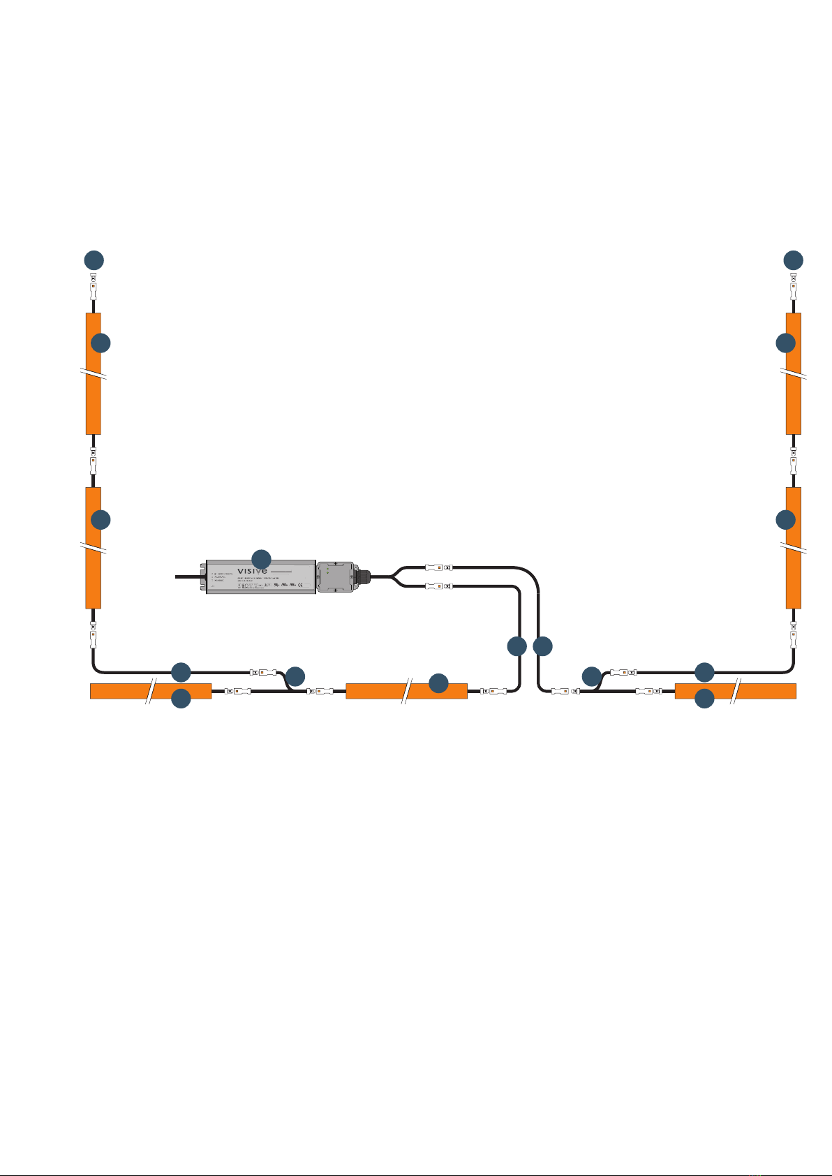
The installaon
Hi-Lite™ 30 installaons (see sample layout below) are made up from a number
of standard secons (1), connected end to end. A Field Adjustable Secon (2) is
usually fied at the end of each connuous run and is cut to size at the me of
installaon to exactly fit the structure.
Pre-terminated connecon cables (4) connect the Hi-Lite™ 30 secons to the
power supply (3), and are also used to bridge gaps around other signage or building
features. When the electrical connecon must connue aer an adjustable secon
(for example around a corner), a ‘Y’ connecon splier (5) is used together with a
connecon cable. Blanking plugs (6) must be fied to any unused connectors at
the end of tube runs.
Installaon key
1. Standard Hi-Lite™ 30 secons available
in 2.4m (7’10½”) lengths.
2. Field Adjustable Secons. Available in
2.4m (7’10½”) and 1.2m (3’11¼”) lengths.
3. 46V IP67 Power Supply Unit with CSC safety
system. Available in 240W, 96W, 40W and
20W versions.
Ordercode(s):
PS-S-240
PS-S-96
PS-S-40
PS-S-20
4. Pre-terminated connecon cables. Available
in 1m (3’3½”), 3m (9’11”), 5m (16’5”) and
10m (32’9¾”) lengths.
Ordercode(s):
JC2-S-1
JC2-S-3
JC2-S-5
JC2-S-10
5. ‘Y’ connecon splier.
Ordercode(s):YC2-S-FMM
6. Connector blanking terminator (supplied with
power supplies).
Ordercode(s):HL-BLANK

Page2 Hi-Lite™30LEDcontourtubespecicaon&installaon v6 – June 2021
The components
Hi-Lite™ 30 tubes are available in 2.4m (7’10½”) standard lengths and 2.4m
(7’10½”) and 1.2m (3’11¼”) Field Adjustable Secons. Most installaons are made
up from a number of standard secons, followed by a Field Adjustable Secon cut
to size during installaon.
Hi-Lite™ 30 standard secon (above) and
Field Adjustable Secon (right)
Standard secons feature a connector at each end and can be connected together
in a simple daisy-chain configuraon. Field Adjustable Secons have a connector
at one end only, and once cut to length the remaining poron is discarded.
The Hi-Lite™ 30 system also includes a range of IP-rated power supply units, as
well as connecon cables, ‘Y’ adapters, clips and connector blanking plugs.
Polycarbonate
mounng clip
‘Y’ splier adapters
Connector blanking
plugs (supplied with
power supplies)
SCIGRIP 16 acrylic
cement adhesive
for applying Field
Adjustable endcaps
Hi-Lite™ 30 adjustable
endcap
IP rated power supplies are available
in a range of power rangs
Patented ‘CSC’ safety system,
safeguards against electrical faults
Pre-terminated connecon
cables are available in a
range of lengths
VisiveGroupLimited
Ash Road South, Wrexham Industrial Estate, Wrexham, LL13 9UG +44 (0) 1978 660181
www.visivegroup.com
Page3 Hi-Lite™30LEDcontourtubespecicaon&installaon v6 – June 2021
<400mm
(1’3¾”)
<400mm
(1’3¾”)
<400mm
(1’3¾”)
<400mm
(1’3¾”)
<400mm
(1’3¾”)
<400mm
(1’3¾”)
50-70mm
(2”-2¾”)
50-70mm
(2”-2¾”)
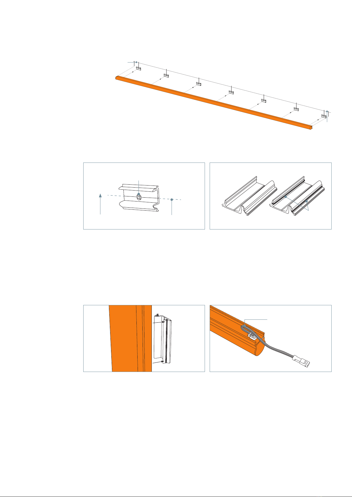
The installaon (connued)
1. Mounng clips must be installed
along a perfectly straight line. Clips installed
o-centre will pull the Hi-Lite™ 30 secon out of alignment.
Snap a chalk line on the mounng surface to use as a guide. Posion
a clip 50-70mm (2”-2¾”) from the end of each Hi-Lite™ 30 secon and at least every
400mm (1’3¾”) along each length.
2. On horizontal installs, clips must be
installed with the spring part of the clip to
the boom edge. The groove along the rear
of the clip indicates the centre line of the
Hi-Lite™ 30 tube once installed. Use fixings
with head diameter between 7mm (0.3”)
and 9mm (0.35”).
3. Two types of clip are supplied. A high-
fricon clip should be used in the centre of
the secon. This clip features a rubber ‘O’
ring to increase the grip on the tube, thereby
locking it in posion. Only one high-fricon
clip must be used per secon.
<400mm
(1’3¾”)
<400mm
(1’3¾”)
<400mm
(1’3¾”)
<400mm
(1’3¾”)
<400mm
(1’3¾”)
<400mm
(1’3¾”)
50-70mm
(2”-2¾”)
50-70mm
(2”-2¾”)
Thiswayup Chalkcentreline
Fixingscrew/rivet
Headdiameter:min7mm(0.3”),max9mm(0.35”)
Standardclip
4. On vercal installaons, the high-fricon
clip is parcularly important to prevent
Hi-Lite™ 30 secons from slipping down
over me.
5. If a standard secon is to connect to further
secons loop the output connecon as shown
before fing the tube into posion. Leave a
loop of cable to allow for movement due to
thermal expansion and contracon.
<400mm
(1’3¾”)
<400mm
(1’3¾”)
<400mm
(1’3¾”)
<400mm
(1’3¾”)
<400mm
(1’3¾”)
<400mm
(1’3¾”)
50-70mm
(2”-2¾”)
50-70mm
(2”-2¾”)
Loop of wire to
allowforthermal
movement
High-friconclip
‘O’ring
VisiveGroupLimited
Ash Road South, Wrexham Industrial Estate, Wrexham, LL13 9UG +44 (0) 1978 660181
www.visivegroup.com
Page4 Hi-Lite™30LEDcontourtubespecicaon&installaon v6 – June 2021
VisiveGroupLimited
Ash Road South, Wrexham Industrial Estate, Wrexham, LL13 9UG +44 (0) 1978 660181
www.visivegroup.com
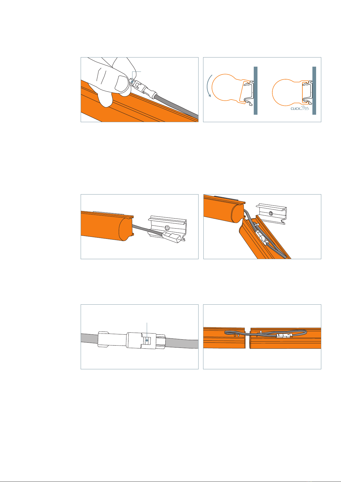
The installaon (connued)
6. If the secon is the end of the electrical
circuit, a connector blanking plug (supplied
with power supply) MUST be fied to the
unused connector. Failure to fit the blanking
plug may allow water to penetrate the
system, which will cause the CSC safety
device to remove power.
7. Hook the Hi-Lite™ 30 tube secon into the
top of the clip as shown, then rotate down
unl the boom edge clips into place. Ensure
the tube is properly located in the clip and
that no wires are trapped. A ‘click’ should be
heard when the tube is located correctly.
8. Hi-Lite™ 30 tube secon clipped in place,
with the cable posioned ready to connect
to the next secon.
9. Connect the next tube, looping the cable
around in the rear channel. Once again
leave a loop of cable to allow for thermal
movement.
10. In order to maintain weather sealing
connecons must be properly made. When
connected correctly the two halves will
be locked together and will not pull apart
without first releasing the locking tab.
Connectorblankingplug
11. Viewed from the rear of the tube, the
connecon is hidden within the rear channel.
When fixing the second secon, check
carefully that the cables are not trapped and
sit freely between the tube and the clips.
Lockingtab

Page5 Hi-Lite™30LEDcontourtubespecicaon&installaon v6 – June 2021
VisiveGroupLimited
Ash Road South, Wrexham Industrial Estate, Wrexham, LL13 9UG +44 (0) 1978 660181
www.visivegroup.com
The installaon (connued)
13. Hi-Lite™ 30 tube secons can be run
up to the edge of external corners. It is not
recommended to overlap the secons.
3M
3M
14. ‘Y’ splier adapters can be used with
Field Adjustable Secons to enable the
electrical circuit to connue (around corners
for example). The ‘Y’ adapter can be hidden
behind the tube in the same way as a
standard connecon.
15. If a connecon cable needs to be
shortened, this can be done using two 3M
Scotchlok gel-filled pigtail connectors, such
as type UY2. The completed connecon can
be hidden in the tube channel as shown.
3M
3M
3M
3M
Conneconcable
3MScotchlok
UY2pigtailconnectors
12. DO NOT bu secons up together.
Doing so will cause the secons to bend in
warm weather. Leave 10-15mm (0.4”-0.6”)
gap for thermal expansion. In very cold
weather a larger gap may be required.
If the Hi-Lite™ 30 secons are installed at a
2.4m (7’10½”) pitch, the required expansion
gaps will automacally be present.
10-15mm
(0.4”-0.6”)

Page6 Hi-Lite™30LEDcontourtubespecicaon&installaon v6 – June 2021
5. With the tube secon held
vercally, use strong tape to hold the
end-cap in posion. Wait for at least
15mins before handling the tube
further or moving it from the vercal
posion. The secon can be fied
aer 30mins.
PUSH
The installaon – Field Adjustable Secons
Only Field Adjustable Secons can be cut to size. Standard secons are NOT
adjustable. Do not aempt to cut a Hi-Lite™ 30 Field Adjustable Secon in wet
weather. No warranty is provided on water damaged Field Adjustable Secons.
1. Field Adjustable Hi-Lite™ 30 tubes can be
cut at specific locaons approximately every
50mm (2”). To locate a cut posion shine a
torch (or smart phone with torch funcon)
from the face side. Cut posions will be seen
as a row of three bright dots along the rear
of the tube. Mark the required cut posion.
2. Field Adjustable secons must be cut from
the connector end only. The poron cut o
without a connector is scrap and cannot be
used. Cut through the Hi-Lite™ 30 secon
at your mark using a hacksaw fied with a
fine-toothed blade. Use a mitre box to ensure
a clean, square cut.
3. Remove any burrs and foreign material
from the cut end. Ensure the cut is clean and
square (sand if necessary). The end-cap will
not form a weatherproof seal to an uneven
face. Before fing the field end-cap, push
the cut circuit board into the tube as far as
it will go.
PUSH
PUSH
4. Apply a generous, connuous bead of
SCIGRIP 16 to both the end-cap and the
cut end of the Hi-Lite™ 30 secon. Do not
substute any alternave adhesive or
sealant. Use SCIGRIP 16 in a well venlated
area, following the safety instrucons on
the tube.
PUSH
ApplySCIGRIP16asshown
VisiveGroupLimited
Ash Road South, Wrexham Industrial Estate, Wrexham, LL13 9UG +44 (0) 1978 660181
www.visivegroup.com

Page7 Hi-Lite™30LEDcontourtubespecicaon&installaon v6 – June 2021
The installaon – Current Sense Circuit (CSC) operaon
The Current Sense Circuit (CSC) is an integral part of the PSU. Its funcon is to
connuously monitor the installaon and remove the low-voltage supply should
a fault be detected. Whilst it is primarily a safety feature, it can also assist in
troubleshoong.
The CSC has a status LED which indicates the current state of the circuit. On
the standard 240W supply there is an LED for each output channel. The CSC is a
sophiscated electronic device which takes a number of complex measurements
from the system in order to recognise fault condions.
It is not necessary to understand the detailed funcons of the operaon algorithms
in order to successfully install or troubleshoot a Hi-Lite™ installaon, however a
descripon of the CSC and its operaon is set out below for informaon.
Operaon
During normal operaon the CSC connuously and automacally performs tests
on the DC supply to the Hi-Lite™ installaon. Should a fault be detected the DC
output is switched o. Once this has occurred, a series of aempts to reinstate the
DC supply are made at intervals increasing from 1 second to 1 hour.
Should any re-try be successful, the DC output is switched on and the CSC enters
a back-o mode. Whilst in this back-o mode the re-try period that will be applied,
should a further fault be detected, is slowly reduced back to 1 second.
Should the fault sll be present aer the full retry cycle (around 5 hours), the CSC
enters an abort mode. Once in this mode, no further retries are made and the
status LED flashes red.
When a fault is detected, the status LED pulses a number of mes rates to indicate
the type of fault. The table below lists these faults.
Pulse rao Fault indicated
2 pulses Start-up impedance test failure
3 pulses Current monitor failure
4 pulses Run-me impedance test failure
5 pulses Reserved
6 pulses Run-me voltage test failure
7 pulses Start-up voltage test failure
8 pulses Over-current
VisiveGroupLimited
Ash Road South, Wrexham Industrial Estate, Wrexham, LL13 9UG +44 (0) 1978 660181
www.visivegroup.com

Page8 Hi-Lite™30LEDcontourtubespecicaon&installaon v6 – June 2021
Possible causes for each fault type are:
2 pulses: Start-up impedance test failure
The system has detected a low resistance across the output before it has applied
power. This can be caused by a faulty or damaged tube secon, badly made
connecons between secons or water inside the connectors.
3 pulses: Current monitoring failure
The system has detected fluctuaons in current in the installaon. This is usually
caused by a faulty or damaged tube secon or a badly made connecon between
secons.
4 pulses: Run-me impedance test failure
Similar to 2 pulses, but this test is carried out at 10 second intervals during normal
operaon.
6 pulses: Run-me voltage test failure
This test is carried out at 10 second intervals during normal operaon and a failure
indicates either a faulty or damaged tube secon (usually with water ingress, or
the connectors contain trapped water).
7 pulses: Start-up voltage test failure
Similar to 6 pulses, but this test is carried out at start-up, before power is applied.
8 pulses: Over-current failure
The load exceeds the maximum allowed. Reduce the load on the output channel.
Should the mains input to the PSU be cycled once the CSC is in the abort mode, the
CSC first aempts a power-up. If this is successful, normal operaon resumes and
the CSC enters its connuous monitoring mode once again.
VisiveGroupLimited
Ash Road South, Wrexham Industrial Estate, Wrexham, LL13 9UG +44 (0) 1978 660181
www.visivegroup.com
Page9 Hi-Lite™30LEDcontourtubespecicaon&installaon v6 – June 2021
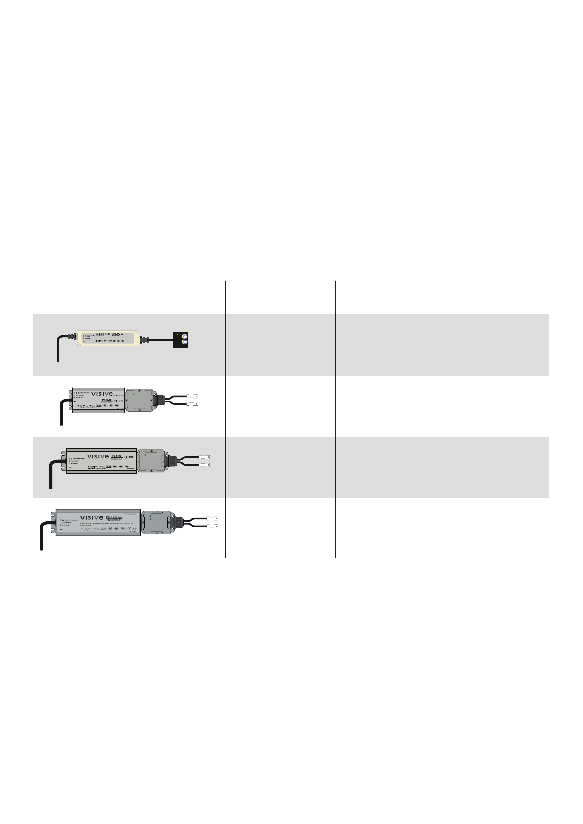
The installaon – PSU loadings
All IP-rated power supply units feature twin outputs. On 20W, 40W and 96W
supplies, these outputs are internally connected in parallel so Hi-Lite™ 30 secons
can be connected in any combinaon.
For example, all the secons can be connected to only one output, or they can be
split in any combinaon across the outputs.
240W power supplies feature two independent outputs, each capable of delivering
up to 120W. If any power supply outputs are not used, be sure to fit a blanking plug
to the unused connector.
Power supply Total output power Hi-Lite™ 30 green
(HL3-xx-G5)
All other colour
codes
18m (59’1”) total in
any configuraon
across the two
outputs
36m (118’3”) total
in any configuraon
across the two
outputs
43m (141’1”) max
on each output, 86m
(282’2”) total
N/A
4m (13’1½”) total in
any configuraon
across the two
outputs
19m (62’4”) total in
any configuraon
across the two
outputs
24m (78’9”) max. on
each output, 48m
(157’5¾”) total
20W
40W
96W
2 x 240W
VisiveGroupLimited
Ash Road South, Wrexham Industrial Estate, Wrexham, LL13 9UG +44 (0) 1978 660181
www.visivegroup.com
PS-S-240
PS-S-96
PS-S-40
PS-S-20
8m (26’3”) total in
any configuraon
across the two
outputs

www.visivegroup.com
UKOce
VisiveGroupLtd
AshRoadSouth,
WrexhamIndustrialEstate,
Wrexham,UK
LL139UG
T:+44(0)1978660181
Email:info@visivegroup.com
ChinaOce
VisiveGroup(Guangzhou)
CommercialLighngCo.Ltd.
Rm.1707,TianyinBldg.,
437ZhongshanAvenue,
TianheGuangzhou,
China,510660
T:+862023836842
Contact:AndyZheng–Director
Email:za@auxisoluon.com
IrelandDistributor
TrimwelLtd
2ACanalBank,
HumeAvenue,
ParkWestIndustrialEstate,
Dublin12,Ireland
T:00353(0)12940188
Email:inf[email protected]
Distributor
BeverInnovaonsB.V.
Industrieweg32,
4301RSZierikzee,
TheNetherlands
T:+31(0)111453232
Email:info@beverinnovaons.com
Distributor
dkLED
Ekkersrijt1209,
5692AGSonenBreugel,
TheNetherlands
T:+31499476777
Email:inf[email protected]
USAStockist
Wired4SignsUSA,LLC.
7669ClintonHighway
Powell,TN37849,USA
T:+1(865)3394956
www.wired4signsusa.com
This manual suits for next models
3
Table of contents


