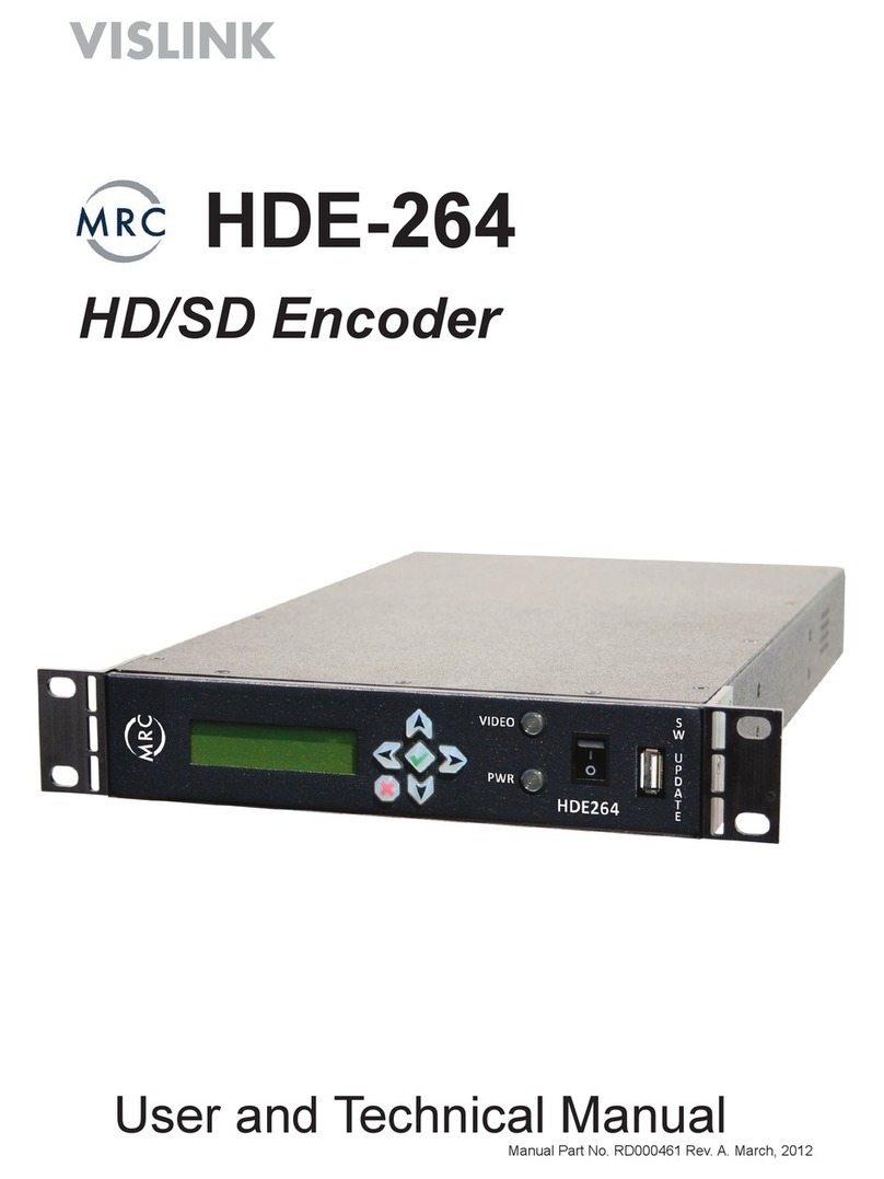
Vislink UltraDecoder User manual

VISLINK. Vislink House, 27 Maylands Avenue, Hemel Hempstead, Hertfordshire, HP2 7DE, United Kingdom.
Telephone: +44 (0)1442 431300 ●Facsimile: +44 (0)1442 431301 ●Email: s[email protected] ●Website: www.vislink.com
Company Registered in England no. 1910243 VAT registration no. 448 636 222
Registered Office: Marlborough House, Charnham Lane, Hungerford, Berkshire, RG17 0EY

Issue: 4 Page : ii
Ref: ULTD-ASUM-7001 Copyright © 2016 Vislink plc
The information contained in this manual remains the property of Vislink and may not be
used, disclosed or reproduced in any other form whatsoever without the prior written
permission of Vislink.
Vislink reserves the right to alter the equipment and specification appertaining to the
equipment described in this manual without notification.
This document is supplied on the express terms that it is to be treated as confidential and
that it may not be copied, used or disclosed to others for any purpose except as authorized
by Vislink.
NOTE: Notes are used to convey additional information.
Caution: Cautionary notes are given where potential equipment damage could occur.
Warning: Warnings are shown where there is potential for personal danger or death. This
warning should be read and understood before attempting to carry out any work
on any equipment attached or related to the equipment in use. The danger is real
and ignoring or not understanding the warning could lead to injury, harm or
potential death.

Issue: 4 Page : iii
Ref: ULTD-ASUM-7001 Copyright © 2016 Vislink plc
Version
Date
Modification
Firmware Version
1
26/11/2015
Initial release
2
14/12/2015
Added IP Setup and Decoder
communications recovery procedure
3
21/12/2015
Added Read Me First, Quick Start Guide
and full Menu Tree. Upgrade procedure
modified. Miscellaneous corrections.
AUTOBOOT P00016 Vt00
4
17/3/2016
General revision for new release.
Updated template to new look
manual.
Versions contained in 2016-03-
16_Ultradecoder
Controller software:
AUTOBOOT_P0016_V1009
HEVC decoder software:
9261update-2016-01-20_16-29-20

Issue: 4 Page : iv
Ref: ULTD-ASUM-7001 Copyright © 2016 Vislink plc
1. Introduction .............................................................................................................. 1
2. Read Me First ............................................................................................................ 3
3. Quick Start Guide....................................................................................................... 5
3.1. Connectivity Configuration.....................................................................................................5
3.2. Input Configuration ................................................................................................................6
3.3. Output Configuration .............................................................................................................8
4. Specifications ............................................................................................................ 9
4.1. Physical ...................................................................................................................................9
4.2. Inputs......................................................................................................................................9
4.3. Outputs...................................................................................................................................9
4.4. Remote Control/Monitoring...................................................................................................9
4.5. Performance .........................................................................................................................10
4.5.1. H.265 Video Formats, Resolution & Bitrates ................................................................10
4.5.2. Audio.............................................................................................................................10
4.5.3. IP Video .........................................................................................................................10
5. Front Panel.............................................................................................................. 11
5.1. Buttons .................................................................................................................................11
5.1.1. MENU............................................................................................................................11
5.1.2. ESCAPE ..........................................................................................................................11
5.1.3. STATUS ..........................................................................................................................11
5.1.3.1. ALARM LED............................................................................................................11
5.1.3.2. POWER LED ...........................................................................................................11
5.1.4. Navigation (˄˅˂˃)......................................................................................................11
5.1.5. ENTER............................................................................................................................11
5.2. Menu Screen.........................................................................................................................12
5.3. USB........................................................................................................................................12
6. Rear Panel ............................................................................................................... 13
6.1. IP VIDEO................................................................................................................................13
6.1.1. IP to ASI .........................................................................................................................13
6.2. ETHERNET CONTROL.............................................................................................................13
6.3. ASI IN.....................................................................................................................................13
6.4. DATA .....................................................................................................................................13
6.4.1. MPEG DATA...................................................................................................................13
6.4.2. Status Relay...................................................................................................................13
6.4.3. Pin Outs.........................................................................................................................14
6.5. USB........................................................................................................................................14
6.6. ETH. 1....................................................................................................................................14
6.7. ETH. 2....................................................................................................................................14
6.8. ASI OUT.................................................................................................................................14
6.9. 3G SDI ...................................................................................................................................14
6.10. 4K HDMI................................................................................................................................15
6.11. AC Power ..............................................................................................................................15
7. IP Setup................................................................................................................... 17
7.1. Basic......................................................................................................................................17

Issue: 4 Page : v
Ref: ULTD-ASUM-7001 Copyright © 2016 Vislink plc
7.2. Web Browser Control ...........................................................................................................18
7.3. IP VIDEO In............................................................................................................................18
7.4. Complete Configuration .......................................................................................................19
8. Menu Navigation..................................................................................................... 21
8.1. Decoder Setup ......................................................................................................................21
8.1.1. Video .............................................................................................................................21
8.1.1.1. Program Number ..................................................................................................21
8.1.1.2. Format...................................................................................................................21
8.1.1.3. Restart Decoder ....................................................................................................21
8.1.2. Audio.............................................................................................................................22
8.1.2.1. Audio 1..4 PID........................................................................................................22
8.2. Unit Setup.............................................................................................................................22
8.2.1. IP Options......................................................................................................................22
8.2.1.1. IP Video In .............................................................................................................22
8.2.1.1.1. Port.....................................................................................................................22
8.2.1.1.2. Status .................................................................................................................22
8.2.1.2. IP Port Setup..........................................................................................................22
8.2.1.2.1. Addr....................................................................................................................22
8.2.1.2.2. Mask...................................................................................................................22
8.2.1.2.3. Gway ..................................................................................................................22
8.2.1.2.4. Traffic .................................................................................................................22
8.2.2. ASI Options....................................................................................................................23
8.2.2.1. ASI Out ..................................................................................................................23
8.2.2.2. ASI Out Mode........................................................................................................23
8.2.3. Decoder Input ...............................................................................................................23
8.2.3.1. Decoder Input .......................................................................................................23
8.3. System ..................................................................................................................................24
8.3.2. Presets...........................................................................................................................25
8.3.2.1. Recall from Memory .............................................................................................25
8.3.2.1.1. Preset .................................................................................................................25
8.3.2.1.2. Name..................................................................................................................25
8.3.2.1.3. Recall..................................................................................................................25
8.3.2.2. Store to Memory...................................................................................................25
8.3.2.2.1. Preset .................................................................................................................25
8.3.2.2.2. Name..................................................................................................................25
8.3.2.2.3. Store...................................................................................................................25
8.3.2.3. USB Transfer..........................................................................................................25
8.3.2.3.1. Recall..................................................................................................................26
8.3.2.3.2. Store...................................................................................................................26
8.3.2.4. Restore Defaults....................................................................................................26
8.3.2.4.1. Restore Defaults.................................................................................................26
8.3.2.4.2. IP Defaults..........................................................................................................26
8.3.3. Remote Interfaces.........................................................................................................26

Issue: 4 Page : vi
Ref: ULTD-ASUM-7001 Copyright © 2016 Vislink plc
8.3.3.1. Ethernet ................................................................................................................26
8.3.3.1.2. IP ........................................................................................................................27
8.3.3.1.3. Mask...................................................................................................................27
8.3.3.1.4. Gway ..................................................................................................................27
8.3.3.1.5. MAC....................................................................................................................27
8.3.3.2. Web Identifier .......................................................................................................27
8.3.3.2.1. ID........................................................................................................................27
8.3.4. Service...........................................................................................................................27
8.3.4.1. Licences.................................................................................................................27
8.3.4.1.1. ESN.....................................................................................................................27
8.3.4.1.2. Line 1..................................................................................................................27
8.3.4.1.3. Line 2..................................................................................................................27
8.3.4.1.4. State...................................................................................................................27
8.3.4.2. Time.......................................................................................................................28
8.3.4.2.1. Time ...................................................................................................................28
8.3.4.2.2. Date....................................................................................................................28
8.3.4.2.3. Format................................................................................................................28
8.3.4.2.4. Run Hours...........................................................................................................28
8.3.4.3. Miscellaneous .......................................................................................................28
8.3.4.3.1. Lamp Test...........................................................................................................28
8.3.4.3.2. Contrast..............................................................................................................28
8.3.4.3.3. Fault Test............................................................................................................28
8.3.4.3.4. Reboot................................................................................................................28
8.3.5. Help...............................................................................................................................28
8.3.5.1. Unit Version...........................................................................................................28
8.3.5.2. Decoder Version....................................................................................................28
8.3.5.3. Support..................................................................................................................29
9. Remote Control ....................................................................................................... 31
9.1. SNMP ....................................................................................................................................31
9.3. Web Browser ........................................................................................................................32
9.3.1. Overview .......................................................................................................................32
9.3.2. Alarm Logging................................................................................................................34
Appendix A Software Upgrades ................................................................................. 35
A.1. Locating the Upgrade Files and Pre-Update Information.....................................................35
A.2. Upgrading Unit Controller via the Front Panel USB Port......................................................36
A.3. Upgrading Decoder via the Rear Panel USB .........................................................................36
Appendix B Decoder Communications Recovery Procedure ....................................... 37
Appendix C Maintenance & Fault Finding .................................................................. 39
Appendix D Declarations of Conformity ..................................................................... 41
D.1. EC Declaration of Conformity ...............................................................................................41
D.2. Federal Communications Commission Statement ...............................................................42
Appendix E Full Menu Tree ....................................................................................... 43

Issue: 4 Page : vii
Ref: ULTD-ASUM-7001 Copyright © 2016 Vislink plc
Figure 1-1 Ultra Decoder Overview................................................................................................ 1
Figure 3-1 Routing Tab ................................................................................................................... 6
Figure 3-2 IP Video Tab................................................................................................................... 7
Figure 3-3 Decoder Tab .................................................................................................................. 8
Figure 5-1 Front Panel Overview.................................................................................................. 11
Figure 6-1 Rear Panel Overview ................................................................................................... 13
Figure 7-1 Basic Control Ethernet Connection Configuration...................................................... 17
Figure 7-2 Web Browser Control Ethernet Connection Configuration ........................................ 18
Figure 7-3 IP VIDEO IN Connection Configuration ....................................................................... 18
Figure 7-4 Complete Configuration Connection Configuration ................................................... 19
Figure 9-1 Web Browser Overview............................................................................................... 32
Figure 9-2 Routing Tab Overview ................................................................................................. 33
Figure 9-3 Alarm Logging Tab Overview....................................................................................... 34
Figure A-1 Basic Configuration ..................................................................................................... 35
Figure B-1 Web Interface Screen.................................................................................................. 38
Table 6-1 Data Out Pinouts ......................................................................................................... 14
Table 8-1 Decoder Setup Menu Overview.................................................................................. 21
Table 8-2 Unit Setup Menu Overview......................................................................................... 22
Table 8-3 System Setup Menu Overview .................................................................................... 24
Table 9-1 Web Browser Overview Functions.............................................................................. 32
Table C-1 Maintenance Error Table ............................................................................................ 39

Issue: 4 Page : viii
Ref: ULTD-ASUM-7001 Copyright © 2016 Vislink plc
This page is intentionally unused.

UltraDecoder Operators Manual
Introduction
Issue: 4 1
Ref: ULTD-ASUM-7001 Copyright © 2016 Vislink plc
Figure 1-1 Ultra Decoder Overview
The Vislink UltraDecoder is the lightest new 1RU, half-rack width HEVC & 4K UHD capable
decoder in the world.
The system uses the latest advanced HEVC decoding techniques to offer up to 50% bit-rate
reduction compared to H.264.
In conjunction with Vislink's UltraCoder, the UltraDecoder provides a complete end to end
HEVC and 4K UHD encode and decode solution.
Full remote control is made possible using either SNMP or by the internal web server from
your preferred web browser. A clear graphical routing page in the web-browser interface
gives total control of all the possible combinations. This common control interface contains
links to the adjustable parameters for the unit.
This manual provides information on the complete range available.
NOTE: Not all options are fitted at time of manufacture. Some hardware upgrades may
require you to return the unit(s) to the factory.
NOTE: Additional licence keys, purchased to enable functions not initially ordered, may be
entered in the field.
Firmware upgrades may be offered from time to time for the customer to download into
the unit to add additional features as they become available.

UltraDecoder Operators Manual
Introduction
Issue: 4 2
Ref: ULTD-ASUM-7001 Copyright © 2016 Vislink plc
This page is intentionally unused.

UltraDecoder Operators Manual
Read Me First
Issue: 4 3
Ref: ULTD-ASUM-7001 Copyright © 2016 Vislink plc
The UltraDecoder is composed of two subsystems integrated within the chassis; a control
assembly and a decoder assembly. These subsystems communicate by Ethernet using the
four RJ45 connectors on the rear panel. Before the unit is powered on it is vital that these
connectors are configured in such a way that the subsystems can communicate.
To achieve a working link using the supplied cables, do either of the following:
1. Directly connect Eth. 1 to IP Video and Eth. 2 to Ethernet Control or;
2. Connect all four ports to an external Ethernet switch.
NOTE: This is shown in more detail in Chapter 7.
We recommend you use option 1. above for the initial port addresses configuration.
If the unit is to be connected to an external network, with more than one UltraDecoder
unit present, then the default IP addresses of the ports must be changed before connecting
to the external network in order to prevent IP Address clashes.
CAUTION: If an UltraDecoder is powered on without the correct network connections in
place, then the control and decoder subsystems may lose communication. If
communications are lost, follow the recovery procedure in Appendix B.

UltraDecoder Operators Manual
Read Me First
Issue: 4 4
Ref: ULTD-ASUM-7001 Copyright © 2016 Vislink plc
This page is intentionally unused.

UltraDecoder Operators Manual
Quick Start Guide
Issue: 4 5
Ref: ULTD-ASUM-7001 Copyright © 2016 Vislink plc
In the first instance, we recommend configuring the unit using the front panel interface
controls.
The procedure for configuring the web interface is as follows:
1. First, make the direct Ethernet connections on the rear panel using the supplied
cables, as described in Section 2.
2. If required, configure the Ethernet Control port with the appropriate IP Address,
Mask and Gateway to match your network settings. The settings for this can be
found from the front panel by selecting:
Menu | System | Remote Interfaces | Ethernet Port.
3. If you are connecting the IP Video port and Eth. 1 to your network, configure the IP
Video port by selecting:
Menu | Unit Setup | IP Options | IP Port Setup
NOTE: If you are using a direct connection, the default values can be left as is.
NOTE: If a direct connection is used between the IP Video and Eth. 1 ports then the unit
can only be used in ASI input mode.
4. Power the unit off and safely remove the supplied cables.
CAUTION: Make sure you connect the Ethernet ports to your network before reapplying
power to avoid the control and decoder subsystems loosing communication.
Access the Web Interface using the same IP address as the Ethernet Control port.

UltraDecoder Operators Manual
Quick Start Guide
Issue: 4 6
Ref: ULTD-ASUM-7001 Copyright © 2016 Vislink plc
Use the switches on the routing page shown in Figure 3-1 to select the correct source
signal for the decoder. Select either the ASI input or the IP input. Press Accept Changes to
save the changes.
NOTE: Only one change can be made at a time.
If the ASI IN input is selected, then no further input configuration is required.
Figure 3-1 Routing Tab

UltraDecoder Operators Manual
Quick Start Guide
Issue: 4 7
Ref: ULTD-ASUM-7001 Copyright © 2016 Vislink plc
If the IP IN input is selected, it is necessary to select a receiving port number from the tab
as shown in Figure 3-2:
IP|IP Video In
The receiving address will be as configured for the IP Video port in Section 3.1. The unit
used to transmit the IP Video must be configured with matching settings.
A tick will appear in the status box top in the page header Once the system detects
incoming ASI or IP packets.
Figure 3-2 IP Video Tab

UltraDecoder Operators Manual
Quick Start Guide
Issue: 4 8
Ref: ULTD-ASUM-7001 Copyright © 2016 Vislink plc
Refer to Figure 3-3 for the following output configuration:
1. If the incoming ASI stream contains more than one program, select the program
number the Select Program Number from the dropdown list in the Decoder tab.
2. Select the output format from the Video format field. The decoder will automatically
recognize the format of the incoming ASI stream and will up-scale or down-scale to
the selected format.
NOTE: It is important to select the same frame rate as the incoming ASI stream as the
decoder cannot change this.
3. Change the Play control to PLAY.
If a monitor is connected to the HDMI ports (All formats) or SDI ports (HD and SD only)
video should now display.
Figure 3-3 Decoder Tab

UltraDecoder Operators Manual
Specifications
Issue: 4 9
Ref: ULTD-ASUM-7001 Copyright © 2016 Vislink plc
Feature
Description
Dimensions
1RU half-width chassis x 350mm deep
Weight
1.9kg approx. (4lbs)
Power Connector
3 pin IEC plug with dual fusing
AC Supply
90-264V AC 50/60Hz @ <100VA
Temperature Range
0 to +50°C operating, -20°C to +70°C storage
Humidity
90% max. non-condensing
Data
15way D-Type female
Ethernet Control & IP Video
RJ45
USB Ports
Type A
2x 3G SDI
HD BNC
ASI connections
BNC 75Ω
HDMI
1.4b (4.2.0 - 10 bit) Type A
Feature
Description
IP Video
10/100/1000 Base-T Ethernet
ASI
75Ω to ISO/IEC 13818-2 188/204Bytes constant rate
Feature
Description
ASI
75Ω to ISO/IEC 13818-2 188/204Bytes constant rate
HDMI
4K (4096 x 2160) or Ultra-HD (3840 x 2160), HD or SD (1.4b)
3G SDI
SMPTE 424M
Feature
Description
USB
For software upgrades
Remote Control
10/100Mb/s Web Browser/SNMP
IP Address (factory default)
192.168.2.6
Subnet Mask (factory default)
255.255.255.0
MAC Address
00.1D.65.nn.nn.nn (n will be unit specific)

UltraDecoder Operators Manual
Specifications
Issue: 4 10
Ref: ULTD-ASUM-7001 Copyright © 2016 Vislink plc
Feature
Description
4K UHD Main 10
8/10 bit 4.2.0 1.0 –40.0Mb/s
HD Main 10
8/10 bit 4.2.0 1.0 –40.0Mb/s
SD Main
4.2.0 0.5 –6.0Mb/s
Formats
480i @ 29.97
576i @ 25
720p @ 50, 59.94 & 60
1080i @ 50, 59.94 & 60
1080p @ 23.98, 24, 25, 29.97, 30, 50, 59.94 & 60
UHD @ 23.98, 24, 25, 29.97, 30, 50, 59.94 & 60
4K @ 23.98, 24, 25, 29.97, 30, 50, 59.94 & 60
Feature
Description
Decoder
ISO 14496-3 2006 (HE-AAC) 4 pairs
Outputs
Embedded
Feature
Description
Type
10/100/1000 Base-T Ethernet
Protocol
IEEE802.3 Ethernet
Encapsulation for ASI –RTP (RFC2250), ARP, IPv4, IGMPv2/3,
TCP/UDP

UltraDecoder Operators Manual
Front Panel
Issue: 4 11
Ref: ULTD-ASUM-7001 Copyright © 2016 Vislink plc
Figure 5-1 Front Panel Overview
Selecting the MENU button toggles between the menus and the AV lock status screen. It
also returns the menu screen to the main operating level from any point (as long as an
item is not being edited).
As long as an item is not being edited, selecting the ESCAPE button returns the menu
screen to the level above the current screen on display.
If an item is currently being edited, selecting the ESCAPE button cancels the change being
made and returns the item to the previously stored value.
Selecting the STATUS button toggles from the MENU screen to display the Alarm screen.
Pressing the button again returns the display to the previously displayed screen.
The Alarm LED is a tricolour LED and illuminates in different colours depending on the
alarm status:
Green shows when the system is operating as expected i.e. no alarms.
Amber shows if the system generates a warning, indicating that there is an issue you
need to be aware of.
Red shows if the system is in an error state.
Details of the errors and warnings are displayed in the Alarms screen. You can configure
which items to display as alarms and configure set their severity levels using the internal
web interface.
This LED will be illuminated green when power is applied to the unit.
˄ ˅ ˂ ˃
These buttons are used to navigate up, down, left and right around the menu screens.
This button will apply and store the selected value when editing an item.

UltraDecoder Operators Manual
Front Panel
Issue: 4 12
Ref: ULTD-ASUM-7001 Copyright © 2016 Vislink plc
The menu screen provides the facility to configure all aspects of the unit via the front panel
buttons. See Section 8 for full details of the menu structures and functions.
This connector provides the facility to upgrade the unit’s software via a USB memory stick,
as well as downloading and uploading the unit configuration.
See Appendix A for details on upgrading the unit.
Other manuals for UltraDecoder
2
This manual suits for next models
1
Table of contents
Other Vislink Media Converter manuals
