Vislink UltraCoder User manual

VISLINK. Vislink House, 27 Maylands Avenue, Hemel Hempstead, Hertfordshire, HP2 7DE, United Kingdom.
Telephone: +44 (0)1442 431300 ● Facsimile: +44 (0)1442 431301 ● Email: s[email protected] ● Website: www.vislink.com
Company Registered in England no. 1910243 VAT registration no. 448 636 222
Registered Office: Marlborough House, Charnham Lane, Hungerford, Berkshire, RG17 0EY
UltraCoder
OPERATORS MANUAL

UltraCoder Operators Manual
Contents
Issue : 3 (16/12/2015) i
Ref : ULTC-ASUM-7001 Copyright © Vislink plc
Contents
1. Introduction........................................................................................................................................ 1
2. Specifications ...................................................................................................................................... 3
2.1. Physical .......................................................................................................................................................3
2.2. Inputs .......................................................................................................................................................... 3
2.3. Outputs ...................................................................................................................................................... 3
2.4. Remote Control/Monitoring.................................................................................................................3
2.5. Performance.............................................................................................................................................. 3
3. Front Panel.......................................................................................................................................... 5
3.1. Buttons ....................................................................................................................................................... 5
3.2. Menu Screen..............................................................................................................................................6
3.3. USB.............................................................................................................................................................. 6
4. Rear Panel ........................................................................................................................................... 7
4.1. IP Video ......................................................................................................................................................7
4.2. Ethernet Control .....................................................................................................................................8
4.3. ASI In........................................................................................................................................................... 8
4.4. Data............................................................................................................................................................. 8
4.5. SFP 1 & 2....................................................................................................................................................9
4.6. ASI Out....................................................................................................................................................... 9
4.7. SD Card...................................................................................................................................................... 9
4.8. AC Power..................................................................................................................................................9
5. Menu Navigation..............................................................................................................................11
5.1. Encoder Setup.........................................................................................................................................11
5.2. Audio Setup.............................................................................................................................................14
5.3. Unit Setup................................................................................................................................................16
5.4. System.......................................................................................................................................................22
6. Remote Control .............................................................................................................................. 27
6.1. SNMP ........................................................................................................................................................27
6.2. Web Browser .........................................................................................................................................28
7. Appendices........................................................................................................................................ 31
7.1. Appendix A –Software Upgrades .....................................................................................................31
7.2. Appendix B –Maintenance & Fault Finding .....................................................................................32
7.3. Appendix C –BISS Video Encryption ...............................................................................................33
7.4. Appendix D –Electrical Safety ...........................................................................................................34

UltraCoder Operators Manual
Document Disclaimer
Issue : 3 (16/12/2015) ii
Ref : ULTC-ASUM-7001 Copyright © Vislink plc
Document Disclaimer
The information contained in this manual remains the property of Vislink and may not be used,
disclosed or reproduced in any other form whatsoever without the prior written permission of
Vislink.
Vislink reserves the right to alter the equipment and specification appertaining to the equipment
described in this manual without notification.

UltraCoder Operators Manual
Document History
Issue : 3 (16/12/2015) iii
Ref : ULTC-ASUM-7001 Copyright © Vislink plc
Document History
Version
Date
Modification
1
11/11/2015
Initial release
2
24/11/2015
Changes to menu structure
3
16/12/2015
Modified ASI to IP description. Updated ASI Out options. Removed
Dolby references –not currently supported. Modified Introduction
text
UltraCoder Operators Manual
Introduction
Issue : 3 (16/12/2015) Page : 1
Ref : ULTC-ASUM-7001 Copyright © Vislink plc
1. Introduction
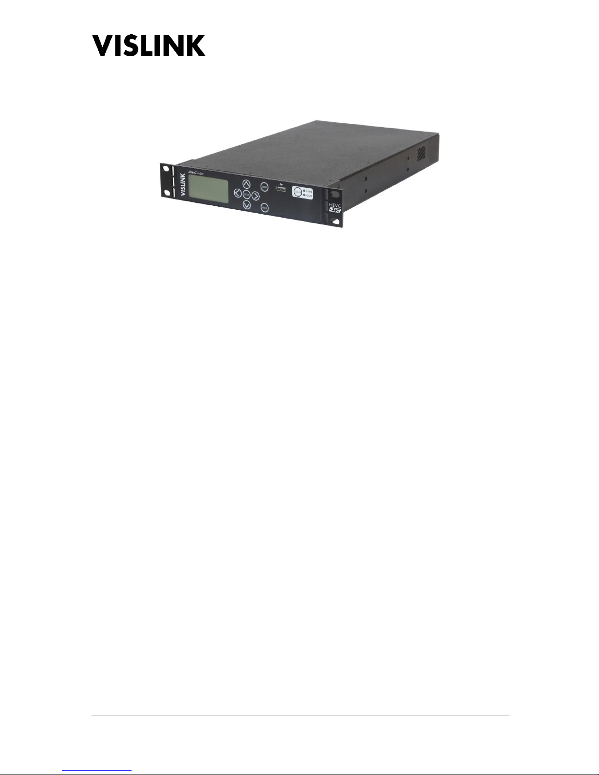
The Vislink UltraCoder is a lightweight 1RU, half-rack width HEVC encoder capable of encoding 4K
UHD, HD and SD video.
The system uses the latest advanced HEVC encoding techniques to offer up to 50% bit rate reduction
compared to H.264, resulting in the delivery of high quality video at low bit rates. It has the ability to
encode one 4K UHD video or up to four simultaneous HD video streams, making it the most
advanced encoder in its range. Being so lightweight, it’s ideal for flyaway or vehicle mounted
applications, where weight and space is critical.
Along with Vislink’s UltraDecoder this product provides a complete end to end HEVC & 4K encode
and decode solution.
The unit includes two user configurable SFP+ video interface module slots.
An Ethernet connector provides IP Video connectivity, with the flexibility to operate the
encapsulation/de-encapsulation process with internal encoding or, independently from the encoding
process.
The IP video streaming output can be sourced from the inbuilt video encoder or from an external ASI
source; the output will be packetized ASI in an Ethernet format. The IP input (same connector as the
output that can be used at the same time) can receive IP encapsulated ASI and convert back to ASI.
This ASI can either be an additional source to the ‘local’ encoder, forming a multiplex with it, or to
provide an independent ASI output.
IP Data can be carried over ASI, multiplexed with the local video encoder to provide a one direction
data path.
Full remote control can be made either by SNMP or by accessing the internal web server from a web
browser. A clear graphical routing page in the web-browser interface gives total control of all the
possible combinations. This common control page also contains automatic links to all adjustable
parameters of the unit at a single click.
This manual provides information on the complete range available; note that not all options are
fitted at time of manufacture, and may require a return to factory for future hardware upgrades.

UltraCoder Operators Manual
Introduction
Issue : 3 (16/12/2015) Page : 2
Ref : ULTC-ASUM-7001 Copyright © Vislink plc
Purchases of additional licence keys to enable functions not initially ordered may be entered in the
field.
Firmware upgrades may be offered from time to time for the customer to download into the unit to
add additional features as they become available.
Please note that when the unit is configured to encode four simultaneous HD video streams,
interruption of any input will not affect the other channels, however the interrupted channel will not
recover automatically. The channel must be manually reset, which will affect all four channels,
therefore should only be performed when operationally convenient to do so.

UltraCoder Operators Manual
Specifications
Issue : 3 (16/12/2015) Page : 3
Ref : ULTC-ASUM-7001 Copyright © Vislink plc
2. Specifications
2.1. Physical
Feature
Description
Dimensions
1RU half-width chassis x 350mm deep
Weight
1.9kg approx. (4lbs)
Power Connector
3 pin IEC plug with dual fusing
AC Supply
90-264V AC 50/60Hz @ <100VA
Temperature Range
0 to +50°C operating, -20°C to +70°C storage
Humidity
90% max. non-condensing
Data
15way D-Type female
Ethernet Control & IP Video
RJ45
USB Ports
Type A
SFP
HD BNC 75Ω
ASI connections
BNC 75Ω
2.2. Inputs
Feature
Description
4 x HD-SDI
Standard interface SFP modules supplied. Optical/HDMI on request.
ASI
75Ωto ISO/IEC 13818-2 188Bytes constant rate
2.3. Outputs
Feature
Description
ASI
75Ω to ISO/IEC 13818-2 188Bytes constant rate
IP Video
10/100/1000 Base-T Ethernet
2.4. Remote Control/Monitoring
Feature
Description
USB
For software upgrades
Remote Control
10/100Mb/s Web Browser/SNMP
IP Address (factory default)
192.168.0.90
Subnet Mask (factory default)
255.255.255.0
MAC Address
00.1D.65.nn.nn.nn (n will be unit specific)
2.5. Performance
2.5.1. H.265 VIDEO FORMATS,RESOLUTION &BITRATES
Feature
Description
4K UHD Main 10
8/10 bit 4.2.0 1.0 –25.0Mb/s
4K UHD Main 4.2.2 10
8/10 bit 4.2.0/4.2.2 1.0 –25.0Mb/s
HD Main 10
8/10 bit 4.2.0 1.0 –20.0Mb/s
HD Main 4.2.2 10
8/10 bit 4.2.0/4.2.2 1.0 –20.0Mb/s
SD Main
4.2.0 0.5 –6.0Mb/s
SD Main 4.2.2
4.2.2 2.0 –6.0Mb/s

UltraCoder Operators Manual
Specifications
Issue : 3 (16/12/2015) Page : 4
Ref : ULTC-ASUM-7001 Copyright © Vislink plc
Feature
Description
Formats
480i @ 29.97
576i @ 25
720p @ 50, 59.94 & 60
1080i @ 50, 59.94 & 60
1080p @ 23.98, 24, 25, 29.97, 30, 50, 59.94 & 60
2160p @ 23.98, 24, 25, 29.97, 30, 50, 59.94 & 60
2.5.2. AUDIO
Feature
Description
Encoder
ISO 14496-3 2006 (HE-AAC) 8 pairs
Inputs
Embedded
Audio pairs may be split across up to four video streams or used on just one stream. Pairs must be
used in even numbers (odd pairs are invalid).
2.5.3. IP VIDEO
Feature
Description
Type
10/100/1000 Base-T Ethernet
Protocol
IEEE802.3 Ethernet
Encapsulation for ASI –RTP (RFC2250), ARP, IPv4, IGMPv2/3,
TCP/UDP
FEC
Pro-MPEG Forum Code of Practice #3 release 2 (CoP3)/
SMPTE 2022-2007
1-7 TS (ASI) packets per IP packet (configurable) with L&D
Note that the UltraCoder can stream or receive an IP video stream to the above specification
converting to or from ASI. Both the IP In (the extraction of ASI from an IP Video stream) and IP Out
(encapsulation of ASI into Ethernet) are chargeable licensed options.
IP In can be used as an external source the encoder and multiplexed with the internal encoder to
form multiple services.
The IP Out function enables ASI to be transmitted over Ethernet networks. Two IP streams can be
generated going to two different IP locations.
The source of IP for these two streams can independently come from either the internal encoder(s),
after multiplexer, or the external ASI connector.
The UltraCoder could be used as a standalone external ASI to IP encapsulator at the same time as
streaming the output of the internal encoder(s), to another IP destination.
UltraCoder Operators Manual
Front Panel
Issue : 3 (16/12/2015) Page : 5
Ref : ULTC-ASUM-7001 Copyright © Vislink plc
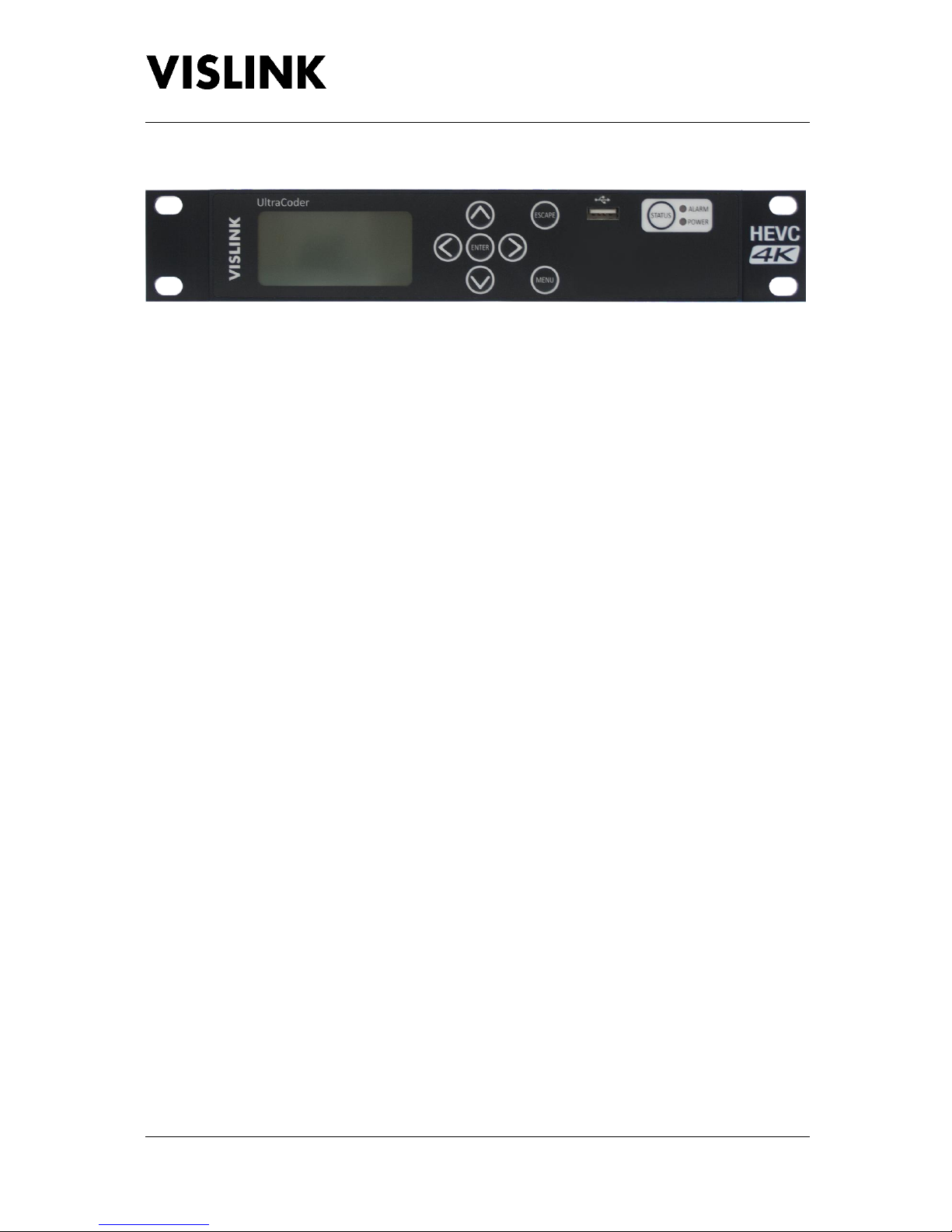
3. Front Panel
3.1. Buttons
3.1.1. MENU
Selecting this button will toggle between the menus and the AV lock status screen. It will also return
the menu screen to the main operating level from any point (as long as an item is not being edited).
3.1.2. ESCAPE
Selecting this button will return the menu screen to the level above the one being displayed if an
item is not being edited.
If an item is being edited, then this button will cancel the change being made and return to the
previously stored value.
3.1.3. STATUS
Selecting this button will change the menu screen to display the Alarms screen. Pressing the button
again will return the display to the screen that was previously being viewed.
3.1.3.1. ALARM LED
This LED will illuminate green when the system is operating as expected. If the system is generating
a warning, indicating that there is an issue to be aware of, then this LED will be illuminated in amber.
If the system is generating an error, then the LED will be illuminated red.
Details of the errors and warnings will be displayed in the Alarms screen, and which items are
displayed as alarms and their severity may be configured using the internal web interface.
3.1.3.2. POWER LED
This LED will be illuminated green when power is applied to the unit.
3.1.4. NAVIGATION (˄˅˂˃)
These buttons are used to navigate up, down, left and right around the menu screens.
3.1.5. ENTER
When editing an item this button will apply and store the selected value.

UltraCoder Operators Manual
Front Panel
Issue : 3 (16/12/2015) Page : 6
Ref : ULTC-ASUM-7001 Copyright © Vislink plc
3.2. Menu Screen
The menu screen provides the facility to configure all aspects of the unit via the front panel buttons
and also shows the AV lock states. See Menu Navigation (section 5 below) for full details of the
menus.
3.3. USB
This connector provides the facility for upgrading the unit’s software via a USB memory stick, as well
as downloading and uploading the unit configuration.
Please see Appendix A –Software Upgrade (section 7.1 below) for details on how to perform an
upgrade.
UltraCoder Operators Manual
Rear Panel
Issue : 3 (16/12/2015) Page : 7
Ref : ULTC-ASUM-7001 Copyright © Vislink plc
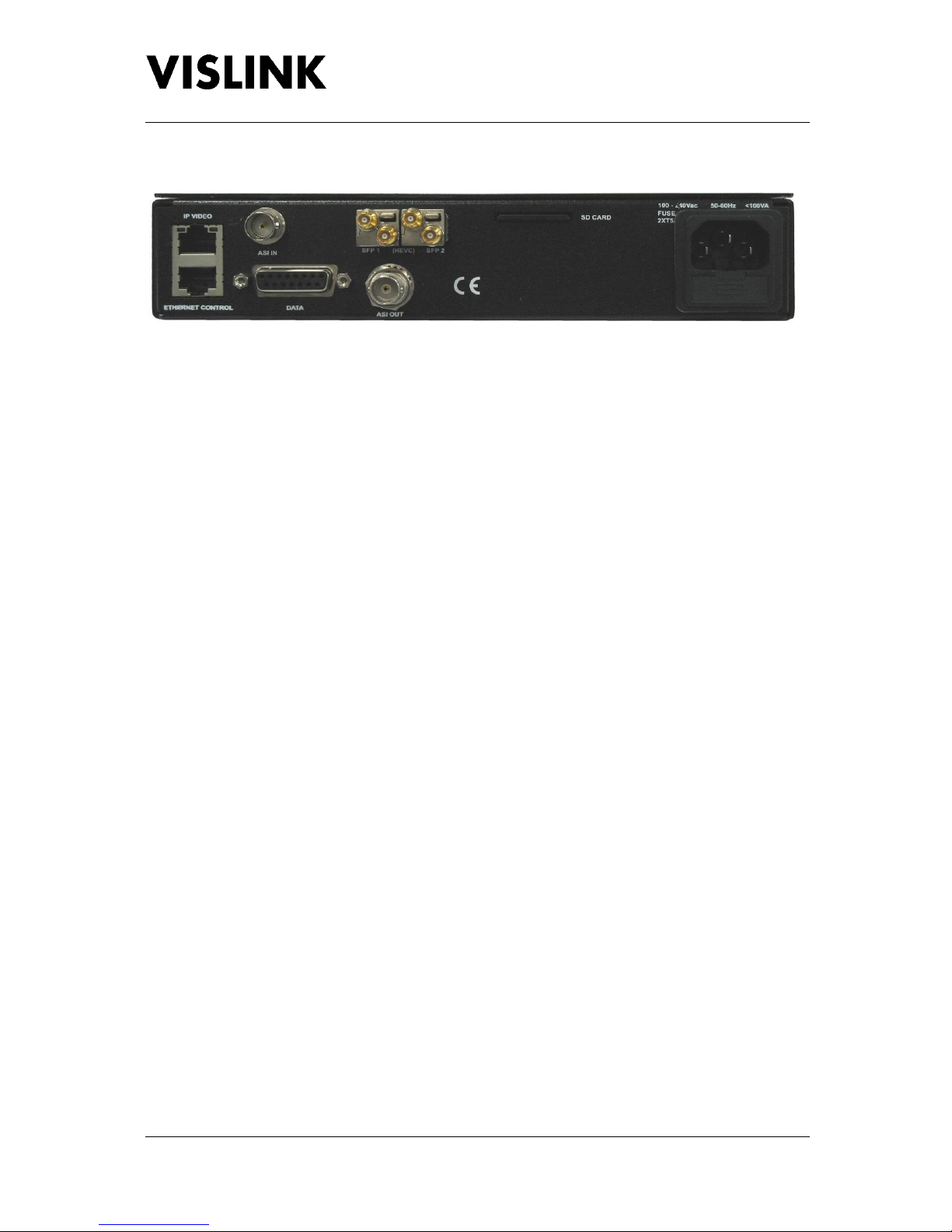
4. Rear Panel
4.1. IP Video
This connector is used for IP encapsulated ASI transport streams.
4.1.1. ASI TO IP
Two IP encapsulated ASI streams may be output, which are configured via the Channel 1 and
Channel 2 menus found under Unit Setup|IP Options|IP Out.
For each channel the destination IP address must be defined to state where the Ethernet packets are
to be directed, which is configured using the Destination IP option. The destination addresses may
be same, pointing to the same physical IP receiver, but if the two channels are in use, the
Destination Port numbers must be different. In this case, the IP receiver must be set to receive one
or the other ports.
Note that the error correction function makes use of two ports which will be the Destination Port
value + 2 and + 4, therefore if the port is set to 1000 for channel 1 then channel 2 must NOT use port
1002 or port 1004.
If the Destination IP addresses are different on each channel, the port addresses may be the same.
In this case, two IP receivers can receive the two possible IP outputs from the unit.
The two channels may be sourced independently, for example Channel 1 could be sourced from
external ASI and streamed to a location, whilst separately an encoded stream could be sent to
another location, using Channel 2.
Multiplexed ASI may also be streamed over a single IP path. These can be decoded separately at a
remote location using service names to extract the various services in the same manner as if it was a
direct ASI connection.
To cross networks, the IP video can be configured using the default gateway and sub-net mask setup
parameters, and the protocol used may be set to either RTP or UDP via the Encap option. Multicast
is also supported and is enabled by configuring the Destination IP address to a value in the multicast
address range 224.0.0.0 through 239.255.255.255 inclusive.
Approximately 80Mb/s total can be streamed over 100M Ethernet, dependent on the level of FEC
applied.

UltraCoder Operators Manual
Rear Panel
Issue : 3 (16/12/2015) Page : 8
Ref : ULTC-ASUM-7001 Copyright © Vislink plc
4.1.2. IP TO ASI
ASI may be de-encapsulated from an incoming RTP IP stream by selecting the appropriate port
number, as defined under the Unit Setup|IP Options|IP In menu. The external IP source should have
its destination address configured to match the value found under the IP Port Setup menu.
The received IP video may be included in a multiplexed output, which is configured under the Unit
Setup|Mux Options|Mux Inputs menu. The IP video may also be converted independently of the
encoding functions, by selecting the unit’s ASI output source selection to be IP.
4.2. Ethernet Control
This connector is used for remote control of the unit via SNMP or a web browser.
4.3. ASI In
This 75Ω BNC provides the facility to include an external ASI stream to be multiplexed with the
internal service of the unit.
To include the ASI In in a multiplexed output, the option needs to be enabled under the Unit
Setup|Mux Options|Mux Inputs menu.
4.4. Data
This connection is via a female 15way D-Type connector.
4.4.1. MPEG DATA
This connection is for future use for inserting data into the MPEG stream. Data may be inserted at
9600, 16200, or 38400 baud rates. The format is RS232 using the pins defined below.
Note that TX Data to external device may not be required.
4.4.2. STATUS RELAY
A pair of ground free relay contacts are also provided on this connector, to provide a summary alarm
status of the UltraCoder. Normally this is configured at the factory for an open circuit indicating a
fail.
This configuration may be reversed by the use of internal status link on the control PCB.
Parameters that can set the relay can be controlled via the web interface on the Alarm Mask page,
found under the Unit settings.
4.4.3. PIN OUTS
Pin
Signal
Description
Remark
1
NC
2
NC
3
NC
4
NC
5
Data Rx
RS232 MPEG data input to encoder

UltraCoder Operators Manual
Rear Panel
Issue : 3 (16/12/2015) Page : 9
Ref : ULTC-ASUM-7001 Copyright © Vislink plc
Pin
Signal
Description
Remark
6
Data TX
Not used
7
GND
8
NC
9
NC
10
NC
11
NC
12
NC
13
NC
14
Status Relay
Relay contact opens on fault
Internal link to swap NC/NO
15
Status Relay
Relay contact opens on fault
Internal link to swap NC/NO
4.5. SFP 1 & 2
Two SFP+ module slots supporting electrical and optical interfaces carrying four 3G HD-SDI (UHD) or
four independent HD-SDI connections.
4.6. ASI Out
This 75Ω BNC is used to provide an output ASI stream, which may be sent to another unit to form a
multiplex or used to drive an external modulator.
The source for the output connector may be either External ASI (the physical rear panel connector
for loop through applications), Extracted from IP, Video (all of the streams input to the video
encoder), or from the internal encoder (after the multiplexer).
ASI output format can be 188 or 204 byte mode when output is from the multiplexer.
4.7. SD Card
The SD card plugged into the rear of the unit is used for upgrading and licencing the encoder module
within the unit.
Stored on the SD card is an executable file, which can be used to configure the encoder parameters.
For upgrades a new version of the executable will be supplied. To perform the upgrade, the card
should be removed from the unit and accessed from a PC. The new executable should then be
copied onto the card and run, after which the card should be returned to the unit where it will
perform the upgrade. In all instances, the executable supplied on the SD card must be run from the
card itself in order that the files are created and stored in the correct place.
Note that the SD card must be present in the unit in order for it to operate, and that cards cannot be
swapped between units.
4.8. AC Power
Power in the range of 90 –264V AC is connected via 3 pin IEC connector. The total power
consumption is typically less than 100W.

UltraCoder Operators Manual
Rear Panel
Issue : 3 (16/12/2015) Page : 10
Ref : ULTC-ASUM-7001 Copyright © Vislink plc
Live and Neutral conductor fusing is employed. The two fuses integrated into the IEC connector
should be ceramic at T5A rating each.
External IEC mains lead must be un-plugged before removal of the lid –dangerous voltages
enclosed.

UltraCoder Operators Manual
Menu Navigation
Issue : 3 (16/12/2015) Page : 11
Ref : ULTC-ASUM-7001 Copyright © Vislink plc
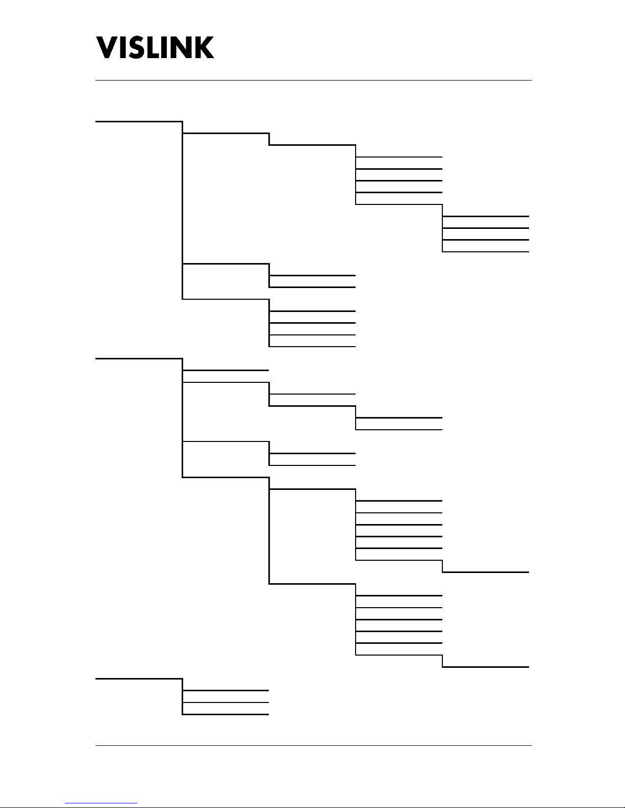
5. Menu Navigation
The tree views below describe the structure of the menus in the unit. Note that some menus
dynamically change dependent on the mode of operation, therefore not all options shown below
may be available at all times.
From the main menu screen there are four options: Encoder Setup; Audio Setup; Unit Setup; and,
System. The structure of each is shown below whereby emboldened items are editable options,
with details of each option following.
To move through the menus, use the Navigation (˄˅˂˃) buttons to select the parameter to change,
followed by the Enter button to select the next menu layer or to edit an item.
A prompt is given at the top of the screen showing the function of the highlighted menu option.
5.1. Encoder Setup
Video 1..4
Encoder
Video Format
Format
Video Input
Video Rate
Video Rate
Used Rate
H.265 Rate
Encoder
Configuration
Mode
Bit Depth
Delay
PIDS
Service
Video PID
PCR PID
PMT PID
MORE >
Prog Number
Scrambling
Scrambling
Type
Key
Injected ID
5.1.1. VIDEO 1..4
Dependent on the video format defined there will be either one or four encoder sectors. When a 4K
video format is selected, only one encoder sector will be visible, whereas for all other formats all
four sectors will be displayed.

UltraCoder Operators Manual
Menu Navigation
Issue : 3 (16/12/2015) Page : 12
Ref : ULTC-ASUM-7001 Copyright © Vislink plc
5.1.1.1. ENCODER
5.1.1.1.1. Video Format
5.1.1.1.1.1. Format
This option allows for the video format to be modified for Video-1 only. When a non-4K format is
selected all other video options will use the same value.
Available 4K formats are: 2160p/23.98, 2160p/24, 2160p/25, 2160p/29.97, 2160p/30, 2160p/50,
2160p/59.94 & 2160p/60.
Available non-4K formats are: 480i/29.97, 576i/25, 720p/50, 720p/59.94, 720p/60, 1080i/50,
1080i/59.94, 1080i/60, 1080p/23.98, 1080p/24, 1080p/25, 1080p/29.97, 1080p/30, 1080p/50,
1080p/59.94 & 1080p/60.
5.1.1.1.1.2. Video Input
This option defines whether the video input is in use for the encoding sector.
5.1.1.1.2. Video Rate
5.1.1.1.2.1. Video Rate
This item allows for the video bitrate for an individual encoder to be defined. Valid values range
from 0.5 to 25.0Mb/s.
Note that the combined bitrates for all four encoding sectors must be less than the H.265 Rate.
5.1.1.1.2.2. Used Rate
This item displays the current combined video rate in use for the currently active H.265 video
streams.
5.1.1.1.2.3. H.265 Rate
This item allows for the maximum bitrate for H.265 encoding to be defined.
Note that the maximum amount allowed for all the encoders combined must be no greater than
54Mb/s.
5.1.1.1.3. Encoder Configuration
5.1.1.1.3.1. Mode
This option allows for the Chroma to be set to either 4.2.0 or 4.2.2
5.1.1.1.3.2. Bit Depth
This option provides the ability to configure the bit depth to be either eight or ten.
5.1.1.1.3.3. Delay
This options allows for the video delay to be configured to either a half, one or three seconds.

UltraCoder Operators Manual
Menu Navigation
Issue : 3 (16/12/2015) Page : 13
Ref : ULTC-ASUM-7001 Copyright © Vislink plc
5.1.1.1.4. PIDs
5.1.1.1.4.1. Service
This item allows for the service name to be defined.
Note that the name is restricted to a maximum of twelve characters.
5.1.1.1.4.2. Video PID
This item allows for the Video PID to be defined for the encoding.
Note that valid values range from 32 to 8190.
5.1.1.1.4.3. PCR PID
This item allows for the Program Clock Reference PID to be defined for the encoding.
Note that valid values range from 32 to 8190.
5.1.1.1.4.4. PMT PID
This item allows for the Program Map Table PID to be defined for the encoding.
Note that valid values range from 32 to 8190.
5.1.1.1.4.5. MORE >
Select this option in order to view additional configurable PID options.
5.1.1.1.4.5.1. Prog Number
This item allows for the Program Number to be defined for the encoding.
Note that valid values range from 1 to 255.
5.1.1.2. SCRAMBLING
5.1.1.2.1. Scrambling
This option defines whether to apply BISS encryption to the encoded video.
5.1.1.2.2. Type
This item defines which of the two BISS modes should be used when encrypting the video. The type
can be set to either BISS 1 or BISS E, whereby with BISS 1 only the Key needs to be set, but with BISS
E both the Key and Injected ID must be configured.
5.1.1.2.3. Key
This item allows for the key to be defined. When editing the up and down buttons will change the
character, and the left and right buttons can be used to select which character to change.
Note that when BISS 1 is in use this key will be twelve characters long, whereas when using BISS E it
will be sixteen characters in length. Also, only hexadecimal characters may be entered (i.e. 0-9 and
A-F).

UltraCoder Operators Manual
Menu Navigation
Issue : 3 (16/12/2015) Page : 14
Ref : ULTC-ASUM-7001 Copyright © Vislink plc
5.1.1.2.4. Injected ID
This item allows for the injected ID to be entered when using BISS E encryption. This key is fourteen
characters long, and will only be displayed for editing when BISS E encryption has been selected.
5.2. Audio Setup
1..8
Encoder
Input
Standard
PID
Rate
5.2.1. 1..8
These menus allow for each of the eight audio pairs to be configured.
5.2.1.1. ENCODER
This option defines to which of the video streams being encoded the audio pair should be allocated.
Note that audio pairs must be allocated to video streams in pairs themselves, so that pairs one and
two, pairs three and four, pairs five and six, and pairs seven and eight are allocated to the same
encoder, and when editing a pair the corresponding pair’s encoder setting will automatically change
to the same value. Each of these pair of pairs may be allocated to the same encoder, or different
ones, for example:
Pair One and Two : Video-1 Encoder
Pair Three and Four : Video-2 Encoder
Pair Five and Six : Video-1 Encoder
Pair Seven and Eight : Video-4 Encoder
5.2.1.2. INPUT
This option provides the facility to select which SDI audio group is allocated to a pair, or to use test
tones.
As with the Encoder setting, the input selection must be allocated to the audio pairs in pairs, so that
pairs one and two, pairs three and four, pairs five and six, and pairs seven and eight are allocated to
the same input, and when editing a pair the corresponding pair’s input setting will automatically
change to the same group.
Each SDI group is composed of four audio channels, with the first two channels being allocated to
the first pair, and the second two channels being allocated to the second pair.
5.2.1.3. STANDARD
This option provides the ability to select which audio standard to use for encoding, or to disable the
audio pair.
Note that unlike the Encoder and Input configuration, this setting may be set independently for each
of the eight audio pairs.

UltraCoder Operators Manual
Menu Navigation
Issue : 3 (16/12/2015) Page : 15
Ref : ULTC-ASUM-7001 Copyright © Vislink plc
5.2.1.4. PID
This item allows for the PID for the Audio to be defined. Valid values range from 32 to 8140.
5.2.1.5. RATE
This item displays the bitrate that will be used to provide the audio, if enabled.
UltraCoder Operators Manual
Menu Navigation
Issue : 3 (16/12/2015) Page : 16
Ref : ULTC-ASUM-7001 Copyright © Vislink plc
5.3. Unit Setup
IP Options
IP Video Out
Channel 1..2
IP Output
Destination IP
Destination Port
Encap
MORE >
TS Pckts per IP
FEC
Dest. FEC d (row)
Dest. FEC l (col)
IP Video In
Port
Status
IP Port Setup
Address
Mask
Gateway
Traffic
Mux Options
Output
Mux Inputs
Video 1..4
MORE >
ASI In
IP In
ASI Output
ASI Out
ASI Out Mode
External Input PIDs
External ASI PIDs
Service
Prog Number
PMT
PCR
Video PID
MORE >
PID 1..8
External IP PIDs
Service
Prog Number
PMT
PCR
Video PID
MORE >
PID 1..8
Identifiers
Network
Network ID
TS PID
Table of contents
Other Vislink Media Converter manuals


