Vislink HDE-264 User manual
HDE-264
HD/SD Encoder
User and Technical Manual
Manual Part No. RD000461 Rev. A. March, 2012

Page 2
HDE-264 HD/SD Encoder User and Technical Manual
Copyright © 2012
Part number RD000461
Printed in U.S.A.
Authorized EU representative: Vislink PLC
Quality Certification Vislink is certified to ISO 9001:2008.
The Vislink trademark and other trademarks are registered trademarks in the United States and/or other countries.
Microsoft®, Windows®, and Internet Explorer® are registered trademarks of Microsoft Corporation in the United
States and/or other countries.
Proprietary Material The information and design contained within this manual was originated by and is the
property of Vislink. Vislink reserves all patent proprietary design, manufacturing, reproduction use, and sales rights
thereto, and to any articles disclosed therein, except to the extent rights are expressly granted to others. The
foregoing does not apply to vendor proprietary parts. Vislink has made every effort to ensure the accuracy of the
material contained in this manual at the time of printing. As specifications, equipment, and this manual are subject
to change without notice, Vislink assumes no responsibility or liability whatsoever for any errors or inaccuracies that
may appear in this manual or for any decisions based on its use. This manual is supplied for information purposes
only and should not be construed as a commitment by Vislink. The information in this manual remains the property
of Vislink and may not be used, disclosed, or reproduced in any form whatsoever, without the prior written consent of
Vislink. Vislink reserves the right to make changes to equipment and specifications of the product described in this
manual at any time without notice and without obligation to notify any person of such changes.
General Safety Information The following safety requirements, as well as local site requirements and regulations,
must be observed by personnel operating and maintaining the equipment covered by this manual to ensure
awareness of potential hazards. This equipment has been tested and found to comply with the limits for a Class
A digital device, pursuant to Part 15 of the FCC Rules. These limits are designed to provide reasonable protection
against harmful interference when the equipment is operated in a commercial environment. This equipment
generates, uses, and can radiate radio frequency energy. If not installed and used in accordance with the instruction
manual, it may cause harmful interference to radio communications. Operation of this equipment in a residential
area is likely to cause harmful interference in which case the user will be required to correct the interference at his
own expense.
About this Manual This manual is intended for use by qualified operators, installers, and service personnel. Users
of this manual should already be familiar with basic concepts of radio, video, and audio. For information about
terms in this manual, see Glossary of Terms and Abbreviations (Part No. 400576-1). Pay special attention to Notes,
Cautions, and Warnings.
Read NOTES for important information to assist you in using and maintaining the equipment
Follow CAUTIONS to prevent damage to the equipment.
Follow WARNINGS to prevent personal injury or death.
Symbols The following symbols may be on the equipment or in this manual:
or

Page 3
HDE-264 HD/SD Encoder User and Technical Manual
Table of Contents
Quick Start (Installed Rack Mount)....................................................4
Quick Start (Portable Operation).......................................................5
Introduction........................................................................................6
Features...............................................................................................................6
Operation (Rack Mount) ....................................................................7
AC Power Input....................................................................................................7
Power OFF/ON ....................................................................................................7
Power Indicator....................................................................................................7
Video Alarm..........................................................................................................7
SW Update...........................................................................................................7
Control Operation Table.......................................................................................7
Selecting the Preset............................................................................................ 8
Setting Video Bitrate ............................................................................................9
Setting the Audio................................................................................................10
Setting the Video................................................................................................ 11
Audio In..............................................................................................................12
Video In 1/2 (BNC).............................................................................................12
ASI Out (BNC) ...................................................................................................12
Ethernet (RJ-45) ................................................................................................12
RS232 (DB-9) Serial Data (Portable Unit Only) ................................................13
Power (4-Pin Lemo) Input (Portable Unit Only).................................................13
Remove and Replace Portable Unit/Rack Mount ...........................14
Rack Mount to Portable Unit..............................................................................14
Portable Unit to Rack Mount..............................................................................15
Mounting in a 19-Inch Rack...............................................................................16
Main Control Panel (Portable Operation) ........................................17
SAVE Button ......................................................................................................17
PRESET Button .................................................................................................17
Control Operation Table.....................................................................................18
Audio Input Levels .............................................................................................18
RF Output Power Level .....................................................................................18
Indicator LED Table ...........................................................................................19
PC Network Setup...........................................................................20
Web Browser Control Interface .......................................................22
Menu Bar ...........................................................................................................23
Change Password .............................................................................................23
Factory Settings.................................................................................................24
Streaming over IP ..............................................................................................25
Configuring Presets ...........................................................................................26
Presets - Recommended Encoder Settings ......................................................28
Board Information ..............................................................................................32
Firmware Upgrade.............................................................................................33
Specifications...................................................................................34
Video Encoding (H.264/14496-10) ....................................................................34
Video Resolution................................................................................................34
Video/IP Interfaces.............................................................................................34
Audio Input Interfaces........................................................................................34
Control and Management..................................................................................35
Physical and Power ...........................................................................................35
Environmental Conditions..................................................................................35
Notes ...............................................................................................36
Getting Support for Your Vislink Product.........................................37
Page 4
HDE-264 HD/SD Encoder User and Technical Manual
Quick Start (Installed Rack Mount)
Complete the following steps:
Connect your camera or other video signal source to suitable 75 Ohm BNC
connector cable and connect to encoder rear panel Video IN 1 or 2 input
connector.
Verify that the AC Power In cable from your 90 VAC - 264 VAC, 50-60 Hz power
source is connected to the rear panel AC Power In connector.
Verify that at least one of your rear panel ASI OUT connectors is connected to a
suitable 75 Ohm BNC connector cable and to your destination point (transmitter
input eg.). Or, if you are streaming IP out to Ethernet, ensure that you have a
suitable network cable connected to the rear panel RJ-45 Ethernet port and to your
destination point (PC LAN Port eg.).
Verify that your audio connections are made to the rear panel Land RAudio OUT
XLR connectors (if audio is required).
Turn ON (I) the front panel PWR rocker (I/O) switch. Allow 60 seconds for the
encoder to fully start-up. The front panel display will show Vislink - Encoder
Bootup Process during start-up.
Select your desired Preset. Press the front panel UP and Down keys to navigate
to the Preset screen. Press the Enter key to display the asterisk on the screen.
Then, use the UP and Down keys to navigate to the desired Preset number. Press
the Enter key to complete the selection.
Select your desired Video Mode. Press the front panel UP and Down keys to
navigate to the Video Mode screen. Press the Enter key to display the asterisk
on the screen. Then, use the UP and Down keys to navigate to the desired Video
Mode. Press the Enter key to complete the selection.
Select your desired Audio Mode. Press the front panel UP and Down keys to
navigate to the Audio Mode screen. Press the Enter key to display the asterisk
on the screen. Then, use the UP and Down keys to navigate to the desired Audio
Mode. Press the Enter key to complete the selection.
Select your desired Bitrate. Press the front panel Up and Down keys to navigate to
the Bitrate screen. Press the Enter key to display the asterisk on the screen. Then,
use the Left and Right keys to navigate to the digit to modify and then the Up and
Down keys to increase or decrease the value of that digit. Repeat for each digit.
Then, press the Enter key to complete the selection.
1.
2.
3.
4.
5.
6.
7.
8.
9.
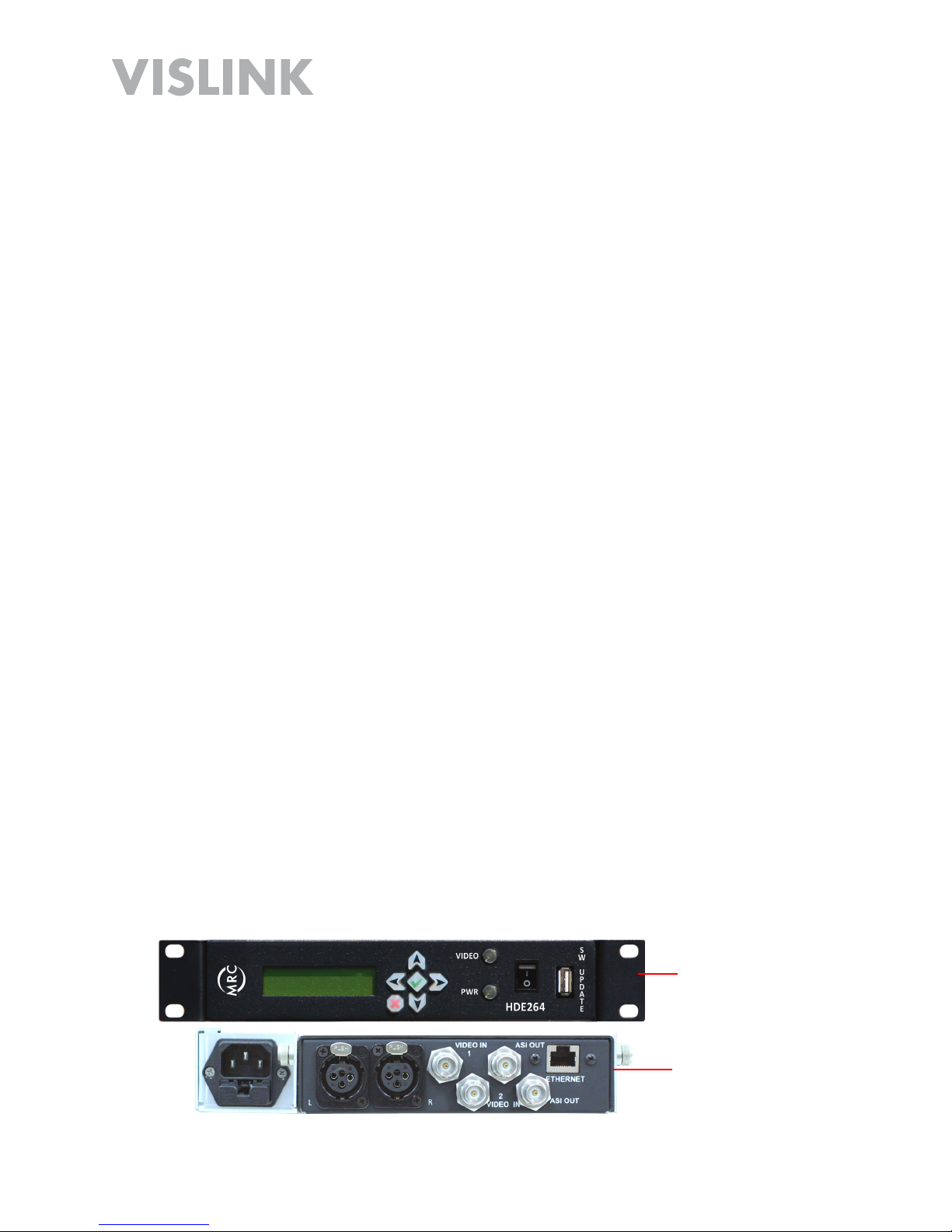
Front Panel
(Installed Rack
Mount)
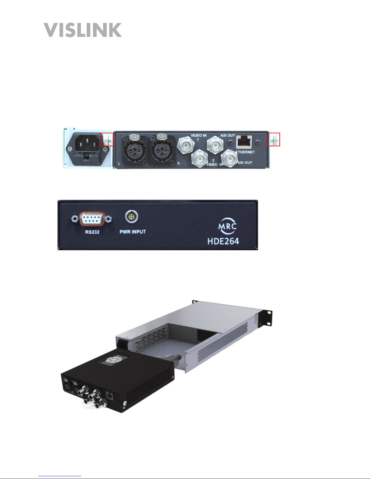
Rear Panel
(Installed Rack
Mount)
Page 5
HDE-264 HD/SD Encoder User and Technical Manual
Quick Start (Portable Operation)
Complete the following steps:
Connect your camera or other video signal source to suitable 75 Ohm BNC
connector cable and connect to encoder rear panel Video IN 1 or 2 input
connector.
Verify that the DC Power In cable from your +22 to +32 VDC Power Supply is
connected to the rear panel DC Power In 4-pin Lemo connector. There is no
ON/OFF Switch (in Portable configuration) so Power is ON when DC Input is
connected. Allow 60 seconds for the encoder to fully start-up. The front panel
display will show Vislink - Encoder Bootup Process during start-up.
Verify that at least one of your rear panel ASI OUT connectors is connected to a
suitable 75 Ohm BNC connector cable and to your destination point (transmitter
input eg.). Or, if you are streaming IP out to Ethernet, ensure that you have a
suitable network cable connected to the rear panel RJ-45 Ethernet port and to your
destination point (PC LAN Port eg.).
Verify that your audio connections are made to the rear panel Land RAudio OUT
XLR connectors (if audio is required).
Select your desired Preset using the Preset and UP/Down keys on the Main
Control Panel (see Main Control Panel section). Press the Save key.
If required, refer to Web Browser Control Interface section for Preset configuration
instructions.
1.
2.
3.
4.
5.
6.
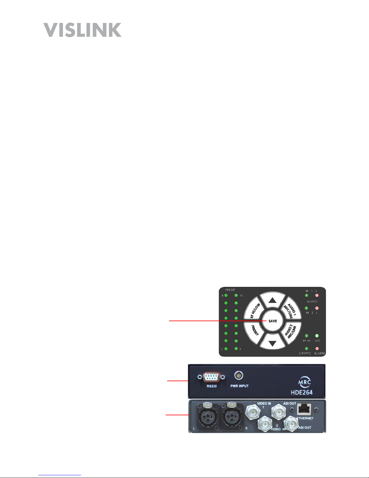
Main Control
Panel
(Top, Portable
Unit)
Front Panel
(Portable Unit)
Rear Panel
(Portable Unit)
Page 6
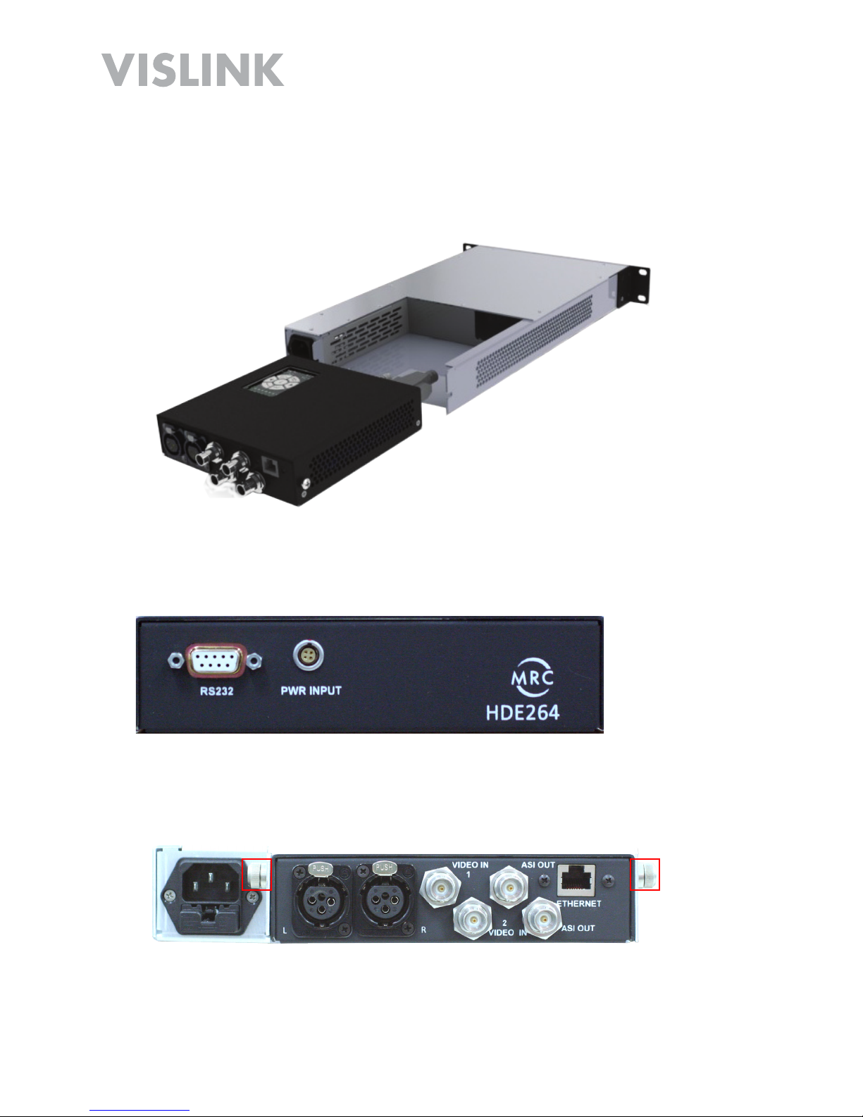
HDE-264 HD/SD Encoder User and Technical Manual
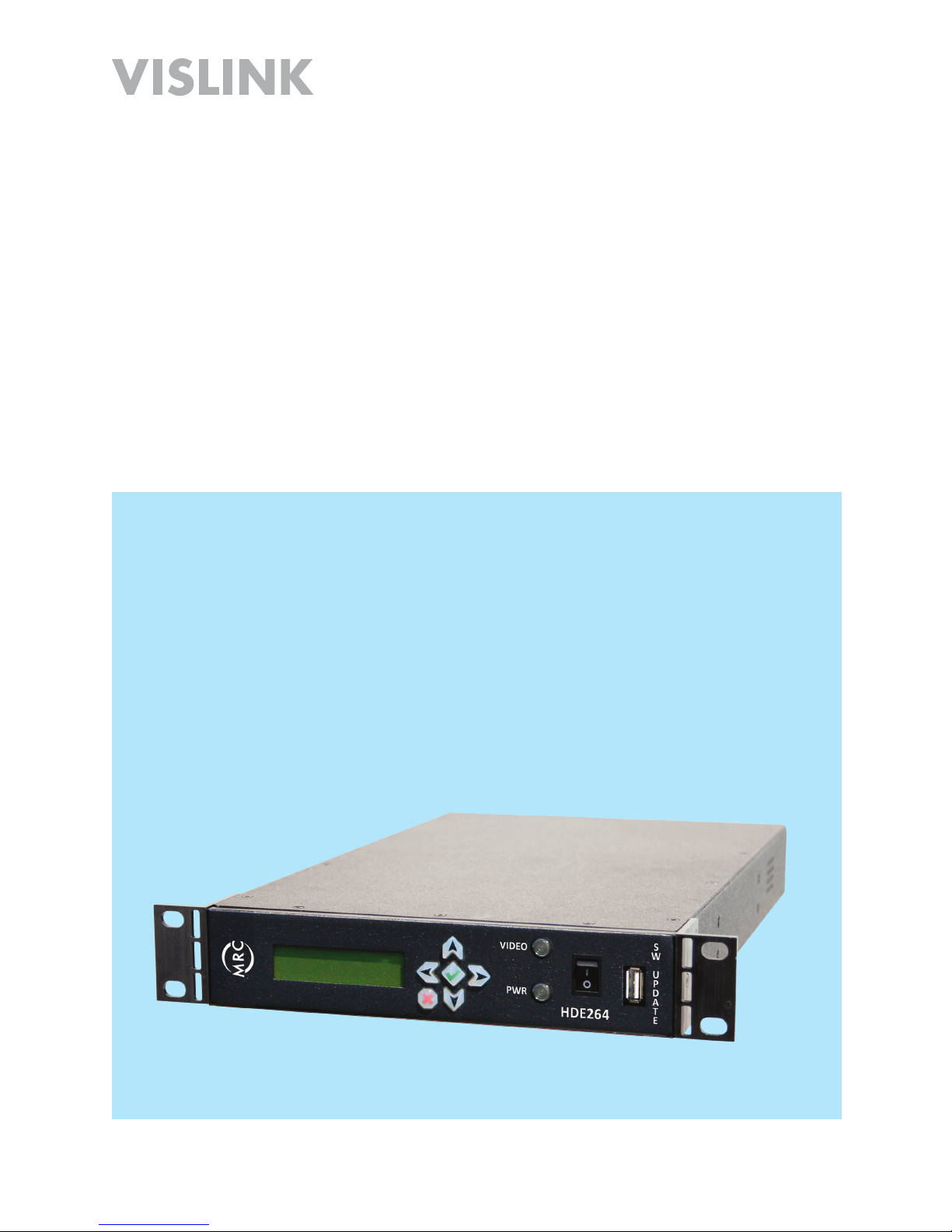
HDE-264 Encoder detaches from rack assembly for portable applications.
Introduction
The HDE-264 Digital Video Encoder is ideally suited for high quality 4:2:0 Main and
High Level Profile (L4.1) 8-bit H.264 (AVC) SD & HD video encoding for terresteral and
broadcast ENG and IP applications. The versatile, 1/2-width rack design allows the
Encoder to be detached from the rack assembly for portable applications.
The HDE-264 features high performance MPEG-4 encoding. The unit is designed with
both ASI and IP outputs. Both 1080i and 720p video resolution and a variety of video
input interfaces are supported, including a unique dual SD encoding format known as
Double Vision.
The HDE-264 Encoder is an ideal cost effective choice for broadcast video distribution,
live venue events, confidence monitoring, and video conferencing systems.
Features
HD/SD 4:2:0 MP/HP @ L4 Video Encoding
Selectable ASI & IP Outputs
IP Video Streaming
Dual SD Encoding
Detachable docked module for remote IP applications
Compact 1 RU 1/2 width rack mounting
Kits for 19” (full width) rack mounting (optional)
Page 7
HDE-264 HD/SD Encoder User and Technical Manual
Control Operation Table
Button Description
5Display next (up) increase
6Display next (down) decrease
4Select character (right)
3Select character (left)
aEnter (set)
XBack (escape)
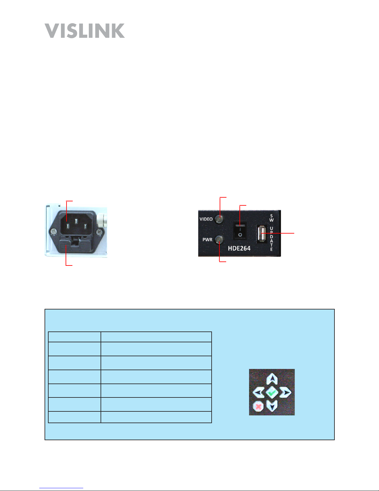
Front Panel
Controls
Video Alarm
Power Indicator
Power OFF/ON
SW Update
Future Use
(USB)
Operation (Rack Mount)
AC Power Input
The AC Power Input (90 VAC - 264 VAC, 50-60 Hz) and two Fuses (2A, 250 V fast
blow) are located on the rear panel (Rack Mount mode).
Power OFF/ON
The Power OFF/ON is the main power switch while in rack mount operation.
Power Indicator
The Power Indicator lights when AC power is connected and the Power OFF/ON switch
is set to ON.
Video Alarm
The Video Alarm indicator lights when a valid signal is not present.
SW Update
This USB SW Update connector is for future use.
As a rack mounted unit, operation from the front panel is accomplished by means of the
Front Panel Controls (below).
AC Power In
Fuses (2)
Front Panel
Rear Panel

Page 8
HDE-264 HD/SD Encoder User and Technical Manual
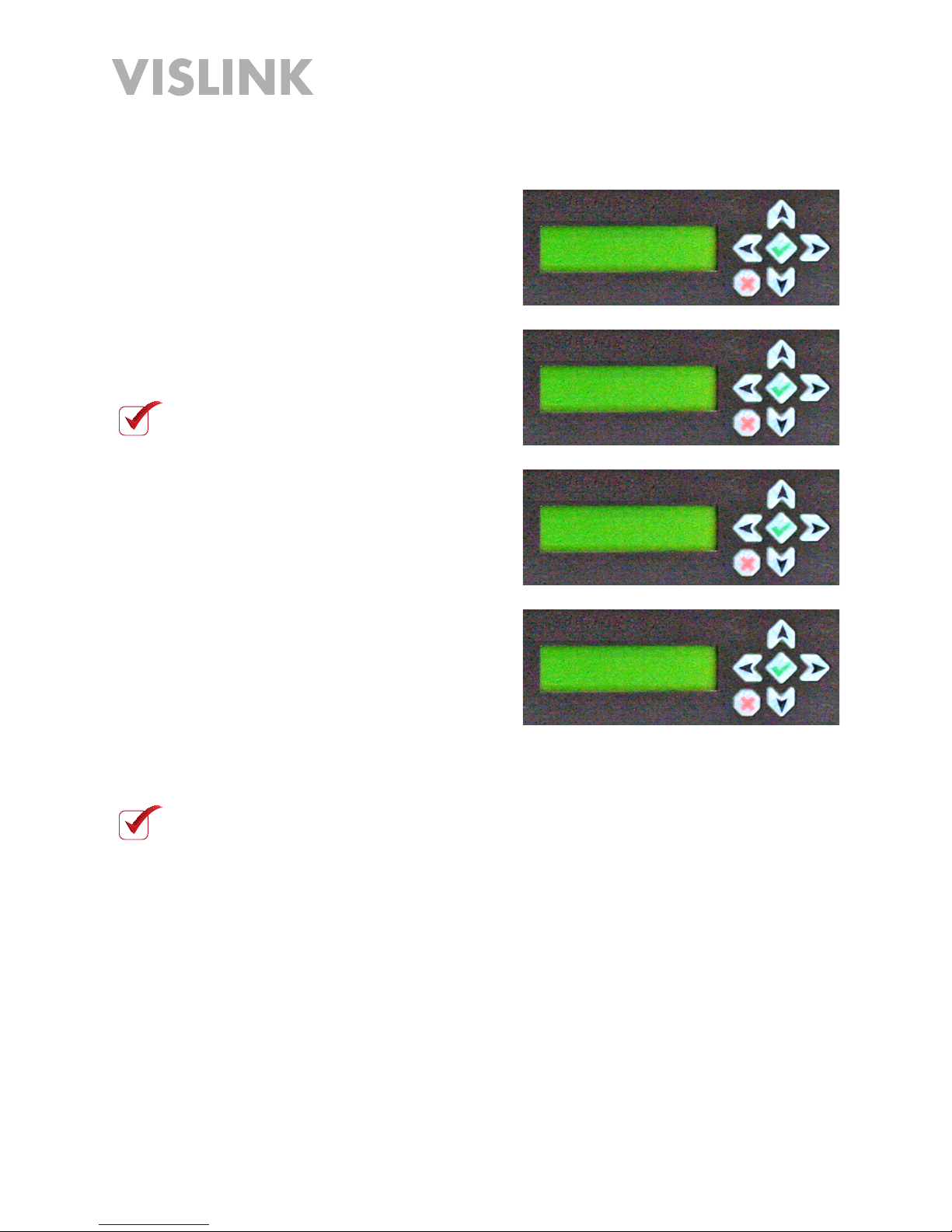
Selecting the Preset
Complete the following steps.
Press the 5 or 6 key.
The Preset Screen Displays.
Press the akey.
Press the 5 or 6 key.
Press the akey to set.
1.
2.
3.
4.
Preset #:
1
Preset #:
1 *
Preset #:
16 *
Preset #:
16
NOTE: The asterisk * indicates
programming mode.

Page 9
HDE-264 HD/SD Encoder User and Technical Manual
Setting Video Bitrate
Complete the following steps.
Press the 5 or 6 key.
The Bitrate Screen Displays.
Press the akey.
Press the 3 4 keys to navigate.
Press the 5 6 keys to adjust.
Press the akey to set.
1.
2.
3.
4.
5.
BitRate (Mbps):
08.229
BitRate (Mbps):
08.229 *
BitRate (Mbps):
07.229 *
BitRate (Mbps):
07.229
NOTE: The asterisk * indicates
programming mode.
NOTE: Valid settings are from 2 Mbps to 15 Mbps only.
NOTE: Setting these parameters will save the changes to the active preset.
Page 10
HDE-264 HD/SD Encoder User and Technical Manual
Setting the Audio
Complete the following steps.
Press the 5 or 6 key.
The Audio Mode Screen Displays.
Press the akey.
Press the 5 6 keys to adjust.
Press the akey to set.
1.
2.
3.
4.
Audio Mode :
HD-SDI
Audio Mode :
HD-SDI *
Audio Mode :
Analog *
Audio Mode :
Analog
NOTE: The asterisk * indicates
programming mode.
NOTE: Setting these parameters will save the changes to the active preset.

Page 11
HDE-264 HD/SD Encoder User and Technical Manual
Setting the Video
Complete the following steps.
Press the 5 or 6 key.
The Video Mode Screen Displays.
Press the akey.
Press the 5 6 keys to adjust.
Press the akey to set.
1.
2.
3.
4.
Video Mode :
1080i59.94
Video Mode :
1080i59.94 *
Video Mode :
720p60 *
Video Mode :
720p60
NOTE: The asterisk * indicates
programming mode.
NOTE: Setting these parameters will save the changes to the active preset.
Page 12
HDE-264 HD/SD Encoder User and Technical Manual
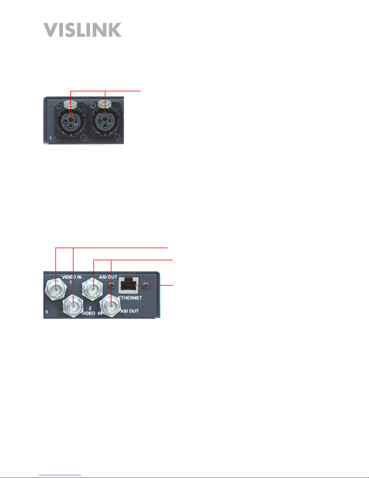
Audio In L/R (XLR)
Video In 1/2 (BNC)
ASI Out (BNC)
Ethernet (RJ-45)
Audio In
Two Audio Input 3-pin XLR connectors are located on the rear panel for 600 Ohm
balanced input.
Video In 1/2 (BNC)
Two Video In (BNC) connectors are located on the rear panel for composite input.
ASI Out (BNC)
Two ASI Out (BNC) connectors are located on the rear panel for digital output.
Ethernet (RJ-45)
An Ethernet (RJ-45) connector is located on the rear panel for Web Browser Control
Interface connectivity, as well as for streaming IP output.
Page 13
HDE-264 HD/SD Encoder User and Technical Manual
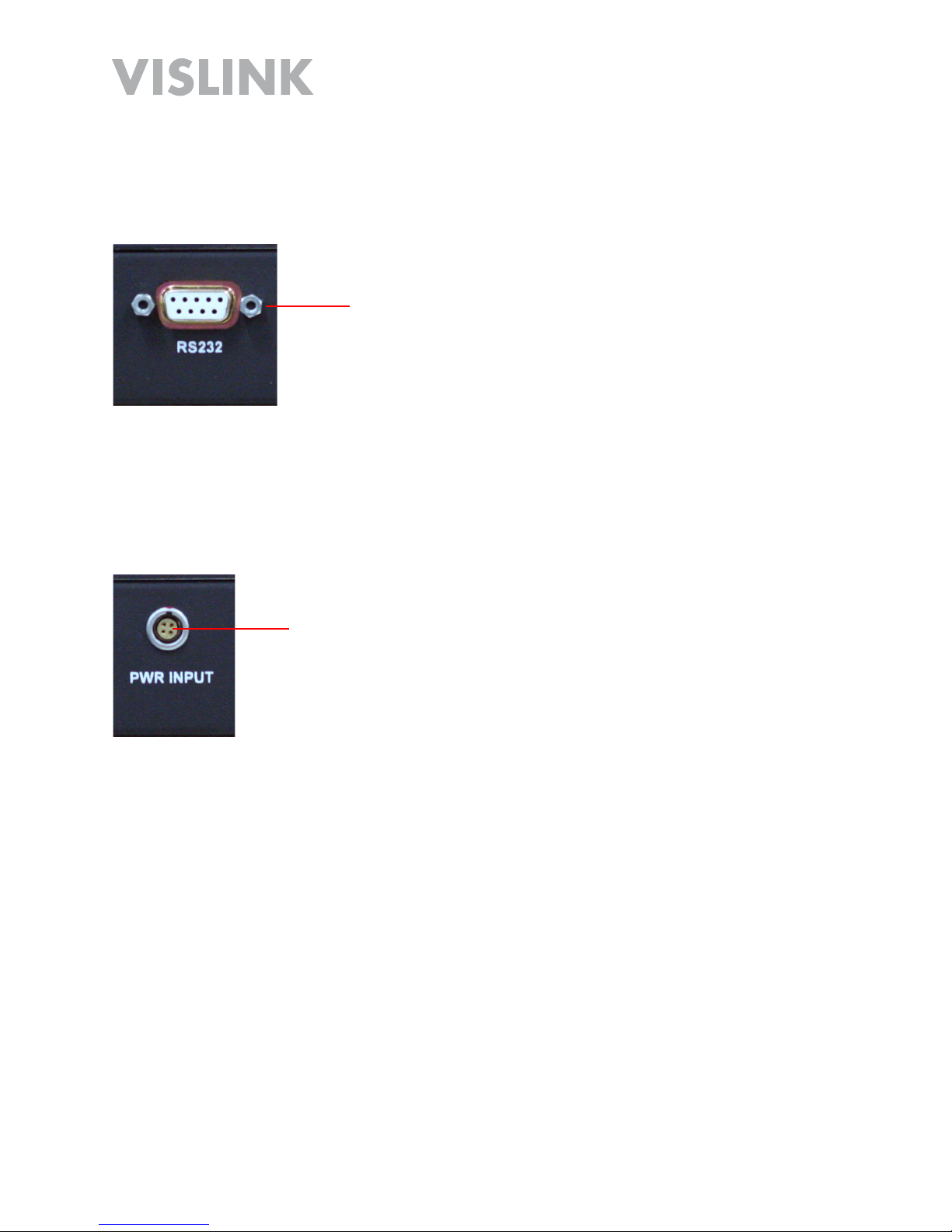
Power Input
(4-Pin Lemo)
RS232 (DB-9) Serial Data (Portable Unit Only)
An RS232 (DB-9) Serial Data connector is located on the rear panel of the portable unit
and is connected but not visible in rack mounted applications.
Power (4-Pin Lemo) Input (Portable Unit Only)
A (4-Pin Lemo) Input DC Power connector is located on the rear panel of the portable
unit and is connected but not visible in rack mounted applications.
RS232 Serial
Data (DB-9)
Page 14
HDE-264 HD/SD Encoder User and Technical Manual
Remove and Replace Portable Unit/Rack Mount
Rack Mount to Portable Unit
Complete the following steps:
Turn OFF power and remove power connection.
Remove rack mount unit from rack.
With unit on benchtop, losen two captive thumbscrews on the rear panel.
Slide portable unit until you can access the two cables on the back.
Carefully remove the Lemo Power (pull ferrule) and DB-9 serial (two captive
thumbscrews) cables from unit.
Remove portable unit.
1.
2.
3.
4.
5.
6.
Page 15
HDE-264 HD/SD Encoder User and Technical Manual
Portable Unit to Rack Mount
Complete the following steps:
Turn OFF power and remove DC power connection.
Line-up the portable unit as shown with connectors facing in.
Connect the DB-9 serial (two captive thumbscrews) and the Lemo Power (pull
ferrule) cables to the portable unit.
Slide portable unit in until the screw holes line-up with the two captive thumbscrews
on the rear panel. Carefully place the cables so they are not pinched.
Tighten the two captive thumbscrews on the rear panel to secure the installation.
1.
2.
3.
4.
Page 16
HDE-264 HD/SD Encoder User and Technical Manual
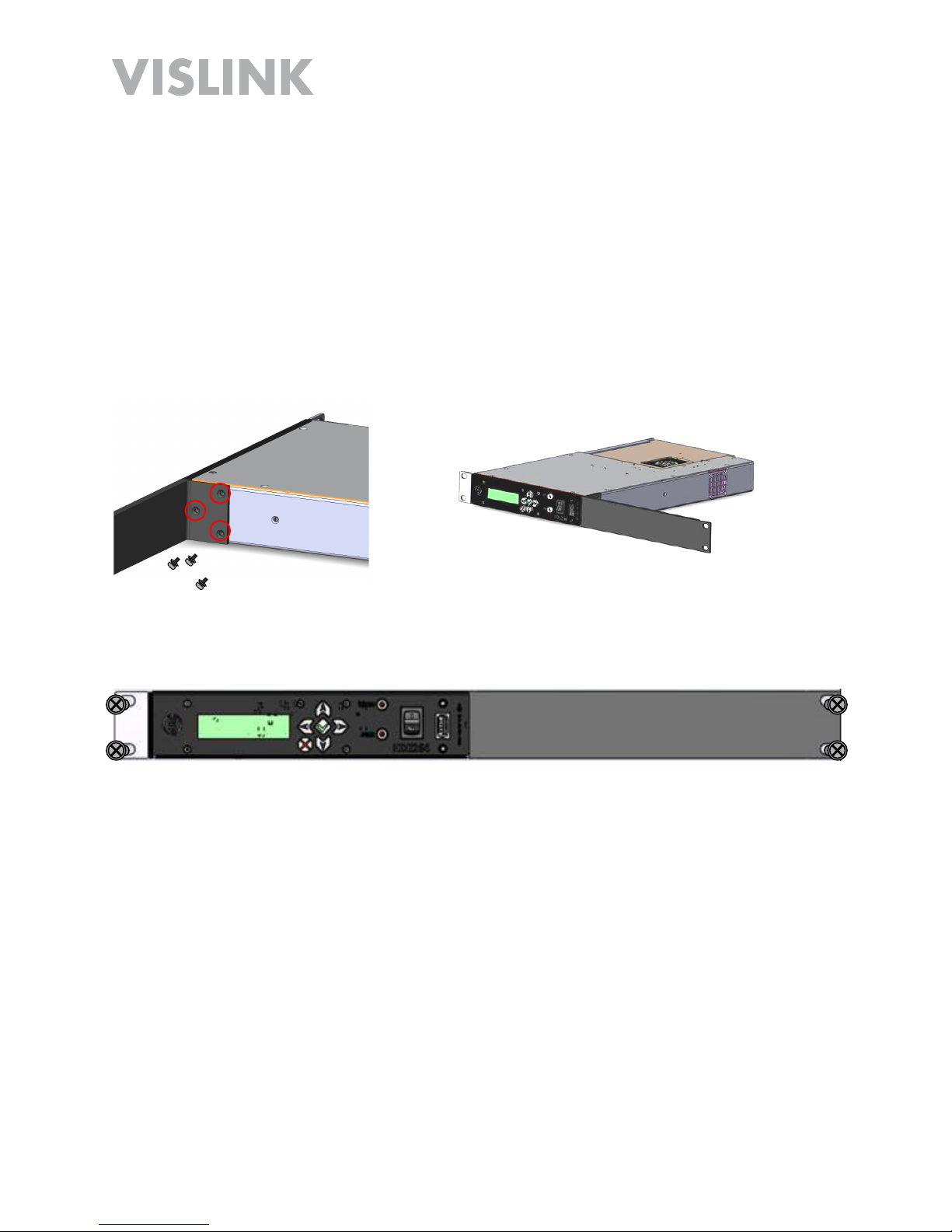
Mounting in a 19-Inch Rack
The HDE-264 is setup to mount in a portable, half-width rack. For installation in a
standard 19-inch rack, you will need to order the optional Extension Bracket Kit, Part
number 9005434 from your Vislink Sales Representative or from Customer Service.
Install the rack-mount unit into the 19-inch rack using the (optional) Extension Bracket
Kit as described below:
Remove either the left or right (shown) mounting bracket from the HDE-264 by
removing the four M6 Philips screws.
In it’s place, attach the Extension Bracket using the three 4-40 Philips screws
provided.
Install the unit with the Extension Bracket Kit installed into your 19-inch rack using
your four standard mounting screws.
Connect power and other connections to the rear panel as given in the Quick Start.
1.
2.
3.
4.

Page 17
HDE-264 HD/SD Encoder User and Technical Manual
Main Control Panel (Portable
Operation)
The Main Control Panel is located on the top of the unit and
provides both controls and indicators. Selection of presets
along with selecting basic operational settings and viewing
alarms are all available on the Control Panel. The panel
contains an LED Dark Timer that turns OFF LEDs after a 10
second delay. All LEDs are momentarily activated when the
unit is first powered ON.
SAVE Button
To save new settings including Audio Mic/Line and Preset,
you must press the SAVE Key to complete the task.
PRESET Button
The HDE-264 has up to 16 pre-configured* PRESETS in
memory that include settings such as frequency and power
output mode. To select a Preset (1 - 16), complete the
following steps:
Press the PRESET key. The currently selected preset
LED illuminates.
Press the Up ▲or Down ▼arrow keys to choose the
new preset you want.
The preset LED illuminates to indicate which preset was
selected. Press SAVE to complete.
NOTE: The HDE-264 recalls the most recently
saved audio input setting when it is powered up.
NOTE: If the SAVE key is not pressed within 5
seconds of the new setting, the audio input level
returns to the most recently used value and the
selection mode is canceled.
*PRESETS are configured using the Web Browser Control Interface.
1.
2.
3.

Page 18
HDE-264 HD/SD Encoder User and Technical Manual
Audio Input Levels
The Audio Input Levels control is not used in this
application.
RF Output Power Level
The RF Output Power Level control is not used in this
application.
Control Operation Table
Button Description
RF HI/LOW N/A
▲Move UP through presets/levels.
▼Move DOWN through presets/levels.
AUDIO 1 MIC/LINE N/A Line only.
AUDIO 2 MIC/LINE N/A Line only.
PRESET Press to enter Preset mode. The PRESET LED indicates the
current preset. Press the UP ▲ or DOWN ▼ button to select
one of the stored Presets (1 - 16). Press SAVE to confirm the
new setting.
SAVE Confirms the new setting.

Page 19
HDE-264 HD/SD Encoder User and Technical Manual
Indicator LED Table
Indicator Description Suggested Actions
PRESET Displays the selected
PRESET (1 - 16).
Select the desired PRESET.
AUDIO Green when enabled.
Dark when disabled.
M=MIC L=LINE
Select the desired AUDIO setting.
RF HI N/A N/A
VID Green when a valid video
signal is present. Dark
when no valid video
signal is present. (Valid
video can be NTSC or
PAL analog composite,
as well as ASI or HD-SDI
digital signal.)
Check the video camera/source and
cabling to ensure the video signal is
reaching the encoder. (Signal has to
match what preset is selected and
what is configured in that preset.)
ALARM Red when an alarm
occurs. Dark when no
alarm present.
Connect encoder to PC via the
Ethernet interface to diagnose the
source of the alarm.
CRYPTO Green indicates
encryption is enabled and
encoder is transmitting
the encryption code
associated with the
preset. Dark indicates
encryption is disabled.
Verify whether encryption is required
for the selected preset.
Verify that encryption is properly
configured.

Page 20
HDE-264 HD/SD Encoder User and Technical Manual
PC Network Setup
Before connecting to the encoder using the Ethernet port on your Windows PC (via the
Web Browser Control Interface described in the next section) you must first configure
your PC as described in the steps given below.
NOTE: Windows 7 is shown here. Other versions of Windows may vary slightly.
From Windows Control Panel, go to Network and Sharing Center.
Click on Change Adapter Settings.
1.
2.
3. Right click the Local Area Connection icon and select Properties.
The Network Connections window displays.
Table of contents
Other Vislink Media Converter manuals


