Vislink DVE6100 User manual

Vislink, Waterside House, Earls Colne Business Park, Colchester, Essex, CO6 2NS, UK
Telephone: +44 (0)1442 431300 ●Facsimile: +44 (0) 1494 775356 ●Email: sales@vislink.com ●Website: www.vislink.com
Company Registered in England & Wales no. 10523708 ●VAT registration no. GB 260 012 169
Registered Office: Waterside House, Earls Colne Business Park, Colchester, Essex, CO6 2NS, UK
DVE6100
UHD/HD/SD Video
Encoder - Modulator
User Manual

Issue No: 1 Page: ii
Ref: DVE6-ASUM-70xx Copyright © 2019 IMT and Vislink are Vislink Technologies Inc. companies
Document Disclaimer
The information contained in this manual remains the property of Vislink and
may not be used, disclosed or reproduced in any other form whatsoever without
the prior written permission of Vislink.
Vislink reserves the right to alter the equipment and specification appertaining to
the equipment described in this manual without notification.
This document is supplied on the express terms that it is to be treated as
confidential and that it may not be copied, used or disclosed to others for any
purpose except as authorized by Vislink.
Conventions
NOTE: Notes show to convey additional information.
CAUTION: Cautions show where potential equipment damage could occur.
WARNING: Warnings show where there is potential for personal danger or risk of
death. Read all warnings and understand them before carrying out
work on any equipment. This includes peripherals and any related
equipment in use. The danger is real and not reading and
understanding the warning could lead to injury, harm or potential
death.
Service/Support Contacts:
Register for support:
Worldwide: https://support.imt-solutions.com
Call for support:
Worldwide: +44 1442 431410
USA: +1 978 330 9292
When contacting Technical Support, please include the model and serial number
of the unit (located on a label on the bottom of each unit and found in the
software) and the approximate date of purchase.

Issue No: 1 Page: iii
Ref: DVE6-ASUM-70xx Copyright © 2019 IMT and Vislink are Vislink Technologies Inc. companies
Document History
Version
Date
Modification
Firmware Version
1
10/09/2019
First release of document.

Issue No: 1 Page: iv
Ref: DVE6-ASUM-70xx Copyright © 2019 IMT and Vislink are Vislink Technologies Inc. companies
Table of Contents
1. General Information.............................................................................................. 7
1.1. General Safety Information ..................................................................................................7
1.2. Disposal Instructions...............................................................................................................7
1.3. Environmental ......................................................................................................................... 7
1.4. Health & Safety ....................................................................................................................... 8
2. Introduction ........................................................................................................... 9
3. Specifications....................................................................................................... 11
3.1. Physical...................................................................................................................................11
3.2. Inputs.......................................................................................................................................11
3.3. Outputs ...................................................................................................................................11
3.4. Remote Control / Monitoring / HPA Control ....................................................................12
3.5. Video .......................................................................................................................................12
3.5.1. RF....................................................................................................................................... 13
3.5.2. IP Video (Future option).................................................................................................. 14
4. Front Panel Overview......................................................................................... 15
4.1. Front Panel.............................................................................................................................15
4.2. Selection Keys ....................................................................................................................... 15
4.3. Menu Scroll Keys ...................................................................................................................15
4.4. Hot Keys .................................................................................................................................15
4.5. LEDs.........................................................................................................................................16
4.5.1. Alarm................................................................................................................................. 16
5. Rear Panel ............................................................................................................ 17
5.1. Monitor –Control HPA Control & MPEG Data.................................................................. 17
5.1.1. 15-Way D-Type (Female) Pin Definition....................................................................... 17
5.2. MPEG User Data.................................................................................................................... 17
5.3. HPA Control............................................................................................................................18
5.4. Status Relay ...........................................................................................................................18
5.5. AC Power................................................................................................................................18
5.6. RF1 Output .............................................................................................................................19
5.7. RF2 Output.............................................................................................................................19
5.8. ASI Input .................................................................................................................................19
5.9. Combiner IN ...........................................................................................................................19
5.10. Ethernet/USB Ports ..............................................................................................................20
5.11. IP Video (future option) .......................................................................................................20
5.11.1. ASI to IP Video............................................................................................................... 20
5.11.2. IP to ASI.......................................................................................................................... 20
6. Operation Guide .................................................................................................. 21
6.1. Powering the Unit.................................................................................................................21
6.1.1. External Connections ...................................................................................................... 21
7. Menu Navigation ................................................................................................. 23
7.1.1. Modulator Menu...............................................................................................................23
7.1.1.1. Setup ..............................................................................................................................23
7.1.1.2. Status .............................................................................................................................24
7.1.1.3. BUC.................................................................................................................................24

Issue No: 1 Page: v
Ref: DVE6-ASUM-70xx Copyright © 2019 IMT and Vislink are Vislink Technologies Inc. companies
7.1.1.4. 10MHz Reference..........................................................................................................24
7.1.1.5. 18V Supply .....................................................................................................................24
7.1.2. Video .................................................................................................................................25
7.1.2.1. Settings ..........................................................................................................................25
7.1.2.2. SDI 1-4............................................................................................................................27
7.1.3. Audio .................................................................................................................................27
7.1.4. ASI OUT.............................................................................................................................27
7.1.5. MUX (future).....................................................................................................................27
7.1.6. USER DATA (future option) ............................................................................................27
7.1.7. HPA CONTROL (future option).......................................................................................28
7.1.8. Unit Setup.........................................................................................................................28
7.1.8.1. Presets ...........................................................................................................................28
7.1.8.2. Control ...........................................................................................................................28
7.1.8.3. Defaults..........................................................................................................................28
7.1.8.4. Licenses .........................................................................................................................28
7.1.8.5. Time & Date...................................................................................................................28
7.1.9. Support. ............................................................................................................................29
7.1.9.1. Versions .........................................................................................................................29
7.1.9.2. Diagnostics ....................................................................................................................29
7.1.9.3. Contact...........................................................................................................................29
8. Licenses & Upgrades ........................................................................................... 31
8.1. Licensing.................................................................................................................................31
8.2. Upgrades ................................................................................................................................31
Table of Figures
Figure 4-1 DVE6100 Front Panel Overview ........................................................................... 15
Figure 5-1 Rear Panel Overview............................................................................................... 17
Figure 8-1 Supported Modulator Modes.................................................................................. 33
Figure 8-2 DVBS Supported Modulations ................................................................................ 34
Figure 8-3 DVBS2 Supported Modulations.............................................................................. 34

Issue No: 1 Page: vi
Ref: DVE6-ASUM-70xx Copyright © 2019 IMT and Vislink are Vislink Technologies Inc. companies
This page is intentionally unused.

Template Operators Manual
General Information
Issue No: 1 Page: 7
Ref: DVE6-ASUM-70xx Copyright © 2019 IMT and Vislink are Vislink Technologies Inc. companies
1. General Information
1.1. General Safety Information
To ensure awareness of potential hazards, all personnel concerned with the
operation or maintenance of the equipment must study the information that
follows, together with local site regulations.
WARNING: RF Power Hazard: High levels of RF power can be present satellite
communication systems. Exposure to RF or microwave power can
cause burns and may be harmful to health.
WARNING: Avoid standing in front of a dish and never look into the open end of
a waveguide or cable where RF power may be present.
CAUTION: We strongly recommended that you return any equipment requiring
RF servicing to Vislink.
WARNING: GaAs / BeO Hazard: Certain components inside the equipment
contain Gallium Arsenide and Beryllium Oxide that are toxic
substances. Whilst safe to handle under normal circumstances,
individual components must not be cut, broken apart, incinerated or
chemically processed. In the case of Beryllium Oxide, a white ceramic
material, the principal hazard is from the dust or fumes, which are
carcinogenic if ingested, inhaled or entering damaged skin.
Please consult your local authority before disposing of these components.
WARNING: Tantalum Capacitors: When subjected to reverse or excess forward
voltage, ripple current or temperature these components may rupture
and could potentially cause personal injury.
CAUTION: This system contains MOS devices. To prevent accidental damage,
employ Electro-Static Discharge (ESD) precautions.
1.2. Disposal Instructions
DO NOT dispose of any of the supplied equipment as household waste. The
supplied equipment is not biodegradable in landfill sites. For safe disposal of the
supplied equipment, take it to your local (council/authority) environmental waste
site. For details, contact your local authority/recycling center.
NOTE: In Europe dispose of all equipment in accordance with the European
Environmental directive.
1.3. Environmental
CAUTION: Protect the unit from dripping or splashing water/fluids. When used
outdoors, protect the unit using a rain cover.

Template Operators Manual
General Information
Issue No: 1 Page: 8
Ref: DVE6-ASUM-70xx Copyright © 2019 IMT and Vislink are Vislink Technologies Inc. companies
1.4. Health & Safety
WARNING: Any transmitting equipment, radiating power at frequencies of 100
kHz and higher, has the potential to produce thermal and athermal
effects upon the human body.
To be safe:
1. Do not stand or walk in front of any antenna or allow anyone else to do so.
2. Do not operate any RF transmitter or power amplifiers with any covers
removed and do not allow anyone else to do so.

Template Operators Manual
Introduction
Issue No: 1 Page: 9
Ref: DVE6-ASUM-70xx Copyright © 2019 IMT and Vislink are Vislink Technologies Inc. companies
2. Introduction
The Vislink DVE6100 is a compact 4K multi-format, multi-channel exciter. The
compact, lightweight design suits flyaway and vehicle mounted applications.
The DVE6100 provides superb satellite bandwidth efficiency, utilizing the latest
HEVC video compression and DVB-S2X satellite modulation technology. The
DVE6100 provides a 50% reduction in leased satellite bandwidth compared to
MPEG-4 and DVB-S2, reducing satellite OPEX.
As a multi-format encoder, the DVE6100 provides the ability to encode video of
all resolutions from SD to 4K (including High Dynamic Range). The multi-channel
capability of the unit allows it to encode up to four HD-video services in HEVC,
providing a flexible, channel-dense solution.
Encoder modes are selectable between:
MPEG2
H.264
HEVC
RF modulation schemes are selectable between:
DVBS
DVBS2
DVBS2X.

Template Operators Manual
Introduction
Issue No: 1 Page: 10
Ref: DVE6-ASUM-70xx Copyright © 2019 IMT and Vislink are Vislink Technologies Inc. companies
This page is intentionally unused.
Template Operators Manual
Specifications
Issue No: 1 Page: 11
Ref: DVE6-ASUM-70xx Copyright © 2019 IMT and Vislink are Vislink Technologies Inc. companies
3. Specifications
3.1. Physical
Dimensions
1RU ½ width chassis x 350 mm deep
Weight
1.8 Kg approx.
Power Connector
3-Pin IEC plug with dual fusing
AC Supply
100-240V AC 47 to 63 Hz @ <70 VA
Temperature Range
0 to +50°C (32oF to 122oF) operating
–20 to +80°C (-4oF to 1760oF) storage
Humidity
95% max non condensing
Status, HPA Control
15-Way D-type Female
Ethernet Control & IP Video
RJ45
USB Port
Female type A
Video, ASI, Connections
Mini HD SFP / BNC 75R
L-Band RF out, L-Band RF
monitor
N-Type 50R
L-Band RF Combiner
TNC 50R
3.2. Inputs
SDI on SFP
PAL / NTSC serial digital video to ITU-R BT.656 /
ANS I / SMPTE 259M @ 270Mb/s. 16 channels
(eight stereo pairs) embedded audio supported
(only 4 compressed) –75R
HDSDI on SFP
To SMPTE 292M @ 1.485 Gbit/s
ASI (Re-mux option) [future]
75R to ISO / IEC 13818-2 188bytes
L-Band Combiner
6dB+/-2dB passive coupler into main L-Band
output
3.3. Outputs
L-Band
50R, 950 –2150MHz +/-0.75dB, +5dBm 40dB
control;
L-Band MONITOR
50R, 30dB+/-3dB less than main L-Band output
ASI
75R, to ISO/IEC 13818-2 188bytes constant rate.
DC on L-band
18V +/-1V @ 1A max.
Precision 10MHz Reference on L-
band
-3dBm min.

Template Operators Manual
Specifications
Issue No: 1 Page: 12
Ref: DVE6-ASUM-70xx Copyright © 2019 IMT and Vislink are Vislink Technologies Inc. companies
3.4. Remote Control / Monitoring / HPA Control
USB
For field up-grades
Remote Control (Ethernet)
10/100Mbits/s Browser / SNMP
IP Address (factory default)
192.168.0.90
Netmask
255.255.255.0
MAC address
00.1D.65.xx.xx.xx
(x is generated from unique electronic serial
number)
HPA Control
RS485 in HPA native protocol.
Monitoring Status
Ground free contacts –Open = FAIL (H/W
configurable.)
3.5. Video
Feature
Description
Video Formats
480i/29.97
576i/25
720p/50, 59.94, 60
1080i/50, 59.94, 60
1080p/23.98, 24, 25, 29.97, 30, 50, 59.94, 60
2160p/23.98, 24, 25, 29.97, 30, 50, 59.94, 60
Video Encoder Profiles
H.265 HEVC Main, Main-10:
- H.265 HEVC 8/10 Bit to 4K 60p
H.264 AVC Main, High, Baseline up to Level 5.2:
- H.264 AVC High 10/4:2:2
- H.264 AVC 4:2:0/4:2:2
- 8/10 Bit to HD 60p
4K Native and UHD (1 Service)
HD (Up to 4 Services)
SD (Up to 4 Services):
- 4.2.0 Main
- 4.2.2 Main
Encoding
HEVC (H.265) up to four channels
AVC (H.264)
MPEG-2 (H.262)
HDR
PQ or HLG standards supported.
Closed Captions
Carried as per CC708 standard
Ancillary User Data
Used to pass data using the SMPTE 2038
standard. Invisidot data or user defined for
other types of ANC data e.g. VITC
Template Operators Manual
Specifications
Issue No: 1 Page: 13
Ref: DVE6-ASUM-70xx Copyright © 2019 IMT and Vislink are Vislink Technologies Inc. companies
3.5.1. RF
Modulation
Description
Standards
DVB-S EN 300 421
DVB-S2 EN 302 307-1
DVB-S2X EN 302 307-2
Modulation Modes
QPSK
8PSK
16APSK
32APSK
64APSK
128APSK
256APSK
Modulation schemes
See Appendix A .
Rolloff
5%, 10%, 15%, 20%, 25%, 35%
Symbol Rate
1-61Msym/s
RF Carrier ID
ETSI TS 103 129
Multiplexing
Remux of services from ASI/IP TS input
Modulator only mode
Incoming TS routed straight to Modulator
L-band Main Out
950-2150MHz
Step size 1kHz
Output power -40 to +5dBm (0.1dB steps)
Carrier OFF
Clean Carrier
Modulated Carrier
Power stability ±0.5dB
Calibration
Spurious outputs
< -60dBc /4kHz (Modulated carrier)
< -55dBc (unmodulated carrier)
Phase noise >3dB below IESS 308
BUC PSU
18V, 1A PSU,
L-Band Monitor
-30dB relative to Main output
10MHz Ref Mixed into Main
output
Stability ±2x10⁻⁸ per day @constant
temperature
0dBm ±3dB
Phase noise = IESS309

Template Operators Manual
Specifications
Issue No: 1 Page: 14
Ref: DVE6-ASUM-70xx Copyright © 2019 IMT and Vislink are Vislink Technologies Inc. companies
3.5.2. IP Video (Future option)
Type
10/100/1000Base-T Ethernet
Protocol
IEEE802.3 Ethernet
Encapsulation for ASI - RTP (RFC 2250), ARP, IPv4,
IGMPv2/3, TCP/UDP, RTP only receive.
FEC
Pro-MPEG Forum Code of Practice #3 release 2 (CoP3)
/ SMPTE 2022-2007 (Columns and Rows)
1 -7 TS (ASI) packets per IP packet (configurable) with
L&D following the following range: L*D ≤100 1 ≤ L ≤ 20
4 ≤ D ≤20
In RTP only.
NOTE: The DVE6100 Exciter can stream or receive a stream to the above
specification converting to or from ASI.
NOTE: The unit can carry IP “data” in one direction for addition of data to the
internal video. Data is presented on a separate PID.
NOTE: IP IN (the extraction of ASI from an IP Video stream) and IP OUT
(encapsulation of ASI into Ethernet), and IP data are chargeable licensed
options.
Licenses are field upgradeable. You can enter additional licenses in the field –
please contact factory for further information & pricing.
IP IN can be used as an external source to the modulator or multiplexed with the
internal encoder to form a multiple service.
IP OUT function enables ASI transmission over Ethernet networks rather than RF
over satellite or microwave.
The source for the IP output can independently come from either the internal
encoder (after multiplexer, so could be two or more services) or the external ASI
connector.
The unit supports multicast and, if the destination address is set in a multicast
address range 224.0.0.0 through 239.255.255.255 inclusive, automatically
enables.
Template Operators Manual
Front Panel Overview
Issue No: 1 Page: 15
Ref: DVE6-ASUM-70xx Copyright © 2019 IMT and Vislink are Vislink Technologies Inc. companies
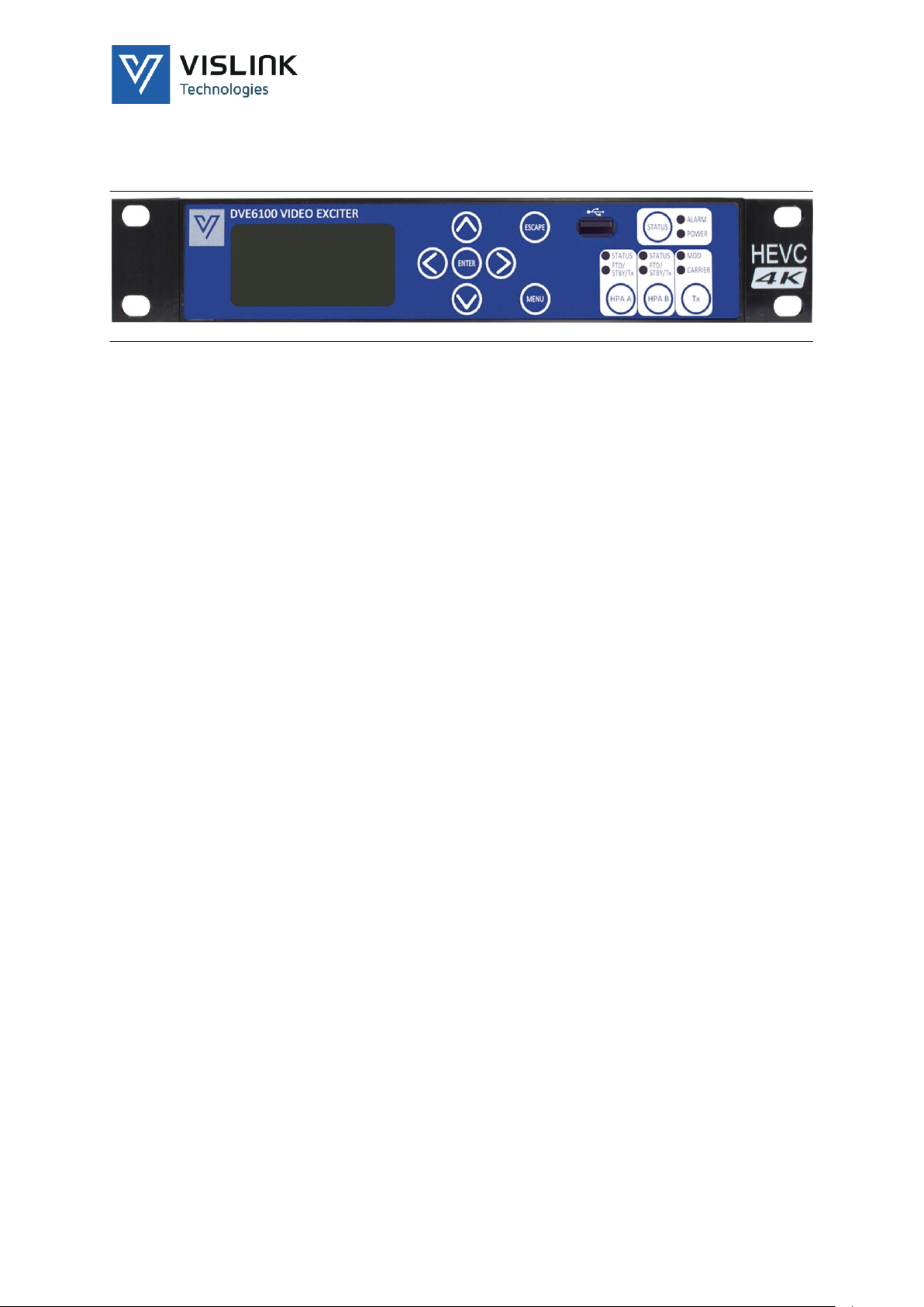
4. Front Panel Overview
4.1. Front Panel
Figure 4-1 DVE6100 Front Panel Overview
4.2. Selection Keys
The <MENU> key provides rapid entry to the main operating menu screen.
Pressing MENU from a main screen returns you to the top of the previous menu
tree.
The <ESCAPE> key acts like the up arrow key when navigating around the
menus. Selecting ESCAPE takes you up a level each press. The ESCAPE button
also exits from an entry operation, aborting changes.
4.3. Menu Scroll Keys
UP / DOWN, LEFT / RIGHT arrow keys select an option displayed in the window
and navigate around the menu tree.
The <ENTER> key initially selects an option or a choice of selection; by using the
UP / DOWN / LEFT / RIGHT arrow keys to change the parameter, pressing
<ENTER> commits the change. Pressing <ESCAPE> aborts the change.
The upper line, in smaller font, of the LCD shows the parameters available by
means of a prompt, access to the next menu level, or a summary of the status of
the menu option.
4.4. Hot Keys
TX key –Used to turn the main output carrier on or off and control the
modulation.
A short press bring up a clean carrier; a further short press turns off the carrier.
Holding the key for 2 seconds brings on the modulation.
A further press will drop the modulated carrier.
STATUS key –Pressing this key brings the user directly to the ALARMS menu
screen.
HPA A (B) key –Future use.

Template Operators Manual
Front Panel Overview
Issue No: 1 Page: 16
Ref: DVE6-ASUM-70xx Copyright © 2019 IMT and Vislink are Vislink Technologies Inc. companies
4.5. LEDs
4.5.1. Alarm
This LED illuminates when an internal error occurs. An amber LED indicates a
minor alarm and a red LED indicates a major alarm.
Program the severity of the alarm indication using the unit webpage.
LED
Function
POWER
When illuminated indicates power is applied to the unit.
MOD
When illuminated green indicates carrier modulation.
CARRIER
When illuminated green indicates the carrier is on.
STATUS (HPA)
If this LED is illuminated green, it indicates the HPA has power
applied and that it is functioning. If illuminated red, this
indicates a fault with the HPA.
FTD / STBY / Tx
When flashing amber, HPA is in filament time delay (FTD)
going into standby when warmed up. If flashing green, HPA is
in filament time delay going into transmit when warmed up.
NOTE: FTD is not valid for SSPAs.
Template Operators Manual
Rear Panel
Issue No: 1 Page: 17
Ref: DVE6-ASUM-70xx Copyright © 2019 IMT and Vislink are Vislink Technologies Inc. companies
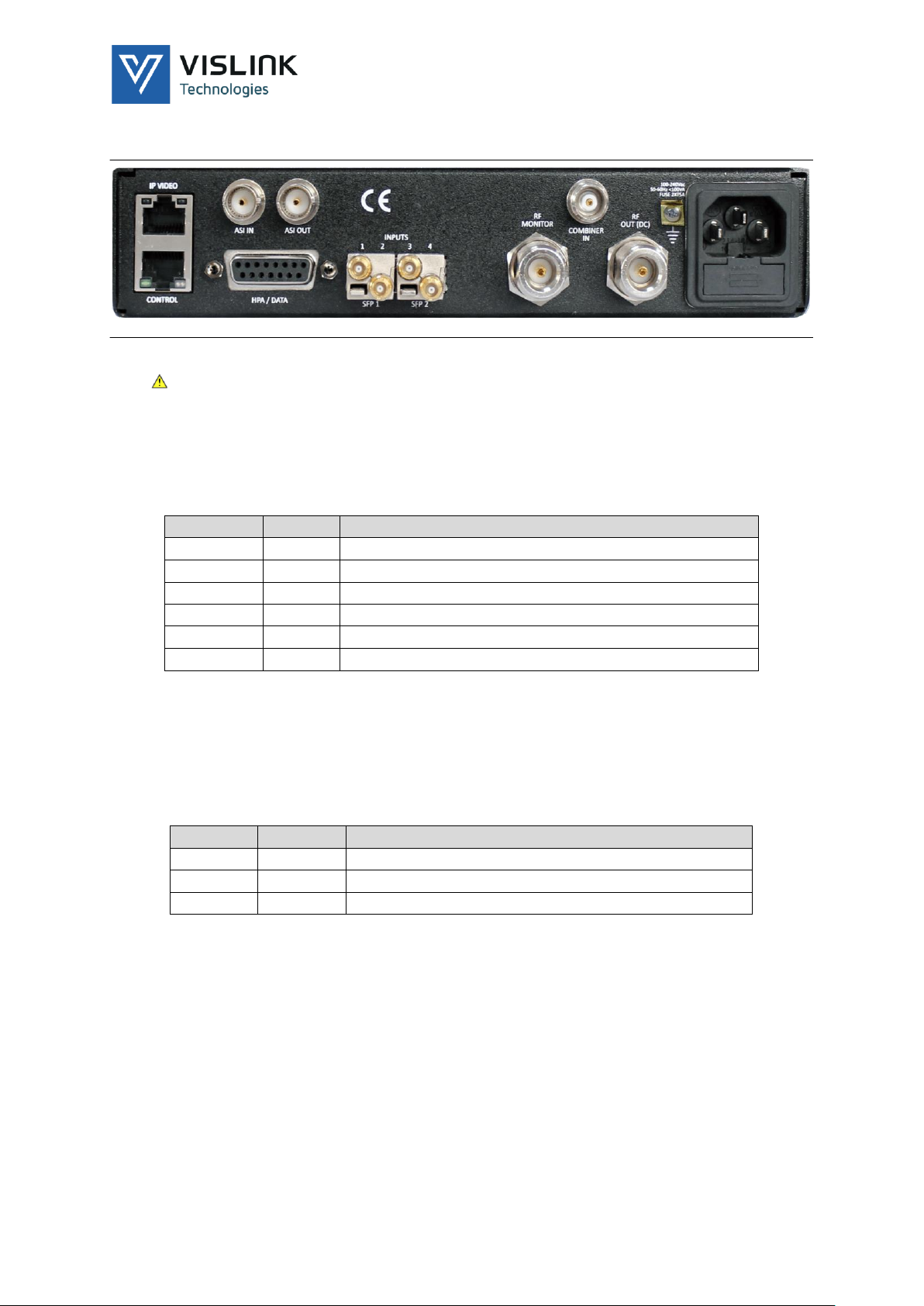
5. Rear Panel
Figure 5-1 Rear Panel Overview
CAUTION: Keep side vents clear at all times. The unit must have adequate
ventilation from the front-left to the rear-right.
5.1. Monitor –Control HPA Control & MPEG Data
The RC&M/HPA/DATA connection is via a female 15-way D connector.
5.1.1. 15-Way D-Type (Female) Pin Definition
15W PIN#
Signal
Description
1
RXA
Remote control RS485 RX+ into DVE /RS232 RX
2
RXB
Remote control RS485 RX- into DVE
3
TXA
Remote control RS485 T+ from DVE
4
TXB
Remote control RS485 TX- from DVE /RS232 TX
7
GND
Ground connection
12
GND
Ground connection
5.2. MPEG User Data
MPEG stream accepts data at 9K6, 19K2 or 38K4 baud.
NOTE: See Section 7.1.6 for more on controlling this data.
The format is in RS232 using the pins defined below.
15W PIN#
Signal
Description
5
Data Rx
RS232 MPEG data input to DVE
6
Data Tx
Not used
7
GND
-
Template Operators Manual
Rear Panel
Issue No: 1 Page: 18
Ref: DVE6-ASUM-70xx Copyright © 2019 IMT and Vislink are Vislink Technologies Inc. companies
5.3. HPA Control
Connect to this 15-way D-type Female, RS485 port to control of a variety of
HPAs or SSPAs.
15W PIN#
Signal
Description
Remark
8
HPA RX -
RS485 RX data - (B) FROM HPA to
DVE
Twisted pair with RX+
9
HPA RX +
RS485 RX data+ (A) FROM HPA to DVE
Twisted pair with RX-
10
HPA TX-
RS485 TX data - (B) TO HPA from DVE
Twisted pair with TX+
11
HPA TX+
RS485 TX data + (A) TO HPA from
DVE
Twisted pair with TX-
12
GND
Ground connection
Overall Screen
5.4. Status Relay
The unit supplies a pair of ground free relay contacts to give a summary alarm
status of the DVE6100 Exciter. The relay default is factory configured for an
open circuit indicating a fail.
To reverse this configuration use the internal status link on the control PCB.
The relay contacts open if the DVE6100 Exciter loses power or has a major
alarm.
15W PIN#
Signal
Description
Remark
14
Status
relay
Relay contact opens on fault
Internal link to swap
NC/NO
15
Status
relay
Relay contact opens on fault
Internal link to swap
NC/NO
5.5. AC Power
The rear panel, 3-pin IEC connector accepts power in the range 90 –264VAC.
The unit employs Live & Neutral conductor fusing.
The two integrated fuses in the IEC connector should be ceramic at T5A rating
each.
The total power consumption is typically less than 70watts.
WARNING: Unplug any external IEC mains leads before removing the lid. The unit
uses dangerous voltages.
CAUTION: Connect a separate EMC earth to the earth point provided.

Template Operators Manual
Rear Panel
Issue No: 1 Page: 19
Ref: DVE6-ASUM-70xx Copyright © 2019 IMT and Vislink are Vislink Technologies Inc. companies
5.6. RF1 Output
The RF1 Output connector is a 50ΩN-type connector that provides the prime RF
output at L-band.
Maximum output is +5dBm.
For systems with high gain, you can configure the maximum output to -5dBm
for a 0dB reading from the front panel.
The control range is 40dB. You may adjust this continuously during transmission.
The recommended system operation level is -10dB, read from the front panel, to
ensure an adequate control range and the best linearity of the system.
You can add a 10MHz precision reference signal to the L-band output, set using
the RF OPTIONS > BUC DC menu. This provides a reference HPAs or SPPAs.
Ensure this option is disabled when not in use.
WARNING: The RF1 connector can have DC present.
5.7. RF2 Output
This 50ΩN-type connector provides an L-band –30dB+/-3dB reduced output,
relative to the L-band at the RF connector.
This monitor connector provides connection to a local IRD or spectrum analyser.
NOTE: No DC or 10MHz reference is present at this connector.
5.8. ASI Input
This 75ΩBNC enables the multiplexing of an external ASI stream with the
internal “service” of the exciter.
The internal service (encoder) may be turned off from the REMUX menu option.
This allows you to use the DVE6100 Exciter as a ‘modulator’, but has a
multiplexer overhead.
For true modulator only mode, purchase a “modulator” licence. This license
reduces the overhead.
See multiplexer option in “Operation Guide” section of this manual.
5.9. Combiner IN
This 50ΩTNC connector provides a 950 - 2150MHz input port. This allows the
internal encoder / modulator / L-band up-converter to combine the signal or
signals.
The combiner is “passive” to prevent corruption of the combined signal should
the DVE6100 Exciter fail.
The combiner has a loss of approximately 6dB. Allow for the loss in the settings
of any external additional carrier(s).
The L-band monitor output comes after the combining process.
No DC or 10MHz pass-through is available on this connector.
NOTE: Terminate the combiner input with 50Ωwhen not in use.

Template Operators Manual
Rear Panel
Issue No: 1 Page: 20
Ref: DVE6-ASUM-70xx Copyright © 2019 IMT and Vislink are Vislink Technologies Inc. companies
5.10. Ethernet/USB Ports
Use the Ethernet port to remote control the DVE6100 Exciter. Access to the
service is via the internal web server using a standard web browser or SNMP.
Use the USB port for licence and software upgrades. License upgrades enable
additional functionality for the DVE6100 Exciter.
Section 8 provides upgrade information and contact details to buy additional
licenses directly from Vislink or from your local representative.
5.11. IP Video (future option)
This Ethernet port is used for “IP encapsulated” ASI transport streams.
The port is compatible with 10/100/1000Base-T Ethernet.
5.11.1. ASI to IP Video
The menu option ASI SRC defines the source of the ASI for encapsulation. This
can be either from, the external ASI connector EXT ASI, the output of the
internal encoder MUX O/P or OFF.
A defined destination address is required to direct Ethernet packets. This is
entered at DEST IP.
As the source of the IP encapsulator could be the output of the internal encoder.
This, in turn, could be a multiplex of several ASI signals. You can stream multiple
ASI channels over one IP path. You can decode separate ASI signals at a remote
location using service names to extract the various services in the same manner
as if it was a direct ASI connection.
Depending on the amount of FEC applied, you can stream approximately 80Mb/s
total over 100M Ethernet.
Encapsulation type ENC TYP the choices are UDP only or RTP/UDP.
You can configure the IP video to cross networks using the default gateway and
sub-net mask setup parameters.
The unit supports Multicast and automatically enables it if the destination
address is set in a multicast address range 224.0.0.0 through 239.255.255.255
inclusive.
5.11.2. IP to ASI
The DVE6100 can de-encapsulate ASI from an incoming RTP IP stream by
selecting the appropriate PORT number.
The external IP source should have its destination address set to that of the
Ethernet PHY of the receiving DVE6100 Exciter; this is set on the IP Ethernet
menu.
IP IN takes the de-encapsulated ASI and multiplexes with the internal encoder(s)
to form a multiservice stream. For multiplexing information, see Section 7.1.5.
You can convert IP Video independently of the encoding functions of the
DVE6100 Exciter. Achieve this by selecting the units ASI output source selection
to be IP.
Table of contents
Other Vislink Media Converter manuals


