Vislink InCam-HS User manual
Vislink, Waterside House, Earls Colne Business Park, Colchester, Essex, CO6 2NS, UK
Telephone: +44 (0)1442 431300 ●Facsimile: +44 (0) 1494 775356 ●Email: sales@vislink.com ●Website: www.vislink.com
Company Registered in England & Wales no. 10523708 ●VAT registration no. GB 260 012 169
Registered Office: Waterside House, Earls Colne Business Park, Colchester, Essex, CO6 2NS, UK
InCam-HS
User Manual

Issue No: 1 Page: ii
Ref:INHS-ASUM-700X Copyright © 2020 IMT and Vislink are Vislink Technologies Inc. companies
Document Disclaimer
The information contained in this manual remains the property of Vislink and
may not be used, disclosed or reproduced in any other form whatsoever without
the prior written permission of Vislink.
Vislink reserves the right to alter the equipment and specification appertaining to
the equipment described in this manual without notification.
This document is supplied on the express terms that it is to be treated as
confidential and that it may not be copied, used or disclosed to others for any
purpose except as authorized by Vislink.
Trademark Information
Add any additional Trademark content from external companies from their
websites trademark pages etc.
Conventions
NOTE: Notes show to convey additional information.
CAUTION: Cautions show where potential equipment damage could occur.
WARNING: Warnings show where there is potential for personal danger or risk of
death. Read all warnings and understand them before carrying out
work on any equipment. This includes peripherals and any related
equipment in use. The danger is real and not reading and
understanding the warning could lead to injury, harm or potential
death.
Service/Support Contacts:
Register for support:
Worldwide: https://support.imt-solutions.com
Call for support:
Worldwide: +44 1442 431410
USA: +1 978 330 9292
When contacting Technical Support, please include the model and serial number
of the unit (located on a label on the bottom of each unit) and the approximate
date of purchase.

Issue No: 1 Page: iii
Ref:INHS-ASUM-700X Copyright © 2020 IMT and Vislink are Vislink Technologies Inc. companies
Document History
Version
Date
Modification
Firmware Version
1
04 AUG 2020
First release of document.
-

Issue No: 1 Page: iv
Ref:INHS-ASUM-700X Copyright © 2020 IMT and Vislink are Vislink Technologies Inc. companies
Table of Contents
1. General Information.............................................................................................. 7
1.1. General Safety Information ..................................................................................................7
1.2. Disposal Instructions...............................................................................................................7
1.3. Environmental .........................................................................................................................7
1.4. Health & Safety .......................................................................................................................8
1.5. Maximum RF Power Density Limits.....................................................................................9
2. InCam-HS Encoder Transmitter Introduction.................................................... 11
2.1. InCam Matrix.........................................................................................................................12
2.2. InCam Optional Items..........................................................................................................12
2.3. Control Panel Operation .....................................................................................................13
2.4. InCam Display .......................................................................................................................13
2.4.1. Main Display..................................................................................................................... 13
2.4.2. Summary Pages .............................................................................................................. 13
3. Specifications....................................................................................................... 15
3.1. Physical...................................................................................................................................15
3.2. Inputs.......................................................................................................................................15
3.3. Output.....................................................................................................................................15
3.4. Video .......................................................................................................................................16
3.5. Audio .......................................................................................................................................16
4. InCam Transmitter Connector Descriptions.................................................... 17
4.1. Camera Connection..............................................................................................................17
4.2. Modulator Input / Output Connectors...............................................................................17
4.2.1. COFDM TX RF................................................................................................................... 17
4.2.2. UHF RX RF....................................................................................................................... 18
4.3. Modulation Options...............................................................................................................18
4.3.1. DVB-T Operation ........................................................................................................... 19
4.3.2. LMS-T Operation............................................................................................................ 19
5. Software Menus................................................................................................... 20
5.1. Icons ........................................................................................................................................20
5.2. SDI Input Type .......................................................................................................................20
5.3. Audio Settings .......................................................................................................................20
5.4. Wi-Fi Settings ........................................................................................................................21
5.5. Recall Default Settings.........................................................................................................21
5.6. Advanced Menu.....................................................................................................................21
5.7. InCam Menus .........................................................................................................................21
6. Mechanics ............................................................................................................. 32
6.1. InCam Docking.......................................................................................................................32
6.2. Battery Plate Docking ..........................................................................................................34
6.3. Docking Modulator module .................................................................................................37
7. InCam Setup ......................................................................................................... 39
7.1. Camera Hardware.................................................................................................................39
7.2. Turning on..............................................................................................................................39
7.3. Video Format Configuration ...............................................................................................40
7.3.1. Video Combinations ..................................................................................................... 40
7.4. Side Panel Indications ..........................................................................................................40

Issue No: 1 Page: v
Ref:INHS-ASUM-700X Copyright © 2020 IMT and Vislink are Vislink Technologies Inc. companies
8. FocalPoint Camera Control................................................................................ 41
8.1. Introduction............................................................................................................................41
8.2. FocalPoint Camera Control Overview...............................................................................41
8.2.1. Menu descriptions ......................................................................................................... 41
9. Firmware Upgrades............................................................................................. 43
Table of Figures
Figure 1-1 Figure 1 Example......................................................... Error! Bookmark not defined.
Table of Tables
Table 1-1 Minimum Safe Distance Overview Table............................................................... 8


Template Operators Manual
General Information
Issue No: 1 Page: 7
Ref:INHS-ASUM-700X Copyright © 2020 IMT and Vislink are Vislink Technologies Inc. companies
1. General Information
1.1. General Safety Information
To ensure awareness of potential hazards, all personnel concerned with the
operation or maintenance of the equipment must study the information that
follows, together with local site regulations.
WARNING: RF Power Hazard: High levels of RF power are present in the unit.
Exposure to RF or microwave power can cause burns and may be
harmful to health. Switch off supplies before removing covers or
disconnecting any RF cables, and before inspecting damaged cables or
antennas.
WARNING: Avoid standing in front of high gain antennas (such as a dish) and
never look into the open end of a waveguide or cable where RF power
may be present.
CAUTION: We strongly recommended that you return any equipment requiring
RF servicing to Vislink.
WARNING- GaAs / BeO Hazard: Certain components inside the equipment
contain Gallium Arsenide and Beryllium Oxide that are toxic
substances. Whilst safe to handle under normal circumstances,
individual components must not be cut, broken apart, incinerated or
chemically processed. In the case of Beryllium Oxide, a white ceramic
material, the principal hazard is from the dust or fumes, which are
carcinogenic if ingested, inhaled or entering damaged skin.
Please consult your local authority before disposing of these components.
CAUTION: Tantalum Capacitors: When subjected to reverse or excess forward
voltage, ripple current or temperature these components may rupture
and could potentially cause personal injury.
CAUTION: This system contains MOS devices. Electro-Static Discharge (ESD)
precautions should be employed to prevent accidental damage.
1.2. Disposal Instructions
WARNING: DO NOT incinerate batteries. Exposing batteries to naked flames or
extreme heat sources can cause them to rupture or explode.
DO NOT dispose of any of the supplied equipment as household waste. The
supplied equipment is not biodegradable in landfill sites. For safe disposal of the
supplied equipment, take it to your local (council/authority) environmental waste
site. For details, contact your local authority/recycling center.
NOTE: In Europe dispose of all equipment in accordance with the European
Environmental directive.
1.3. Environmental
CAUTION: The unit is IPxx rated and must be protected from dripping or
splashing water/fluids. When used outdoors, protect the unit using a
rain cover.
Template Operators Manual
General Information
Issue No: 1 Page: 8
Ref:INHS-ASUM-700X Copyright © 2020 IMT and Vislink are Vislink Technologies Inc. companies
1.4. Health & Safety
Exposure to Non-Ionizing (RF) Radiation/Safe Working Distances
The safe working distance from a transmitting antenna may be calculated from
the relationship:
D =
in which D = safe working distance (meters)
PT = transmitter or combiner power output (watts)
GR = antenna gain ratio = anti log (gain dBi ÷10)
w = Maximum allowed power density (watts/square meter)
The RF power density value is determined by reference to safety guidelines for
exposure of the human body to non-ionizing radiation. It is important to note
that the guidelines adopted differ throughout the world and are from time-to-
time re-issued with revised guidelines. For Vislink use, when calculating
minimum safe working distances, apply a maximum power density limit (w) of
1w/m². Appendix A refers.
WARNING: Any transmitting equipment, radiating power at frequencies of 100
kHz and higher, has the potential to produce thermal and athermal
effects upon the human body.
To be safe:
a. Operators should not stand or walk in front of any antenna, nor should they
allow anyone else to do so.
b. Operators should not operate any RF transmitter or power amplifier with any of
its covers removed, nor should they allow anyone else to do so.
Worked examples:
Antenna
Transmitter Power
Type
Gain (dBi)
Gain Ratio
2W
4W
10W
30W
OMNI
4
2.5
1
1
1.5
2.5
HELIX
20
100
4
5.6
9
15.5
PARABOLIC
DISH
35
3,162
22.5
32
50
87
MINIMUM SAFE DISTANCE (METERS)
Table 1-1 Minimum Safe Distance Overview Table
PT. GR
4.w

Template Operators Manual
General Information
Issue No: 1 Page: 9
Ref:INHS-ASUM-700X Copyright © 2020 IMT and Vislink are Vislink Technologies Inc. companies
1.5. Maximum RF Power Density Limits
The RF Radiation Power Density limit figure recommended by Vislink is based
upon guideline levels published in:
a. IEEE standard C95.1 1999 - IEEE Standard for Safety Levels with respect to
Human Exposure to Radio Frequency Electromagnetic Fields, 3 kHz to 300 GHz.
b. Guidelines for Limiting Exposure to Time-varying Electric, Magnetic &
Electromagnetic Fields (up to 300 GHz) published in 1998 by the Secretariat of
the International Commission on Non-Ionising Radiation Protection (ICNIRP).
Both documents define guideline RF power density limits for "Controlled" and
"Uncontrolled" environments. An uncontrolled environment is defined as one in
which the person subjected to the RF radiation may be unaware of and has no
control over the radiation energy received. The uncontrolled environment
conditions can arise, even in the best regulated operations and for this reason
the limits defined for the uncontrolled environment have been assumed for the
Vislink recommended limit.
Documents a) and b) also show the RF power density guidelines to be frequency
dependent. Different power density / frequency characteristics are presented in
the two documents. To avoid complexity and to avoid areas of uncertainty,
Vislink recommends the use of a single power density limit across the frequency
range 100 kHz to 300 GHz. The 1w/m² power density limit we recommend
satisfies the most stringent of the guidelines published to date.
NOTE: The IICNIRP document is freely available for download from the internet
at www.icnirp.de/emfgdl (PDF file) the IEEE standard is available on loan
from Essex County Library on payment of a search fee.

Template Operators Manual
General Information
Issue No: 1 Page: 10
Ref:INHS-ASUM-700X Copyright © 2020 IMT and Vislink are Vislink Technologies Inc. companies
This page is intentionally unused.

Template Operators Manual
InCam-HS Encoder Transmitter Introduction
Issue No: 1 Page: 11
Ref:INHS-ASUM-700X Copyright © 2020 IMT and Vislink are Vislink Technologies Inc. companies
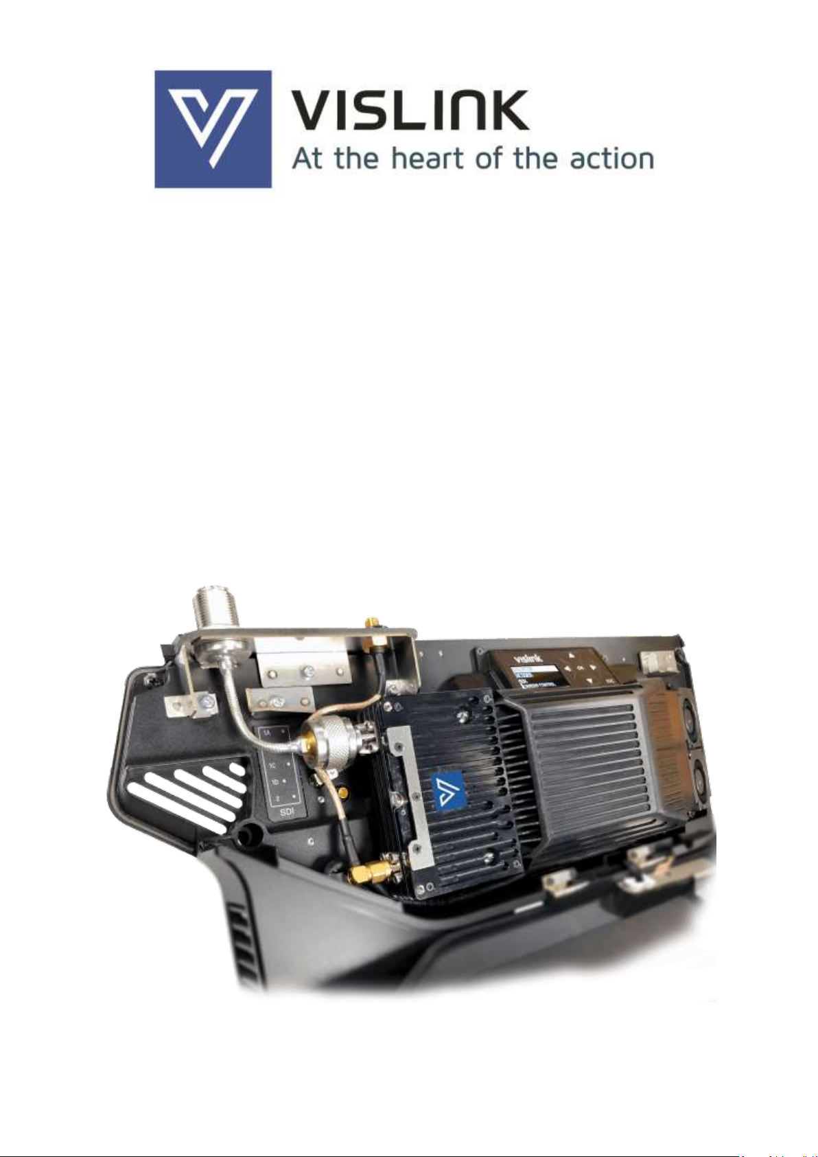
2. InCam-HS Encoder Transmitter Introduction
The Vislink INCAM-HS is a fully integrated HEVC 4K UHD, HDR-ready wireless
system, designed for Sony’s HDC-5500 new 4K multiformat live camera system
using the Sony WKC-WL50 Side panel Adaptor.
The INCAM-HS offers full broadcast quality encoding at 4K UHD, 1080p, 1080i
and 720p with camera control.
The unit utilizes user-changeable RF modules for rapid, in-field, swap outs.
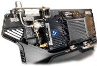
Figure 2-1 Internal Overview
2.1. Internal overview table ID
ID
Description
1
Sony IDX Battery Plate
2
OFDM transmit antenna connector
3
UHF receiver antenna connector
4
Control panel
5
Sony HDC-5500 Camera
6
HEVC encoder
7
Modulator/Up converter module

Template Operators Manual
InCam-HS Encoder Transmitter Introduction
Issue No: 1 Page: 12
Ref:INHS-ASUM-700X Copyright © 2020 IMT and Vislink are Vislink Technologies Inc. companies
2.2.InCam Matrix
The InCam-HS unit comprises of two parts with the main chassis and
interchangeable RF unit, meaning the unit is flexible to changing needs.
Unit Number
O/P
Power
Freq
RF/UHF
Module
Chassis
INHS-ASSY-7001
100/
250mW
1.3-1.7 GHz
HCAM-ASSY-5500
CABK-ASSY-7500
INHS-ASSY-7002
1.95-2.7 GHz
HCAM-ASSY-5501
INHS-ASSY-7003
3.2-3.9 GHz
HCAM-ASSY-5502
INHS-ASSY-7004
100mW
4.4-5.0 GHz
HCAM-ASSY-5503
INHS-ASSY-7005
6.425-7.125 GHz
HCAM-ASSY-5504
INHS-ASSY-7006
6.8-7.5 GHz
HCAM-ASSY-5505
INHS-ASSY-7007
5.4-5.925 GHz
HCAM-ASSY-5506
INHS-ASSY-7008
7.25-7.75 GHz
HCAM-ASSY-5505
2.3.InCam Optional Items
The following table outlines the currently available InCam license and Antenna
options.
INCAM Licenses
HCAM-LICE-0001
HCAM/INCAM LICENSE SERVICE 1 4K UHD ENCODE + HD 1080P
HCAM-LICE-0007
HCAM/INCAM LICENSE H.264 ENCODING
HCAM-LICE-0008
HCAM/INCAM LICENSE DEEP INTERLEAVING
HCAM-LICE-0009
HCAM/INCAM LICENSE VARIABLE BANDWIDTH LMS-T
HCAM-LICE-0010
HCAM/INCAM LICENSE UHF RX CAMERA CONTROL
HCAM-LICE-0011
HCAM/INCAM LICENSE BISS SCRAMBLING
Antenna Options
L0018-4145
ANTENNA UHF 410-450MHz SMA(M) RED CAP
L0018-4549
ANTENNA UHF 450-490MHz SMA(M) BLUE CAP
Template Operators Manual
InCam-HS Encoder Transmitter Introduction
Issue No: 1 Page: 13
Ref:INHS-ASUM-700X Copyright © 2020 IMT and Vislink are Vislink Technologies Inc. companies
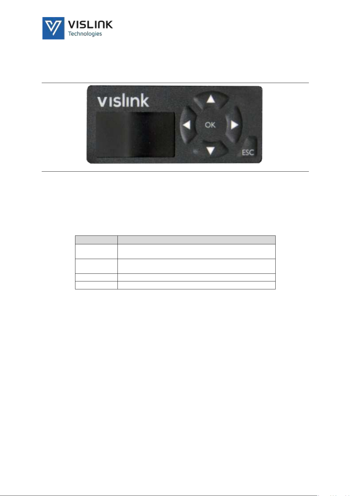
2.4.Control Panel Operation
Use the InCam control panel to configure and make in-field changes to the unit’s
configuration.
Figure 2-2 Control Panel
Use the directional pads to navigate through the menu structure, displayed on
the OLED screen.
Press OK to accept and save changes.
Press ESC to cancel, exit and back out of menus.
Action
Function
Up and
down
Modifies alphanumeric values
Left and
right
Changes the alphanumeric character being edited /
Navigates
OK
Accepts the newly edited value (or enters menus)
ESC
Cancels the edit (or exits menus)
When you power on the INCAM, it reverts to the last known condition.
2.5.InCam Display
2.5.1. Main Display
The InCam encoder has an integrated OLED display. The brightness of OLED
displays reduces with usage. To increase the life of the OLED display, we advise
that you enable the display time-out where possible. Operating the directional
keys reactivates the display after a time-out. The default for the timeout comes
enabled and set to 30 seconds.
2.5.2. Summary Pages
The InCam display provides a tree like menu structure of control parameters and
status indicators. In addition, at the top level of the menu structure, there are
summary pages, accessed using the Esc keypad. The summary pages, along with
the display icons, give quick access to important parameters. Press OK to access
menus.

Template Operators Manual
InCam-HS Encoder Transmitter Introduction
Issue No: 1 Page: 14
Ref:INHS-ASUM-700X Copyright © 2020 IMT and Vislink are Vislink Technologies Inc. companies
Template Operators Manual
Specifications
Issue No: 1 Page: 15
Ref:INHS-ASUM-700X Copyright © 2020 IMT and Vislink are Vislink Technologies Inc. companies
3. Specifications
3.1. Physical
Feature
Description
Dimensions
245 x 38 x 115 mm
Weight
688g
Temperature
-20oC to 45oC (-4oF to 113oF)
Power Connector
4-pin MOLEX
Power Consumption
Nominally 30W in standard configuration
(with 1.95-2.7 GHz)
3.2.Inputs
Feature
Description
Audio
Embedded audio over SDI/HD-
SDI/3G from camera
UHF Receiver
410 to 490MHz range
FocalPoint camera control
compatibility
3.3.Output
Feature
Description
Frequency Band
See the InCam Matrix table.
Transmit Power
10 to 250mW (or add barrel booster option)
Transmit Antenna
Omni-directional 3 dBi gain (nominal)
Frequency Selection
Up to 32 preset channels for tuning
Modulation
COFDM DVB-T or LMS-T
Modulation Modes
DVB-T:
-QPSK, 16QAM, 64QAM
-FEC: 1/2, 2/3, 3/4, 5/6, 7/8
-Guard Interval: 1/32, 1/16, 1/8, 1/4
LMS-T:
-QPSK, 16QAM
-FEC: 1/2, 2/3, 3/4, 5/6, 7/8, 9/10, 14/15
-Guard Interval: 1/16, 1/8
Data Rate
DVB-T 4.98 to 31.7 Mbit/s
LMS-T up to 43 Mbit/s bandwidth dependent
(licensed option)
Bandwidth
DVB-T: 6/7/8MHz
LMS-T: 3/4/5/6/7/8/10/12/14/16/20MHz or
24MHz with two carrier density options
Optional pre-distortion for enhanced adjacent
channel performance (frequency permitting)

Template Operators Manual
Specifications
Issue No: 1 Page: 16
Ref:INHS-ASUM-700X Copyright © 2020 IMT and Vislink are Vislink Technologies Inc. companies
3.4.Video
Feature
Description
Video Formats
480i/29.97
576i/25
720p/50, 59.94, 60
1080i/50, 59.94, 60
1080p/23.98, 24, 25, 29.97, 30, 50, 59.94, 60
2160p/23.98, 24, 25, 29.97, 30, 50, 59.94, 60
Video Encoder Profiles
H.265 HEVC Main, Main-10:
- H.265 HEVC 8/10 Bit to 4K 60p
H.264 AVC Main, High, Baseline up to Level 5.2:
- H.264 AVC High 10/4:2:2
- H.264 AVC 4:2:0/4:2:2
- 8/10 Bit to HD 60p
4K Native and UHD (1 Service)
- 4.2.0 Main
- 4.2.2 Main
Encoding
HEVC (H.265)
AVC (H.264)
MPEG-2 (H.262)
3.5.Audio
Feature
Description
Encoding
AAC
MPEG-1
AES/Dolby Pass through

Template Operators Manual
InCam Transmitter Connector Descriptions
Issue No: 1 Page: 17
Ref:INHS-ASUM-700X Copyright © 2020 IMT and Vislink are Vislink Technologies Inc. companies
4. InCam Transmitter Connector Descriptions
The InCam Side Panel unit consists of two assemblies. The main chassis housing
encoder hardware and the interchangeable transmitter module.
4.1. Camera Connection
Figure 4-1 Camera Connection
Feature
Description
1.
Multiway camera connection
2.
Molex power connection
4.2.Modulator Input / Output Connectors
4.2.1. COFDM TX RF
100mW into 50Ω–switchable. 10, 50, 100 and 250mW fixed power settings,
and a user-adjustable mode between zero and 24dBm.
NOTE: 250mW is for use in FCC regulatory regions only.
50Ωchassis mounted ‘N’type bulkhead socket.
Antenna:
L3421 TX Omni Spring 3 dBi 1.95-2.7GHZ
L3423 TX Omni Spring 3 dBi 1.95-2.7GHZ (Extra Long)
L3424 TX Omni Spring 3 dBi 3.0-3.7GHZ

Template Operators Manual
InCam Transmitter Connector Descriptions
Issue No: 1 Page: 18
Ref:INHS-ASUM-700X Copyright © 2020 IMT and Vislink are Vislink Technologies Inc. companies
WARNING: There should always be an antenna connected to the N-type
connector when the unit is powered.
4.2.2. UHF RX RF
SMA connector for UHF receive antenna: 410-490MHz.
Antenna: L0018-4145 410-450MHz SMA (M) Red Cap
Antenna: L0018-4549 450-490MHz SMA (M) Blue Cap
4.3.Modulation Options
The modulator operates as one of three main types:
1. Single Pedestal LMST(S)
2. Dual Pedestal LMST(D)
3. DVB-T
Modulation options are selected in the MODULATOR > Modulation menu. Here,
you select either LMST or DVB-T.
Select the Bandwidth from MODULATOR > Bandwidth menu.
NOTE: In LMST(D) mode, the bandwidth shown is the combined width of the two
pedestals.
The LMST bandwidths:
•Single Pedestal:
−3, 4, 5, 6, 7, 8, 10, 12 MHz
NOTE: Without a variable bandwidth license, only 10MHz is available.
•Dual Pedestal:
−6, 8, 10, 12, 14, 16, 20 & 24 MHz
NOTE: Without a variable bandwidth license, only 20MHz is available.
The DVB-T bandwidths:
•6, 7 & 8 MHz

Template Operators Manual
InCam Transmitter Connector Descriptions
Issue No: 1 Page: 19
Ref:INHS-ASUM-700X Copyright © 2020 IMT and Vislink are Vislink Technologies Inc. companies
4.3.1. DVB-T Operation
The table below defines the corresponding gross bit rates for DVB-T operation.
This includes video, audio, data and other transport stream data tables.
Bitrates (Mbit/s) for a DVB-T system in 8 MHz channels
Modulation
Code Rate
Guard Interval
1/4
1/8
1/16
1/32
QPSK
1/2
4.976
5.529
5.855
6.032
2/3
6.635
7.373
7.806
8.043
3/4
7.465
8.294
8.782
9.048
5/6
8.294
9.216
9.758
10.053
7/8
8.709
9.676
10.246
10.556
16-QAM
1/2
9.953
11.059
11.709
12.064
2/3
13.271
14.745
15.612
16.086
3/4
14.929
16.588
17.564
18.096
5/6
16.588
18.431
19.516
20.107
7/8
17.418
19.353
20.491
21.112
64-QAM
1/2
14.929
16.588
17.564
18.096
2/3
19.906
22.118
23.419
24.128
3/4
22.394
24.882
26.346
27.144
5/6
24.882
27.647
29.273
30.16
7/8
26.126
29.029
30.737
31.668
4.3.2. LMS-T Operation
The table below defines the corresponding gross bit rates for LMS-T operation at
the most common bandwidths (Single or Dual pedestal):
Bitrates (Mbit/s) for a LMS-T system
Channels
Guard Interval
Modulation
Code Rate
10MHz
20MHz
24 MHz
1/8
1/16
1/8
1/16
1/8
1/16
QPSK
2/3
9.2
9.7
18.4
19.5
22.1
23.4
16QAM
2/3
18.4
19.5
36.8
39
44.2
46.8

Template Operators Manual
Software Menus
Issue No: 1 Page: 20
Ref:INHS-ASUM-700X Copyright © 2020 IMT and Vislink are Vislink Technologies Inc. companies
5. Software Menus
5.1. Icons
Icon
Condition
Format
Tx Icon
RF on
(Animated antenna icon)
RF off
(Antenna icon with cross)
Video Icon
Video input locked
(Quadrant solid white)
Video not locked
(Quadrant flashes)
Video input not selected
(Quadrant blank)
All Video inputs not selected
(Screen out icon)
Alarm
indicates a system error or warning
NOTE: The Video locked icon shows any active screens shaded in white.
5.2.SDI Input Type
The InCam accepts both Level-A and Level B 3G-SDI streams. When using UHD
or 4K video formats, the video carries over a quad link SDI interface.
-
Quad Link
SMPTE ST-
UHDp60
4x 3G-SDI
425-5
UHDp59
4x 3G-SDI
425-5
UHDp50
4x 3G-SDI
425-5
UHDp30
4x HD-SDI
425-3
UHDp29
4x HD-SDI
425-3
UHDp25
4x HD-SDI
425-3
UHDp24
4x HD-SDI
425-3
UHDp23
4x HD-SDI
425-3
5.3.Audio Settings
The InCam supports up to eight AAC or four MPEG compressed audio pairs at
various bit rates from 32kbps up to 576kbps. It also supports four uncompressed
PCM or Dolby-E pass-through pairs.
Table of contents
Other Vislink Media Converter manuals


