Uni-Com GEP-5400TF-C User manual

908 Canada C urt
City f Industry, CA 91748 U.S.A.
Phone: 626.964.7873 r 800.346.6668 Fax: 626.964.7880
www.unic mlink.c m e-mail: inf @unic mlink.c m
©UNICOM 2009. UNICOM and “A Network Syste s Solution” are trade arks of UNICOM Electric, Inc.
All rights reserved. Specifications subject to change without notice.
Rev: 06.09
USER’S MANUAL
10/100/1000Base-T
1000Base-SX/LX
Gigabit Ethernet Converter
For full coverage of your warranty, be sure
to register your product using the enclosed
registration card.
GEP-5300TF-C 1000Base-T/SX (SC/MM/550 )
GEP-5400TF-C 1000Base-T/LX (SC/SM/10k )
Rev. 2.0

Package Con en s
Package contents include the following:
1 10
IMPORTANT: If any piece is missing or damaged, please contact your
local dealer or reseller for service.
For Your Records
Product Name:
Serial Number:
Date of Purchase:
Purchased from:
Notes:
Gigabit User’s Ma ual Power Adapter Rack Mou t
Co verter Brackets
(Multi-Mode or Single Mode)
■10/100/1000Base-T to 1000Base-SX/LX Converter
(Multi-Mode or Single Mode)
■DC Power Adapter
■User’s Manual
■Rack Mount Brackets
■Warranty card (not shown)

In roduc ion
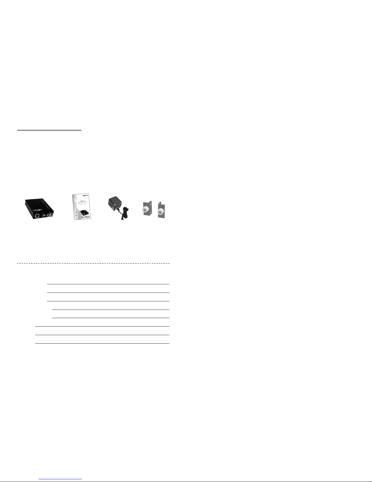
Congratulations on purchasing a quality UNICOM product.
Unicom’s VELOCITY Series represents the newest, most advanced
generation of signal conversion technology.
Unicom’s Giga Fiber Converter is a cost- effective solution for the
conversion of 10/100/1000Base-T (Auto MDI/MDIX) and pure 1000
Base-T to 1000Base-SX/LX cabling. It can be slotted into a multi-
converter chassis that enhances your network flexibility. It can also be
used as a stand-alone converter.
The Giga Fiber Converter will allow you to extend the cabling distance of
your 10/100/1000Base-T (Auto MDI/MDIX) or pure 1000 Base-T
network up to 550m for multi-mode fiber or 10 kilometers for single-
mode fiber. This Converter uses the most popular fiber cabling
connectors: SC multi- mode fiber connector and SC single-mode fiber
connector.
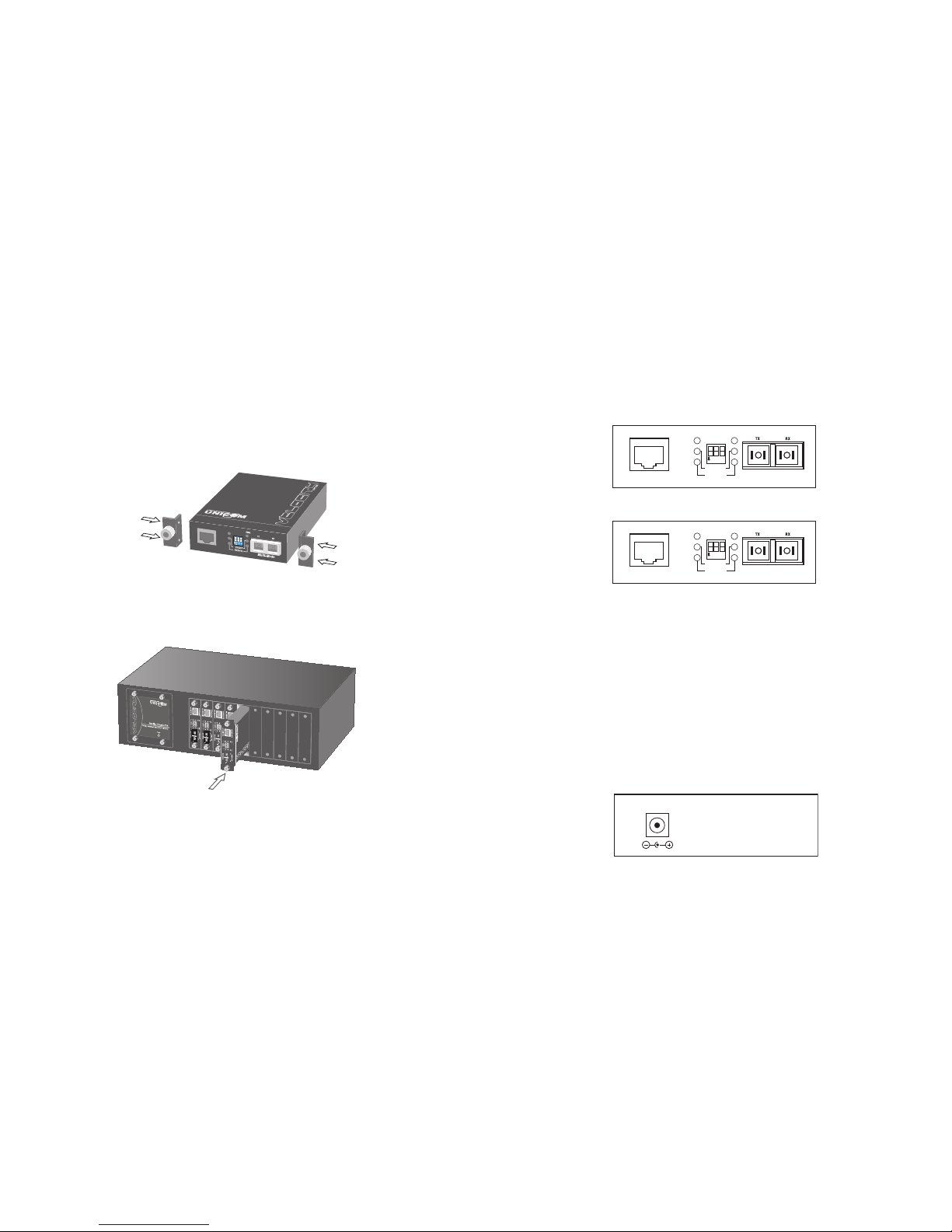
The Modular Giga Fiber Converters provides one Fiber connector for fiber
optic cable and one Ethernet RJ-45 port (Auto MDI/MDIX) for
10/100/1000Base-T copper cable or pure 1000 Base-T copper cable
connections. There are DIP- switches to set the operation mode for UTP,
Fiber ports and link lost forwarding function.
Produc Specifica ions
Standard Compliance: IEEE 802.3 10/100/1000Base-T Gigabit Ethernet
IEEE 802.3 1000Base-SX/LX Gigabit Ethernet
Protocol: CSMA/CD
Interface: (1) 10/100/1000Base-T, Shielded RJ-45 Jack
(1) 1000Base-SX/LX, Dual SC connector
Cable distance: 10/100/1000Base-T
Cat. 5e or 6: up to 100m.
1000Base-SX: Multi-mode iber
50/125µm (550m)
62.5/125µm (550m)
1000Base-LX: Single Mode iber
9/125µm (10Km)
LED Indicators: Power, Speed, Link/Activity (copper and iber),
Full-Duplex (copper), Full-Duplex/collision ( iber)
Power Supply: External power adapter 9V DC/700mA (min.)
Operating Temperature:
0˚C to 45˚C
Operating Humidity: 10% - 90% RH
EMI: FCC Class A, CE Mark
Enclosure: Metal
Dimensions: 120mm x 85mm x 26mm (L x W x H)
Warranty: Limited Li etime
FCC Statement
This equipment has been tested and found to comply with the limits for a class B device, pursuant
to part 15 of the FCC rules. These limits are designed to provide reasonable protection against
harmful inter ference in a commercial installation. This equipment generates, uses and can
radiate radio frequency energy and, if not installed and used in accordance with instructions, may
cause harmful inter ference with radio communications. Operation of this equipment in a
residential area is likely to cause harmful inter ference, in which case, the user will be required to
correct the interference at the user’s expense.
9 2

3 8
Cabling
• Twisted-pair segments can be Unshielded Twisted Pair (UTP) or
Shielded Twisted Pair (STP) cabling. The cable must comply with the
IEEE 02.3 10/100/1000Base-T standard for Category 5e/6. The
cable between the converter and the link partner (switch, hub,
workstation, etc.) must be 100 meters (32 ft.) or less in length.
• Fiber segments using Si gle Mode connectors must use 9/125µm
Single Mode fiber cable. The maximum link distance in full duplex
operation is 10 Kilometers (6.2 miles). The maximum link distance
in half duplex operation is 412 meters (1352 ft).
• The maximum distance of fiber segments using Multi-Mode
connectors measures 550 meters (1 04 ft.) with 50/125µm or
62.5/125µm Multi-Mode fiber cable.
Ne work Connec ion
A. Select the appropriate length Category 5e or 6 twisted pair cable.
Connect one end of the twisted pair cable to the RJ-45 connector
on the converter and the other end of twisted pair cable to the RJ-
45 connector on any 10/100/1000Base-T device.
B. Connect one end of a fiber jumper to the SC connector on this
converter and the other end of the fiber jumper to the SC
connector on the other 1000Base-SX/LX device.
C. Attach the power adapter DC jack to the converter. Verify that the
Power LED is on.
D. Verify that the UTP “LK/ACT” LEDs light when cable connection is
installed correctly. Verify that Fiber “LK/ACT” LED blinks to indicate
network activity.
Troubleshoo ing
• Verify that you are using the right power adapter, DC 5V, 2A
(minimum). Using a power adapter with DC output greater than 5V
could result in damage to the unit and/or personal injury.
• Confirm the proper UTP/Fiber cable is being used. The Single Mode
converter must use Single Mode fiber optic cable.
Key Fea ures
Sta dards: IEEE 02.3 10BASE-T
IEEE 02.3u 100BASE-TX
IEEE 02.3ab 1000BaseT,
IEEE 02.3z 1000BaseSX/LX standards
IEEE 02.3x Flow Control and Back pressure
LED I dicators:
Power (Green)
UTP SPD: 1000Mbps /100Mbps / 10Mbps
Lnk/Act: UTP /FIBER
FDX: UTP: Full-Duplex mode / Half-Duplex or Link down
FIBER: Full-Duplex mode / Link down
Co ector: Fiber: Duplex SC
RJ-45 Socket: CAT-5e (10/100/1000Mbps) Twisted Pair
cable Auto MDI/MDI-X and Auto-Negotiation Function
Support
Fiber parameters:
Fiber Core: Multi-Mode (62.5/125um, 50/125um)
Single-Mode (9/125um)
Wavelength: 50nm(Multi-mode),
1310nm(Single-mode)
Fiber Distance: 550m (Multi-Mode Fiber)
10km (Single-Mode Fiber)
Li k Loss Forward:
Copper to Fiber: If copper port link down, then media
converter will forced fiber to link down.
Fiber to Copper: If Fiber port link down, the media
converter will forced copper port to link down.

Ins alling Conver ers in o Chassis
Follow the steps below to install modular converters into the 10 space
Converter Chassis (pn: FEP-593110).
A. Remove the blank bracket from the chassis by rotating screw
counterclockwise. Put the blank bracket aside.
B. Open the rack mount bracket kit. The kit contains two rack mount
brackets and four screws.
C. Use a screwdriver to attach the rack mount ears to both sides of
the modular converter.
D. Install the modular converter by inserting it into the chassis
guides and sliding it in until it stops. Press it firmly to seat the
chassis power plug into the modular converter receptacle.
E. Gently push the thumbscrews in and turn clockwise to tighten.
Do not over tighten.
7 4
Hardware Descrip ion
The Fron Panel
The Front Panel of the 10/100/1000T to 1000SX/LX converters
consists of one RJ-45 Port ( Auto MDI/MDIX ) one fiber 1000Base-
SX/LX Port and 6 LED Indicators (SPD, LK/ACT, FDX, Fiber LK/ACT,
FDX/COL and PWR ).
Por s
•Copper Port: RJ-45 Port (Auto MDI/MDIX), the Ethernet RJ-45 will
features Auto-Sensing for 10/100/1000Base-T connections and
Auto MDI/MDIX which is basically an auto crossover feature. This
means you can connect to another Switch or workstation without
changing to a crossover cable.
•Fiber Port: This port is for the 1000Base-SX/LX connection and is
available in the SC format in Multi- and Single mode.This fiber por t
does not support auto-negotiation.
The Rear Panel
The rear panel contains a power socket. This power socket accepts
DC9V voltage and minimum 0.7A supplied current.
Multi-ModeAuto MDI/MDIX
10/100/1000T 100Base-SX
LK/ACT
FDX/COL
SPDPWR
1 2 3
ON
Single ModeAuto MDI/MDIX
10/100/1000T 1000Base-LX
LK/ACT
FDX/COL
SPDPWR
12 3
ON
GEP-5300TF-C 550
GEP-5400TF-C 10k
DC IN
Auto MDI/MDIX
10/100/1000T100Base-SX
SPD

DIP Swi ch Descrip ion
The DIP-switch is used to configure operation mode for LLF (Link
Lost Forwarding) and operation mode for Copper/Fiber port. The
default value of Dipswitch is OFF.
10/100/1000Base-T to 1000Base-FX co verter module
Li k Lost Forwardi g: When LLF is enabled, it will allow copper port
link failure to be repor ted to the Fiber side and will also allow Fiber
link failure to be repor ted to the copper side. Therefore, a link loss
forward feature is provided on both copper and Fiber sides.
Pure Co verter mode: When Pure Converter mode is enabled (ON),
the switch operates with the minimum latency. The transmission flow
does not wait until an entire frame is ready but instead for wards the
received data immediately after being received. The TP should be
forced at 1000M in this application.
When the DIP-Switch is in Switch Converter mode (OFF), the
converter function is the same as a Switch Hub.
[Note]
1) Do not change the DIP-switch setting when the copper or fiber port is
transmitting or receiving data. It may cause data error.
2) Power off, then power on when changing the DIP-switch setting.
LED Indica ors
There are six diagnostic LEDs located on the front panel of these
converters. The LEDs provide real-time information on system status.
The indicators include SPD, LK/ACT, FDX, Fiber LK/ACT, FDX/COL and
PWR. The following table provides describes these LEDs:
5 6
No. Status Description
1 Off LLF enabled
On LLF disabled
2 Off Switch Coverter Mode
On Pure Converter Mode
3 Off Reserved
On Reserved
LED Status Color Descriptio
PWR On Green • The converter is supplied with
suitable power.
SPD On Green • Current UTP Speed is 1000Mbps
( speed ) On Amber • Current UTP Speed is 100Mbps
Off -• Current UTP Speed is 10Mbps
LK/ACT On Green • Unit is connected with a link
( UTP ) Blinking -•Unit is transmitting data
Off -•No device attached
FDX ( UTP ) On Orange • The UTP port is in full-duplex mode.
Off -•Half-duplex mode/no device attached
LK/ACT On Green • Unit is connected with a link
( Fiber ) Blinking -•Unit is transmitting data
Off -•No device attached
FDX/COL On Amber • The UTP port is in full-duplex mode
( Fiber ) Off -•No device attached
This manual suits for next models
1
Table of contents
Other Uni-Com Media Converter manuals
Popular Media Converter manuals by other brands

turck
turck RI QR20 Series Instructions for use

Calpeda
Calpeda VARIOMAT 2 Series Original operating instructions

MG
MG WRPPB instruction manual

Vega Absolute
Vega Absolute TP-11 user manual

Rose electronics
Rose electronics CNV-DVIVGA Series Quick installation guide

IMC Networks
IMC Networks MediaConverter 1 Operation manual