Instructions
Nomenclature
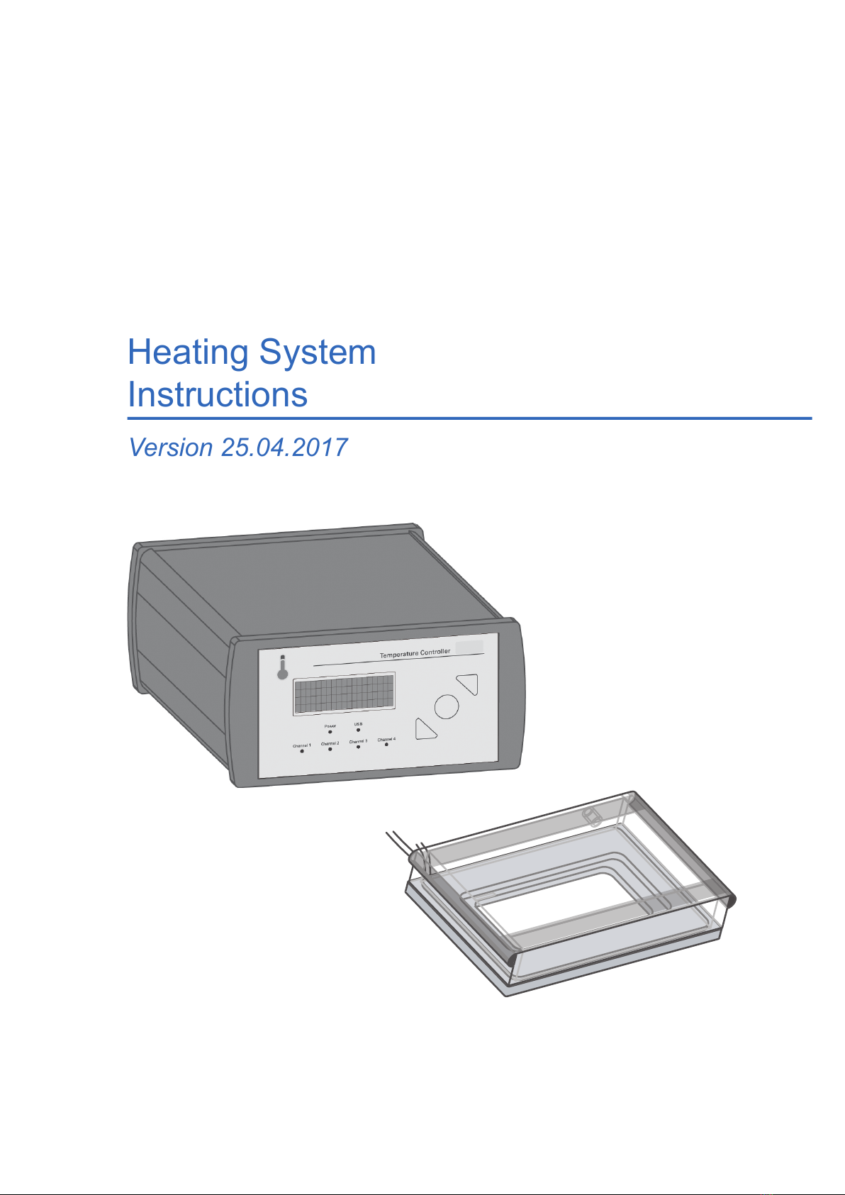
Temperature Controller
Heated Lid
Heated Plate
WARNING!
• Do only operate the Heating Devices with the supplied Temperature Controller.
• Do only use the delivered cables and plugs. If not doing so you risk electric shock and fire.
• Do not operate the Heating System with substances or under conditions, that can cause a risk
of explosion, implosion or the release of gases.
CAUTION
• Ensure that the external power supply is well accessible. The Heating System must be installed
in such manner that none of its components hinders access to the external power supply.
• The weight of the Temperature Controller is approx. 3 kg. Moving the Temperature Controller
during operation will pose a risk of personal injury or damage to the instrument.
• Some accessible parts of the Heated Plate and Heated Lid can reach temperatures up to 55°C.
Avoid touching the temperature-controlled parts of the system when you have set the Temper-
ature Controller to high temperatures.
• The glass plate of the Heated Lid can break due to a mechanical impact. If so, the shards can
lead to injuries if handled.
• Be aware that when the system is switched on, 10 V AC voltage is applied to the underside of
the glass on the Heated Lid and bottom of the Heated Plate. Do not touch the underside or put
it in contact with anything conductive. This could cause a short circuit that may destroy the
Temperature Controller and/or the Heating Devices.
• Only use the Heating System in dry rooms.
• Do not use the Heating System in cold rooms.
• Use the Heating System only for cell experiments with aqueous solutions.
• Do not use the Heating System with hazardous substances or substances/materials that pose a
risk of infections.
• Do not use extension cords. Immediately replace damaged cords, plugs, or cables to avoid a
risk of personal injury or damage to the instrument.
• Only ibidi technical staff is permitted to open and service the Heating Devices and/or Temper-
ature Controller.
• Unplug the external power supply when the Heating System is not in use.
Version (26th April 2017) Heating System 5