________________________________________________________________________________
VAISALA ________________________________________________________________________ 5
CHAPTER 8
REPAIR ........................................................................................................ 91
Replacing Window Assembly CLW311 ................................ 91
Replacing Ceilometer Laser Transmitter CLT311............... 93
Replacing Ceilometer Receiver CLR311.............................. 94
Replacing Ceilometer Engine Board CLE311.................... 100
Replacing No-break Battery 4592 ....................................... 101
Replacing AC Power CLP311.............................................. 102
Replacing Window Blower CLB311-115 / CLB 311-230.... 104
Replacing Ceilometer Optics CLO311................................ 105
Replacing Internal Heater CLH311-115 / CLH311-230 ...... 107
Replacing Internal Cable Set............................................... 109
Replacing Laser Monitor Board CLM311........................... 113
Replacing Modem Module DMX501 (Optional).................. 115
CHAPTER 9
TECHNICAL DATA .................................................................................... 117
Specifications ....................................................................... 117
Mechanical Specifications................................................. 117
External Connector J1 - Window Conditioner ................... 118
External Connector J2 - Power Input ................................ 118
Output Interface ................................................................ 118
External Connector J3 - Data Line............................... 119
External Connector J4 - Maintenance Line.................. 120
Modem Module DMX501 .................................................. 121
Transmitter Specifications................................................. 121
Receiver Specifications..................................................... 122
Optical System Specifications........................................... 122
Performance Specifications .............................................. 122
Environmental Conditions Specifications.......................... 123
INDEX ......................................................................................................... 125
List of Figures
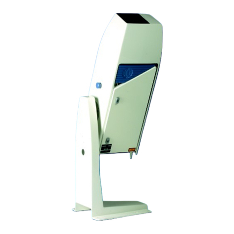
Figure 1 Vaisala Ceilometer CL31.......................................................... 14
Figure 2 Ceilometer CL31 Main Parts .................................................... 16
Figure 3 Measurement Unit Handle ....................................................... 20
Figure 4 Foundation Construction .......................................................... 21
Figure 5 Removing and Attaching the Measurement Unit ..................... 23
Figure 6 Mounting the Shield.................................................................. 24
Figure 7 External Connectors (Bottom View) ......................................... 25
Figure 8 Data Line Modem Connection.................................................. 26
Figure 9 Data Line RS-485 Connection ................................................. 27
Figure 10 Data Line RS-232 Connection ................................................. 28
Figure 11 Subassembly Interconnections ................................................ 32
Figure 12 CL31 Switches ......................................................................... 33
Figure 13 Ceilometer Engine Board CLE311 ........................................... 34
Figure 14 Operation Modes...................................................................... 37
Figure 15 Open and Closed Port.............................................................. 39
Figure 16 Typical Measurement Signal.................................................... 74


