Single-phase meter 100A with port RS-485
Single-phase multitariff meter 100A with port RS-485
ORNO-LOGISTIC Sp. z o.o.
ul. Katowicka 134
43-190 Mikołów
tel. 32 43 43 110
Service and assembly manual
IMPORTANT!
Before use of the device, read this service manual and keep it for future. Repairs and modifications carried out by yourselves result in the
guarantee invalidation. The manufacturer is not liable for damages that can get out of improper device installation or operation.
In view of the fact the technical data are subject to continuous modifications, the Manufacturer reserves the right to make changes in the
product characteristics and to introduce another constructional solutions that do not deteriorate the product parameters and use values.
The latest version of themanual can bedownloaded from www.orno.pl. Any rights to translate /construe and thecopyright of this manual are
reserved.
The meter should be installed by a qualified personnel - persons having knowledge on marking and grounding the electrical appliances and
knowing regulations concerning safety. Improper installation can make a risk of electric shock or fire. Do not use the device contrary to its
intended use.
The meter shall be stored in a dry room.
Do not immerse the device in water or another fluids.
Do not install nor operate the device with damaged housing.
Do not modify the device nor repair it by yourselves.
Use only insulated tools.
To avoid electric shock or meter damage, switch off the supply voltage before any change of the connection system.
Before connection of the supply voltage, make sure that all conductors are connected properly.
The meter is designed for installation in mechanical environment "M1” where shocks and vibrations are insignificant according to the
directive 2014/32/EU. The meter is designed for installation in electromagnetic environment "E2” according to the directive 2014/32/EU.
NOTE: The 24-months’ guarantee includes the product equipped with the factory seal that must not be broken!
Any household is a user of electric and electronic equipment and therefore a potential producer of waste, hazardous for people and environment due to presence of hazardous substances, mixtures and
components in the equipment On the other hand, the used equipment is a valuable material due to such a raw material as copper, tin, glass, iron, etc. to be recovered.
The symbol of the crossed litter bin placed on the equipment, a package or accompanying documents means that the productmust not be discarded together with other wastes. The marking means also that
the equipment was introduced for trade after 13th August 2005. The useris obliged to transfer the used equipment to an appointed collection point forits proper processing. Information on an available system
of used electronic equipment collection can be found at the shop information desk and at the municipality / commune office.
Proper disposal of used equipment prevents negative consequences for the natural environment and human health!
1. INTRODUCTION
OR-WE-512, OR-WE-514, OR-WE-515 are the single-phase, single-modulemeters with the backlit LCD, to be mounted on the DIN rail. They are used to
monitor consumption of electric energy from the single-phase network. They are ideal devices to be used as submeters of alternating current. They are
only 18 mm wide but they correspond to the communication standard RS485 and meet the standard DIN EN 50022 that is proper for the current
distribution system at household and commercial uses.
2. PROPERTIES AND TECHNICAL PARAMETERS
2.1 Properties
The meter can read network parameters, analyse energy quality and load condition at certain period.
To be mounted on the standard DIN rail - the width is only 18 mm.
OR-WE-514 Themeter can register the electric energy consumed, with possibility of remote readout of the index group register through the wire network
of the standard RS485, protocol: Mode Modbus-RTU.
OR-WE-515 Themeter can register the electric energy consumed, with possibility of remote readout of the index group register through the wire network
of the standard RS485, protocol: Mode Modbus-RTU and 4 independent tariffs (the user can set different times through RS485).
The meters have the lithium battery for the real time clock. Accuracy of the real time clock is 0.5 s daily.
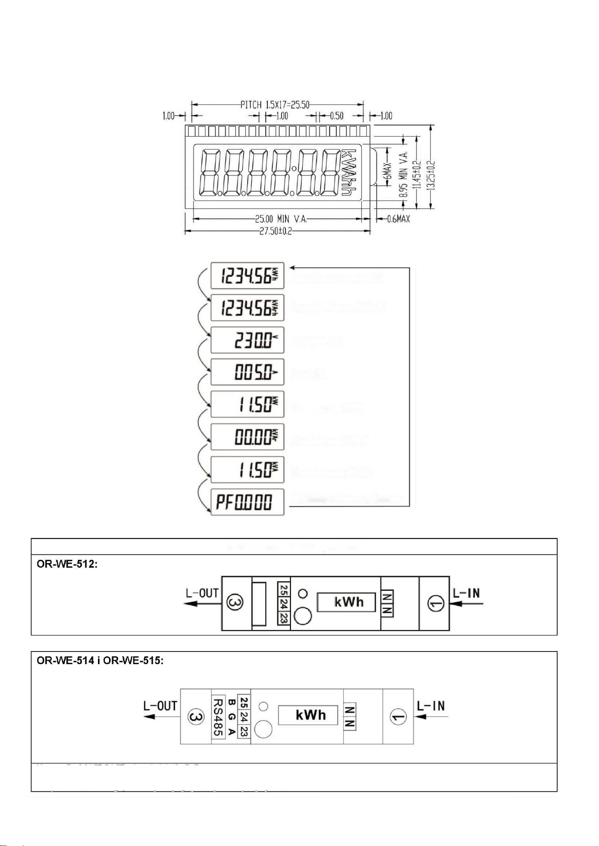
Backlit LCD.
Scroll of the display of current (A), voltage (V), etc.
Accurate measurement of active and wattless power.
2 modes of data display:
a. Automatic scroll mode: time interval is 5 s.
b. Button mode - using the external button to check data.
*Base current - specifies the current value when percentage measurement error is near zero. If the current flowing through the meter is greater than the base
current, then the measurement error has the minus sign. If the current flowing through the meter is lower than the base current, then the percentage
measurement error has the plus sign (percentage measurement error versus current).
The meter measures the electric energy properly within the whole measuring range, with an accuracy of the meter class.
Maximum current - the permissible maximum current to load the electric energy meter constantly.
Minimum current - the lowest value of the load current that is detected and registered by the meter.