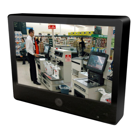
Vista VK2-PVM32CAM User manual

VK2-PVM27/32CAM User Manual V1.0
VK2-PVM27/32CAM
USER MANUAL

VK2-PVM27/32CAM User Manual V1.0

3

4
Before You Begin
Read these instructions before installing or operating this product.
Note: This installation should be made by a qualified service person and should conform to local codes.
This manual provides installation and operation information. To use this document, you must have the
following minimum qualifications:
A basic knowledge of CCTV systems and components
A basic knowledge of electrical wiring and low-voltage electrical connections
Intended use
Only use this product for its designated purpose; refer to the product specification and user documentation.
Customer Support
For assistance in installing, operating, maintaining and troubleshooting this product refer to this document and
any other documentation provided. If you still have questions, please contact Norbain Technical Support and
Sales:
Norbain SD, 210 Wharfedale Road, IQ Winnersh, Wokingham, Berkshire RG41 5TP, England.
UK +44 (0) 118 912 5000
Note: You should be at the equipment and ready with details before calling Technical Support.
Conventions Used in this Manual
Boldface or button icons highlight command entries. The following WARNING, CAUTION and Note
statements identify potential hazards that can occur if the equipment is not handled properly:
* WARNING:
Improper use of this equipment can cause severe bodily injury or equipment damage.
** Caution:
Improper use of this equipment can cause equipment damage.
Note: Notes contain important information about a product or procedure.
This apparatus is manufactured to comply with the radio interference.
A Declaration of Conformity in accordance with the following EU standards has been made. The
manufacturer declares that the product supplied with this document is compliant the provisions of
the EMC Directive 2004/108/EC, the CE Marking Directive 93/68 EEC and all associated
amendments.
All lead-free products offered by the company comply with the requirements of the European
law on the Restriction of Hazardous Substances (RoHS) directive: 2011/65/EU, which means
our manufacture processes and products are strictly “lead-free” and without the hazardous
substances cited in the directive.
The crossed-out wheeled bin mark symbolizes that within the European Union the product must
be collected separately at the product end-of-life. This applies to your product and any
peripherals marked with this symbol. Do not dispose of these products as unsorted municipal
waste.
* This symbol indicates electrical warnings and cautions.
** This symbol indicates general warnings and cautions.
NORBAIN SD reserves the right to make changes to the product and specification of the product from time to
time without prior notice.
WARNINGS AND CAUTIONS:
To reduce the risk of fire or electric shock, do not insert any metallic objects through the ventilation grills or other
openings on the equipment.


5
IMPORTANT SAFEGUARDS
1. Read these instructions.
2. Keep these instructions.
3. Heed all warnings.
4. Follow all instructions.
5. Do not use this apparatus near water.
6. Clean only with dry cloth.
7. Do not block any ventilation openings. Install in accordance with the manufacturer's
instructions.
8. Do not install near any heat sources such as radiators, heat registers, stoves, or other
apparatus (including amplifiers) that product heat.
9. Do not defeat the safety purpose of the polarized or grounding-type plug. A polarized plug has
two blades with one wider than the other. A grounding type plug has two blades and a third
grounding prong. The wide blade or the third prong is provided for your safety. If the provided
plug does not fit into your outlet, consult an electrician for replacement of the obsolete outlet.
10. Protect the power cord from being walked on or pinched particularly at plugs, convenience
receptacles, and the point where they exit from the apparatus.
11. Only use attachments/accessories specified by the manufacturer.
12. Unplug this apparatus during lightning storms or when unused for long periods of time.
13. Refer all servicing to qualified service personnel. Servicing is required when the apparatus
has been damaged in any way, such as power-supply cord or plug is damaged, liquid has
been spilled or objects have fallen into the apparatus, the apparatus has been exposed to
rain or moisture, does not operate normally, or has been dropped.
14. CAUTION - THESE SERVICING INSTRUCTIONS ARE FOR USE BY QUALIFIED SERVICE
PERSONNEL ONLY. TO REDUCE THE RISK OF ELECTRIC SHOCK DO NOT PERFORM
ANY SERVICING OTHER THAN THAT CONTAINED IN THE OPERATING INSTRUCTIONS
UNLESS YOU ARE QUALIFIED TO DO SO.
15. IEC60950-1/UL60950-1 or Certified/Listed Class 2 power source only.

6
Contents
Before You Begin 4
Intended use 4
Customer Support 4
WARNINGS AND CAUTIONS: 4
1Introduction 7
1.1 Components 7
1.2 Key Features 8
2Installation 9
2.1 Connections 9
Mechanical Installation 10
2.2 Resetting to the factory default settings 12
2.3 Network Connection & IP assignment 13
3Operation 14
3.1 Access from a browser 14
3.2 Access from the internet 15
3.3 Setting the admin password over a secure connection 15
3.4 Live View Page 16
3.5 Playback 18
3.6 Network Camera Setup 20
3.6.1 Basic Configuration 20
3.6.2 Video & Image 25
3.6.3 Audio 33
3.6.4 Event 34
3.6.5 System 54
3.6.5.1 PVM ( Logo upload) 70
6.9 Help 74
AAppendix 76
A.1 Troubleshooting 76
A.2 Alarm Connection 77
A.3 Preventive Maintenance 77
A.4 System Requirement for Web Browser 78
A.5 General Performance Considerations 78

7
1 Introduction
The VK2-PVM27/32CAM monitor has been designed specifically with self-scan till installation
applications in mind.
The monitor displays a logo until the in-built camera detects motion within it’s field of view, at which
point the logo is switched to the image form the camera.
An optional message can also be displayed over the top of the video image.
1.1
Components
This system comes with the followingcomponents:
VK2-PVM27/32CAM monitor
1
User Manual 1
Quick install guide 1
IR Remote control 1

8
1.2
Key Features
•
Brilliant video quality
The network camera offers the highly efficient H.265 or H.264 video compression, which
drastically reduces bandwidth and storage requirements without compromising image quality.
Motion JPEG is also supported for increased flexibility.
•
Quad streams
The network camera can deliver four video streams simultaneously using H.264, H.265 and
Motion JPEG.
This means that several video streams can be configured with different
compression
formats, resolutions and frame rates for different needs.
•
Intelligent video capabilities
The network camera includes intelligent capabilities such as enhanced video motion
detection. The network cameras external inputs and outputs can be connected to devices
such as sensors and relays, enabling the system to react to alarms and activate
lights or
open/closedoors.
•
Improved security
The network camera logs all user access, and lists currently connected users. Also, its full
frame rate video can be provided overHTTPS.
•
PoE+ (Power over Ethernet)
This network camera can be powered through PoE+(IEEE802.3AT), which simplifies
installation since only one cable isneededforcarrying power, as well as video controls.
•
ONVIF certificate
This is a global interface standard that makes it easier for end users, integrators, consultants,
and manufacturers to take advantage of the possibilities offered by network
video technology.
ONVIF enables interoperability between different vendor products,
increased flexibility,
reduced cost, and future-proofsystems.
•
Micro-SD recording support
The network camera also supports a micro-SD memory slot for local recording with removable
storage of type SDHC and SDXC.
•
Audio support
The Network Camera also supports two-wayaudio.

9
2 Installation
For the operation of the network camera, it is necessary to connect a network cable for
data
transmission, power connection from a PoE+ source, alternatively a separate 24VDc power supply
can be used to power the monitor. In addition to power an external alarm cable can be connected,
or a Micro SD card can be inserted to give a local recording function.
2.1
Connections
1)
A. Connecting the Power
Connect the power of 24 VDC for the PVM for the DC power.
–
Be careful not to reverse the polarity when connecting the power cable.
–
A router featuring PoE+ (Power over Ethernet) can also be used to supply power to
the
camera.
–
For the power specifications, refer to the appendix, product specification.
If PoE+ and 24 VDC are both applied, the camera will be supplied with power from
PoE+.
2)
B. PoE+ (Ethernet)
Connect a standard RJ-45 cable to the network port of the network camera. Generally a cross-
over cable is used for directly connection to PC, while a direct cable is used for connection to a
hub. You can also use a router featuring PoE+(IEEE802.3AT) (Power over Ethernet) to supply
power to the camera
3)
C. Connecting Audio
Connect external Mic to audio input line.
4)
D. Alarms
AI(Alarm In): You can use external devices to signal the network camera to react on
G(Ground): Connect the ground side of the alarm input and/or alarm output to the G (Ground)
connector.
AO(Alarm Out): The network camera can activate external devices such as buzzers or lights.
Connect the device to the AO (Alarm Out) and G (Ground) connectors.
5)
E. Micro SD memory slot on the BottomBoard
Remove the cap at bottom of the camera to insert the SD memory card.
6)
F. USB: For Monitor FW Update
7)
G. HDMI: HDMI signal input
8)
H. VGA:D-sub 15pin input

10
2.2
Mechanical Installation
1) Remove the access cover:
2) Connect ethernet cable to RJ45 port: PoE+ (IEEE802.3at) 30W required.
3) Replace access cover:
4) Mount the PVM27CAM/PVM32CAM to bracketry suitable for the application using either the
VESA100 x 100 or VESA200 x 100 on the rear

11
2.3
OSD ACCESS / IR REMOTE
Use either the buttons on the side of the PVM27CAM/PVM32CAM to enter the set up menus for the
monitor screen

12
Use the MENU key on the IR Remote to access the Camera function menus.
Power key: Monitor power on/off
Mute key: Mute the Audio
Key: Up/Down/Left/Right scrolling the cursor to desired function.
OK key: Confirmation key during the OSD operation.
Menu Key: Camera OSD control.
Exit Key: Exit the OSD menu.
: Monitor OSD control.
Source : Select VGA/HDMI/CAMERA
Info :Information
NOTE: For instructions on loading logos into the monitor see page 70 section
3.6.5.1 PVM Logo Upload
2.4
Resetting to the factory default settings
To reset the monitor to the original factory settings, in the monitor web page, go to the Setup >
System >
Maintenance web page (described in “System > Maintenance” of User Manual) or use
the remote control "Menu > Restore Defaults > All”change to YES and then click OK button.
CAUTION: When performing a Factory Reset, you will lose any settings that have been
saved. (Default IP192.168.30.220)

13
2.5
Network Connection & IP assignment
When a monitor is first connected
to the network, it is necessary to allocate an IP address to the
device with the “SmartManager” utility on the CD. (Default IP192.168.30.220)
1)
Connect the network camera/device to the network and power up.
2)
Start SmartManager utility (Start > All programs > SmartManager > SmartManager).
The main
window will display, and after a short while any network devices connected to the
network will be
displayed in thelist.
3)
Select the camera on the list and click right button of the mouse. You can see the pop-up
menu
as below.
4)
Select Assign IP Address. The Assign IP window will display. Enter the required IP address.
NOTE: For more
information, refer
to the
SmartManager
UserManual.

14
3 Operation
The monitor can be used with Windows operating system and browsers. The recommended
browsers are Internet Explorer, Safari, Firefox, Opera and Google Chrome with
Windows.
NOTE: To view streaming video in Microsoft Internet Explorer, set your browser to allow
ActiveXcontrols.
3.1
Access from a browser
•
Start a browser (Internet Explorer).
•
Enter the IP address or host name of the network camera in the Location/Address field
of your
browser.
•
Youcan see a starting page. Click Live View, Playback, or Setup to enter web page.
•
The network cameras Live View page appears in yourbrowser.

15
3.2
Access from the internet
Once connected, the network camera is accessible on your local network (LAN). To access
the
network camera from the Internet you must configure your broadband router to allow
incoming
data traffic to the network camera. To do this, enable the NAT traversal feature,
which will attempt
to automatically configure the router to allow access to the network cam-
era. This is enabled from
Setup > System > Network > NAT.For more information, please
see “System > Network > NAT”
of User Manual.
3.3
Setting the admin password over a secure connection
Togain access to the product, the password for the default administrator user must be set.
This is
done in the “Admin Password” dialog, which is displayed when the network camera
is accessed for
the setup at the first time. Enter your admin name and password, set bythe
administrator.
NOTE: The default administrator user name and password is “admin”. If the password is
lost, the
network camera must be reset to the factory default settings. Please see “Resetting
to the factory
defaultsettings.”
To prevent network eavesdropping when setting the admin password, this can be done via
an
encrypted HTTPS connection, which requires an HTTPS certificate (see NOTEbelow).
Tosetthe
passwordviaa standardHTTPconnection, enteritdirectlyinthefirstdialogshown
below. Toset the
password via an encrypted HTTPS connection, please see “System
> Security > HTTPS” of User Manual.
NOTE: HTTPS (Hypertext Transfer Protocol over SSL) is a protocol used to encrypt the
traffic
between web browsers and servers. The HTTPS certificate controls the encrypted
exchange of
information.

16
3.4
Live View Page
The Live View page comes in several screen modes. Users are allowed to select the most
suitable one out of those modes. Adjust the mode in accordance with your
PC specifications and
monitoring purposes.
1)
General controls
Live ViewPage PlaybackPage Setup Page Help Page
The video drop-down list allows you to select a customized or pre-
programmed video stream on the Live View page. Stream profiles are con-
figured under Setup > Basic Configuration > Video & Image. For more in-
formation, pleasesee “Basic Configuration> Video&Image” of User
Manual.
The resolution drop-down list allows you to select the most suitable one out
of
video resolutions to be displayed on Live View page.
The protocol drop-down list allows you to select which combination of pro-
tocols and methods to use depending on your viewing requirements, and
on
the properties of your network.
2)
Control toolbar
The live viewer toolbar is available in the web browser page only. It displays the following
buttons:
The Stop button stops the video stream being played. Pressing the key again toggles
the
start and stop. The Start button connects to the network camera or starts playing
a video
stream.
The Pause button pauses the video stream being played.
The Snapshot button takes a snapshot of the current image. The location where the
image is
saved can be specified.

17
The Digital Zoom button activates a zoom-in or zoom-out function for video image on
the live
screen.
The Full Screen button causes the video image to fill the entire screen area. No other
windows will be visible. Press the ‘Esc’ button on the computer keyboard to cancel full
screen
view.
The Manual Trigger button activates a pop-up window to manually start or stop the
event.
The Relay Output button manually triggers relay out. (This Icon appears only if “En-
able
alarm out” is selected in “Event Out - AlarmOut”.)
The Speaker button activates/deactivates externalspeaker.
The Mic button activates/deactivates microphoneinput.
Use this scale to control the volume of the speakers and microphones.
3)
Video Streams
The network camera provides several images and video stream formats. Your requirements and
the properties of your network will determine the type youuse.
The Live View page in the network camera provides access to H.264, H.265 and Motion JPEG
video streams, and to the list of available video streams. Other applications and clients
can
also access these video streams/images directly, without going via the Live View
page.

18
3.5
Playback
The Playback window contains a list of recordings made to the memory card. It shows each
recording’s start time, length, the event type used to start the recording, calendar and time
slice bar
indicates if the recording is existed ornot.
The description of playback window follows.
1)
Video Screen
Youcan see the video screen when playing the video clip in the Micro SDmemory.
2)
Playback Buttons
To view a recording data in the SD local storage, select it from the list and click the
Playbackbuttons.
Go to the first: go to the beginning of the videoclip.
Fast backward play: fast play backward of the video clip.
Backward play: play backward of the videoclip.
Step backward play: go back one frame of the video clip.
Pause: pause playback of the videoclip.
Step forward play: go forward one frame of the video clip.
Forward Play: play forward the videoclip.
Fast forward play: play fast forward of the video clip. Go
to the last: go to the end of the videoclip.
Clip copy: copy the video clip.
Zoom In: zoom in the videoclip.
Full Screen: display full screen of thevideo.

19
3)
Time Chart
Display an hour-based search screen for the chosen date. If there is recording data, a
blue
section will be displayed on a 24-hour basis. If you select a particular hour in the
chart, a
yellow square on the hour will bedisplayed.
4)
Speaker Control Bar
Use this scale to control the volume of thespeakers.
5)
Search Calendar
Search results from the SD local storage in the network camera connected are displayed
monthly. If there is a recorded data for a particular date, a blue square on the date will be
displayed. If you select a particular date in the calendar, a yellow square on the date will
be
displayed.
6)
Play Time
Displays time of the videoplaying.
7)
Event SearchWindow
Select a search option in the drop-down list and click GO button. You can also enter
the
time period for searching. If you click Start Date or End Date zone, displays Search
Calendar.
8)
Event List Window
Event List displays the event(s) that were recorded in the SD local storage. Select a list
and
click the play button. The video clip will beplayed.

20
3.6
Network Camera Setup
This section describes how to configure the networkcamera.
Administrator has unrestricted access to all the Setup tools, whereas Operators have access
to the
settings of Basic Configuration, which are Live View, Video & Image, Audio, Event,
Dome
Configuration, andSystem.
You can configure the network camera by clicking Setup either in the first connection page
or the
top second-right button of the Live View page. Accessing the network camera from a
computer for
the first time opens the Admin Password dialog box. Enter your administrator
or operator id and
password to get into setuppage.
NOTE: If the password is lost, the network camera must be reset to the factory default
settings. Please see “Resetting to the Factory Default Setting”.
3.6.1 Basic Configuration
Youcan see the device information in this informationpage.
This manual suits for next models
2
Table of contents
Other Vista Monitor manuals

Vista
Vista VFS100LEDe Series User manual

Vista
Vista VFS-300LED Guide

Vista
Vista TV14 Operation instructions

Vista
Vista TV14E Operation instructions

Vista
Vista VFS-300 Series Guide

Vista
Vista VM215 User manual

Vista
Vista VFS-200/HI-LITE Series User manual

Vista
Vista VLFSM15D_h User manual

Vista
Vista PVM27CAM User manual

Vista
Vista PVM10CAMN User manual

Vista
Vista PVM27DEC User manual

Vista
Vista VFS-221WHDA User manual

Vista
Vista VFSM15 User manual

Vista
Vista VFS132WHDA Guide

Vista
Vista VK2-PVM27CAM User manual

Vista
Vista VFS-200LED Guide

Vista
Vista DIAMOND User manual

Vista
Vista PVM18DEC User manual

Vista
Vista PVM19CAM User manual

Vista
Vista VK2-PVMxxDEC Series User manual