VISTEK V1623 Owner's manual

01/03/2005 V1623_2OM.DOC Page 1 of 15
V1623
V1623K
Video Analogue to Digital Converter
Module
Key Channel Analogue to Digital
Converter Module
INSTALLATION and OPERATION
© Vistek Electronics Ltd
Filename: V1623om.doc
Issue : 2
Date: June 2002
VISTEK Electronics Ltd
Wessex Rd
Bourne End
Buckinghamshire, SL8 5DT
ENGLAND
Tel. +44 1628 531221
Fax. +44 1628 530980
Web: www.vistek.tv

01/03/2005 V1623_2OM.DOC Page 2 of 15
01/03/2005 V1623_2OM.DOC Page 3 of 15
Video Analogue to Digital Converter Module
INSTALLATION AND OPERATION
1. DESCRIPTION
This manual covers both the V1623 video analogue to digital converter and the V1623K Key Channel
analogue to digital converter. The Key Channel module has reduced functionality from the other version,
as unnecessary controls and components have been removed. The V1623K uses the Y/G channel of
the unit for the Key signal and the Pb/B and Pr/R channels are fixed at black in the processing.
The V1623 is a video analogue to digital converter, which forms part of the Vistek V1600 range of
interface products. It is a 3U high card, which is fitted into either a V1601, V1603 or V1606 rack from
which it gets its power and control. A passive rear module, 16VR1H or 16VR3H, is required for all
signal interconnections.
The unit is fully dual standard for both 625/50 and 525/60 D1 signals. It can automatically detect the
input standard and operate accordingly, or it can also be forced into a standard regardless of the input.
The unit can handle the analogue component signals in various formats to produce the standard D1
digital output. The formats are: -
Y, Pb, Pr (standard levels, Beta levels or US MII levels), with or without set-up
GBR with or without set-up
The sync reference may be a separate signal 300mV – 4V, or extracted from the Y or G signals.
Levels and timing parameters can be adjusted, along with blanking controls. An internal test pattern
generator is also included for alignment purposes.
Video Gain + 6dB
Chroma Gain + 6dB
Black Level + 100mV
Green Gain + 6dB (GBR Mode only)
Blue Gain + 6dB (GBR Mode only)
Red Gain + 6dB (GBR Mode only)
Input Format Y/Pb/Pr, GBR, MII, Beta
Output Standard 525, 625
Reference select Y/G, External
Reference Fail Mode Free Run, Black, Mute
Test Pattern Bars, Black, Picture Edge, Ramp, Split screen
Monochrome mode Colour, Monochrome
Picture position + 2.3 us
Y/C Timing + 0.55 us
Output Delay 0 – ½ line
Vertical Blanking
Wide Screen Blanking 4:3, 14:9, 16:9, Key Level
Error Detection & Handling On, Off
Limiting Set-up ear removal (525 modes only)
Engineering Mode Enables extra test Patterns & Mono Modes
Alignment mode Module alignment set-up modes
In common with all Vistek V1600 modular units there is a local control panel, which lets the user adjust
most of the controls. In addition the module may be controlled remotely using the DART system. DART
is the general purpose control architecture supplied by Vistek and other manufacturers, and enables full
control and monitoring of this and all other V1600 units.

01/03/2005 V1623_2OM.DOC Page 4 of 15

01/03/2005 V1623_2OM.DOC Page 5 of 15
2. INSTALLATION
2.1 REAR PANEL CONNECTIONS
The V1623 rear module connections are shown below.
3U Rear Module (16VR3H)1U Rear Module (16VR1H)
O/P
A2
O/P
A3
O/P
A4
Sync
(loop)
I/P
Y/G
I/P
Pb/B
I/P
Sync
I/P
Pr/R
DART
O/P
A1
O/P
A1
O/P
A2
O/P
A3
O/P
A4
I/P
Y/G
I/P
Pb/B
I/P
Pr/R
I/P
Sync
Sync
(loop)
* The V1623K Module has the Y/G input labeled as Key and the Pb/B and
Pr/R inputs are not connected.
2.2 INTERFACING
SIGNAL COMMENTS
Power 7.5W Supplied from rack
Analogue
Inputs BNC Video ( 700mV nominal, but will handle 1.4V signals)
Sync Reference (300mV – 4V) (looping un-terminated)
SDI O/P 1,2,3,4 BNC Video to SMPTE 259M. Drive cable length up to 200m
2.3 INSERTION DELAY
Sync Reference to SDI Output 6.3µs
01/03/2005 V1623_2OM.DOC Page 6 of 15
2.4 HARDWARE
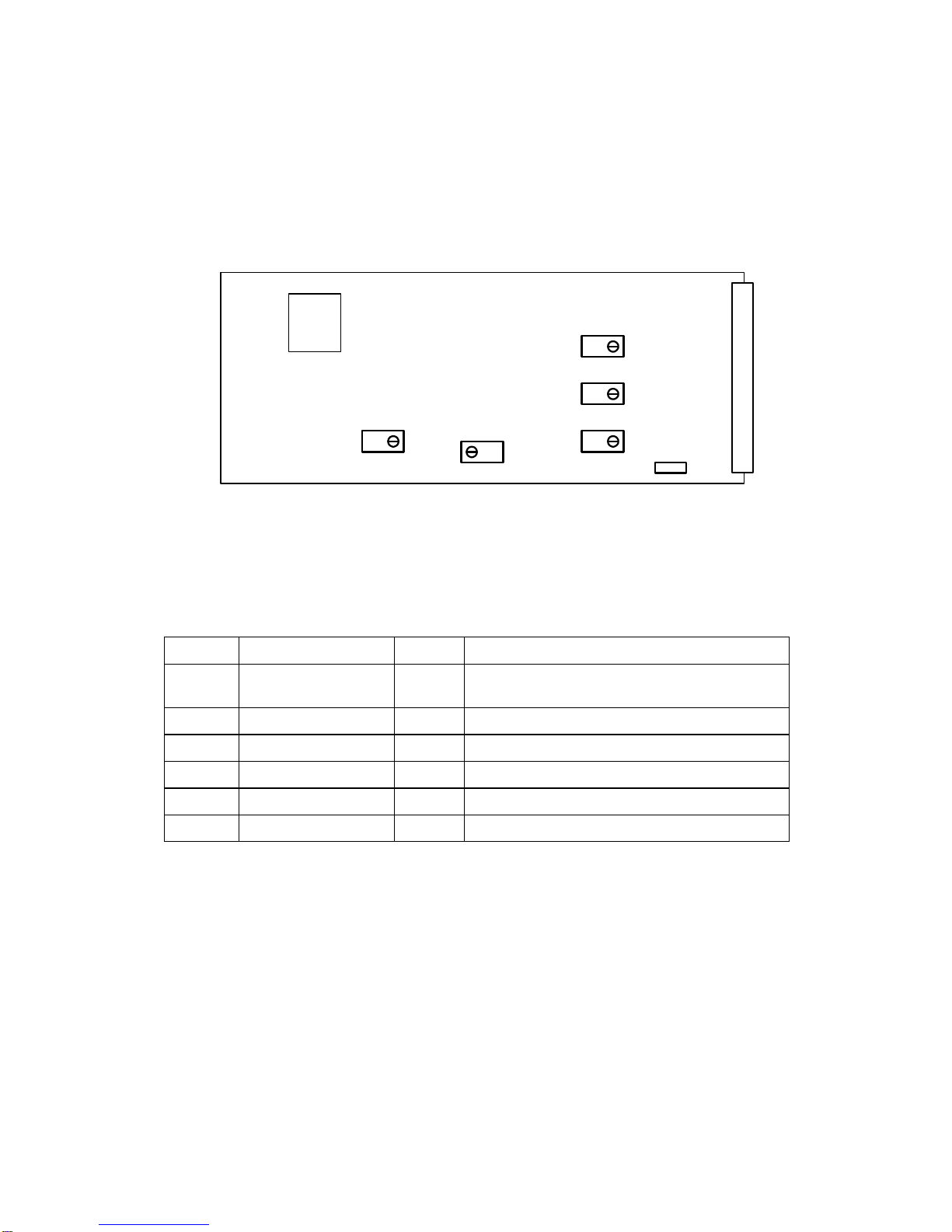
The figure below shows diagrammatically the printed circuit board along with certain other components
of interest. In particular it shows the position and orientation of the controls and switches, which set up
the calibrated levels and External Reference level range.
The EPROM location is shown, as it is the component that would need to be changed as a result of any
software upgrade in the field.
Front Panel
Rear Connector
EPROM
SW5
VR1
VR2
VR3VR4 VR5
The purposes of the controls and switches are shown in the following table. Details of their operation
are described in later sections.
ITEM Title Section Comments
SW5 External Reference
input range Sets the reference input voltage range between
300mV - 1V and 1V - 4V
VR1 Y/G amplitude Calibrates the input analogue circuit
VR2 Pb/B amplitude Calibrates the input analogue circuit
VR3 Pr/R amplitude Calibrates the input analogue circuit
VR4 27MHz frequency Sets the freerun frequency of the oscillator
VR5 Fine phase Sets the clock edge to reference timing

01/03/2005 V1623_2OM.DOC Page 7 of 15
2.5 FRONT PANEL
REM +V
Local
Rem
V1623
Video
ADC
+-
DART Control Access and Power indicators
Local Control Page Selected
Local Control Parameter Selected
UP Button
Mode and Value LEDs (see below)
DOWN Button
REMOTE / LOCAL control selection
525 625 SDI Format Indicator
Ref
Local Control Selection
Select
V Gain A
C Gain B
G Gain C
B Gain D
R Gain E
Black F
321
The front panel shown above has three purposes:
Provide the user with the operating conditions
Offer Local control and indication of the primary controls
Select the control source
2.5.1 Operating Conditions
The LEDs at the top of the panel have these meanings
REM Short blinks to indicate access by the DART controller, if fitted. It does not
indicate that the unit is in one of its remote control modes.
+V Indicates that 5V is present on the board. This is derived from the +15V
distributed through the rack.
525 Indicates that a 525/60 format signal is being Output.
Green = Input. Amber = Test Pattern
625 Indicates that a 625/50 format signal is being Output.
Green = Input. Amber = Test Pattern
Ref Indicates that a valid Reference signal is being received.
Green = Locked Amber = Standard conflict Red = Failed

01/03/2005 V1623_2OM.DOC Page 8 of 15
2.5.2 Adjustments
The central section is used in Local control to select which of the four available pages and which of upto
6 available menus is to be adjusted and to make the adjustment. In remote mode or Page 0, menu 0,
the menu LEDs indicate by flashing if any of the gains are off their calibrated settings.
Selecting a page is done by holding down the select button and pressing the τbutton. The pages will
rotate around 0 – 1 – 2 – 3 – 4 – 0 etc.
Selecting a menu is done by pressing and releasing the select button. The menus will rotate A – B – C –
D – E – F – null – A etc. (Not all menus are available on each page, so non-available menus will be
skipped. Availability can also depend on operating modes.)
Once a control has been selected then it is changed by pressing the σand τbuttons.
Level and timing adjustments have rate laws on the σand τbuttons, so holding them down will increase
the speed of adjustment. Parameter adjustments are done in single steps, requiring button press and
release to step between them.
Any adjustment can be returned to its calibrated value by pressing the σand τbuttons simultaneously
for at least five seconds.
The three central LEDs give an indication of the parameter status. The exact meaning of each LED is
described in the following table. These LEDs will flash Amber on Page 0, menu 0 if the unit is left in
Engineering mode or Red if it is in Alignment mode.
V 1623 Menu’s.
Page Menu Item Parameter /
Value ‘-‘ led ‘ ‘ led ‘+’ led
0 A Video Gain Calibrated Off Green Off
+ve gain Off Off Yellow
-ve gain Yellow Off Off
0 B Chroma Gain Calibrated Off Green Off
+ve gain Off Off Yellow
-ve gain Yellow Off Off
0 C *Green Gain Calibrated Off Green Off
(RGB Mode +ve gain Off Off Yellow
only) -ve gain Yellow Off Off
0 D *Blue Gain Calibrated Off Green Off
(RGB Mode +ve gain Off Off Yellow
only) -ve gain Yellow Off Off
0 E *Red Gain Calibrated Off Green Off
(RGB Mode +ve gain Off Off Yellow
only) -ve gain Yellow Off Off
0 F Black Level Calibrated Off Green Off
+ve gain Off Off Yellow

01/03/2005 V1623_2OM.DOC Page 9 of 15
-ve gain Yellow Off Off

01/03/2005 V1623_2OM.DOC Page 10 of 15
Page Menu Item Parameter /
Value ‘-‘ led ‘ ‘ led ‘+’ led
1 A I/P Standard YUV Off Off Off
RGB Off Off Green
RGB + Set-up Yellow Off Green
MII + Set-up Yellow Green Off
Beta + Set-up Yellow Green Green
Beta Off Green Green
1 B O/P Standard Last Used Off Off Off
Default 525 Green Off Off
Default 625 Off Green Off
Forced 525 Yellow Off Off
Forced 625 Off Yellow Off
1 C Reference I/P External Off Off Off
Y/G Off Off Green
1 D Ref Fail Free run Off Green Off
Mode O/P Black Off Yellow Off
O/P Mute Off Red Off
1 E Test Patterns Off Off Off Off
Colour Bars Off Off Yellow
Split Bars Yellow Off Yellow
Black Off Yellow Off
1 F Mono Mode Colour Green Green Green
Mono Green Off Off
2 A Picture Calibrated Off Green Off
Position Sync’s late Off Off Yellow
(wrt picture) Sync’s early Yellow Off Off
2 B *Y/C Timing Calibrated Off Green Off
(YUV Mode Chroma late Off Off Yellow
Only) Chroma early Yellow Off Off
2 C O/P Delay Minimum Off Green Off
Delay Off Off Off
2 D Vertical Normal Off Green Off
Blanking Narrow Yellow Off Off
2 E Widescreen Off Off Off Off
Blanking 14:9 Off Off Green
16:9 Off Green Off
14:9 + Key Yellow Off Green
16:9 + Key Yellow Green Off
01/03/2005 V1623_2OM.DOC Page 11 of 15
Page Menu Item Parameter /
Value ‘-‘ led ‘ ‘ led ‘+’ led
2 F EDH On Off Green Off
Off Off Off Off
3 A Limiting Off Off Off Off
Set-up ear limit Off Yellow Off
3 B Operating Normal Off Off Off
Mode Engineering Yellow Yellow Yellow
Alignment Red Red Red
3 C Test Off Off Off Off
Patterns Colour Bars Off Off Yellow
Split Bars Yellow Off Yellow
Black Off Yellow Off
(* Eng. Mode Edge of picture Off Off Red
Only) Split Edge Yellow Off Red
SDI Ramp Off Red Off
Split Ramp Yellow Red Off
3 D Mono Modes Colour Green Green Green
Y Only Green Off Off
(* Eng. Mode U Only Off Green Off
Only) V Only Off Off Green
**1 **A **Alignment Y to Y O/P only Off Off Off
B to Y O/P only Off Off Green
R to Y O/P only Yellow Off Green
Y/Pb to Y/Pb O/P Yellow Green Off
Y/Pr to Y/Pr O/P Off Green Off
Normal Off Green Green
V1623K Menu’s.
Page Menu Item Parameter /
Value ‘-‘ led ‘ ‘ led ‘+’ led
0 A Video Gain Calibrated Off Green Off
+ve gain Off Off Yellow
-ve gain Yellow Off Off
0 F Black Level Calibrated Off Green Off
+ve gain Off Off Yellow
-ve gain Yellow Off Off

01/03/2005 V1623_2OM.DOC Page 12 of 15
Page Menu Item Parameter /
Value ‘-‘ led ‘ ‘ led ‘+’ led
1 B O/P Standard Last Used Off Off Off
Default 525 Green Off Off
Default 625 Off Green Off
Forced 525 Yellow Off Off
Forced 625 Off Yellow Off
1 C Reference I/P External Off Off Off
Y Off Off Green
1 D Ref Fail Free run Off Green Off
Mode O/P Black Off Yellow Off
O/P Mute Off Red Off
1 E Test Patterns Off Off Off Off
Staircase Off Off Yellow
Split Staircase Yellow Off Yellow
Black Off Yellow Off
2 A Picture Calibrated Off Green Off
Position Sync’s late Off Off Yellow
(wrt picture) Sync’s early Yellow Off Off
2 C O/P Delay Minimum Off Green Off
Delay Off Off Off
2 D Vertical Normal Off Green Off
Blanking Narrow Yellow Off Off
2 E Widescreen Off Off Off Off
Blanking 14:9 Off Off Green
16:9 Off Green Off
14:9 + Key Yellow Off Green
16:9 + Key Yellow Green Off
2 F EDH On Off Green Off
Off Off Off Off

01/03/2005 V1623_2OM.DOC Page 13 of 15
Page Menu Item Parameter /
Value ‘-‘ led ‘ ‘ led ‘+’ led
3 A Limiting Off Off Off Off
Set-up ear limit Off Yellow Off
3 B Operating Normal Off Off Off
Mode Engineering Yellow Yellow Yellow
Alignment Red Red Red
3 C Test Off Off Off Off
Patterns Staircase Off Off Yellow
Split Staircase Yellow Off Yellow
Black Off Yellow Off
(* Eng. Mode Edge of picture Off Off Red
Only) Split Edge Yellow Off Red
SDI Ramp Off Red Off
Split Ramp Yellow Red Off
2.5.3 Control Source
The lowest switch has three positions and selects the control source:
Rem Control is from the DART system. This requires the use of an external
controller running a suitable programme, which communicates with multiple
racks using the Dartnet protocol.
Local Control is from the front panel itself.

01/03/2005 V1623_2OM.DOC Page 14 of 15
2.6 INITIALISATION
When the unit powers up it will be reset to the same conditions as when power was removed until it is
changed. In the Remote control mode any changes will be made by the control system, but in Local
they will be made on the front panel.
In Local mode the control panel will start up at page 0, menu 0. This is also the case when it is switched
into remote mode.
There are separate stores for adjustments and parameters on the module for Local and Remote modes,
so the unit may change its settings when switched between the control modes.
3. OPERATION
3.1 ADJUSTMENT RANGES
The adjustment ranges on the main parameters are:
PARAMETER RANGE
Video Gain ±6dB (aggregate)
Chroma Gain ±6dB (aggregate)
Green Gain ±6dB (aggregate)
Blue Gain ±6dB (aggregate)
Red Gain ±6dB (aggregate)
Black Level ±100 levels (~100mV)
Since the gain components are subject to both the video, chroma and individual colour gains the applied
gains are compounded. However the overall gain limit is still ±6dB.
Since the control system does the gain compounding, there is no loss of signal integrity. For example a
video gain of +3dB and a chroma gain of -3dB will have no effect on the chrominance components at all,
so there will be no limiting or loss of resolution.
3.2 FUNCTION ORDER
The Black Level offset is applied before the gain stages. This is considered the best arrangement when
the offset is used to correct for an incorrect input, such as may occur with poor quality input signals.
3.3 INPUT FORMAT
The input format may be selected to be either Y,Pb,Pr or GBR. In addition to these formats variations
can be selected to handle set-up on luminance and GBR signals, or amplitude variations encountered
from certain video tape formats.
3.4 OUTPUT STANDARD
The output standard of the unit can be controlled in several ways. The module can be left to decide
automatically what standard to use according to the input reference signal, or forced to always produce
a certain standard.
When the reference fails the unit can be set to default to the last used standard or default to a given
standard. The output can also be selected to freerun, output Black or mute if the reference fails.

01/03/2005 V1623_2OM.DOC Page 15 of 15
3.5 Y/C DELAY AND PICTURE POSITION
The Y/C delay control will allow adjustments to be made for timing errors between the component
signal. It is only operational in the Y,Pb,Pr modes.
The Picture position allows timing adjustments to be made to align the Reference input with the video
inputs.
3.6 VERTICAL AND WIDE SCREEN BLANKING
Vertical Blanking is nominally set to blank all the lines during the vertical interval. It can however be
adjusted to allow extra lines through, removing a line of blanking per field with each adjustment, upto the
standards maximum.
Standard Field 1 Field 2
625 Line 6 - 22 Line 318 - 335
525 Line 10 - 19 Line 273 - 282
Wide screen blanking can be added to reduce the picture height to a 14:9 or 16:9 aspect ratio. The
value of the blanking level can also be set to Key mode, which will put the luminance channel to a digital
value of 63 during the active picture blanking section and change any other occurrence of 63 in the
active picture luminance channel to 64.
3.7 TEST PATTERN GENERATOR
The internal test pattern generator produces Colour Bars and Black, which are legal signals for
transmission plus, when in Engineering mode, Edge + centre of picture markers and SDI Ramp. All the
test patterns, except Black can also be put into Split screen mode, so half the picture is test pattern and
the other half Input video.
3.8 EDH
The V1623 contains an EDH generator. This means a correct EDH data packet is always created on
the output, when it is switched on.
3.9 SETUP EAR REMOVAL
When a 525 video input is used with set-up, it is not possible to accurately know where the pedestal
starts and stops, due to the specification differences between analogue and digital horizontal blanking.
Therefore sometimes small positive or negative pulses are present on the SDI output following set-up
removal. The set-up ear removal option will detect and remove any negative going pulses within the
uncertainty period at the start and end of the lines.
3.10 ENGINEERING AND ALIGNMENT MODE
The Engineering mode allows additional Test patterns to be selected, which are not legal signals for
transmission, Edge + Centre Picture Markers and SDI Ramp. It also allows selection of individual
output channels to provide Y only, Pb only, Pr only or colour output. (These signals and modes are
inhibited when not in Engineering mode).
The Alignment mode is only available from the front control panel when the module is in Local mode. It
allows an Engineer to align the video paths through the unit a single channel at a time onto the Y
output.
This manual suits for next models
1
Table of contents
Other VISTEK Media Converter manuals


Popular Media Converter manuals by other brands


H&B
H&B TX-100 Installation and instruction manual

Bolin Technology
Bolin Technology D Series user manual

IFM Electronic
IFM Electronic Efector 400 RN30 Series Device manual

GRASS VALLEY
GRASS VALLEY KUDOSPRO ULC2000 user manual

Linear Technology
Linear Technology DC1523A Demo Manual

Lika
Lika ROTAPULS I28 Series quick start guide

Weidmuller
Weidmuller IE-MC-VL Series Hardware installation guide

Optical Systems Design
Optical Systems Design OSD2139 Series Operator's manual

Tema Telecomunicazioni
Tema Telecomunicazioni AD615/S product manual

KTI Networks
KTI Networks KGC-352 Series installation guide

Gira
Gira 0588 Series operating instructions

Lika
Lika SFA-5000-FD user guide